Note: Descriptions are shown in the official language in which they were submitted.
CA 02630281 2008-05-16
WO 2007/057629 PCT/GB2006/003744
- 1 -
Aircraft Fuel Pipe Coupling
The present invention relates to aircraft fuel pipe
couplings and in particular but not exclusively flexible pipe
couplings for connecting a double-walled pipe in an aircraft fuel
system to another fuel pipe.
In aircraft fuel systems it is often necessary to use
double-walled pipes, connectors and couplings in order to protect
from fuel leakage. When the risk of leakage is high, for example
in the pressurised fuselage of an aircraft, the entire fuel
system may be double-walled. Where the risk of leakage is less,
it may only be the couplings that are double-walled. Further
complications arise from the need to use flexible couplings in
order to compensate for manufacturing tolerances, structural
deflections or thermal effects.
Figure 1 of the attached drawings shows a prior art coupling
connecting a single-walled pipe (not shown, but positioned to the
left of the coupling as shown in Figure 1) and a double-walled
pipe 105 (to the right of the coupling as shown in Figure 1).
The coupling comprises (a) a rigid coupling part 101 and (b) a
flexible coupling part 108. The rigid coupling part 101 is
rigidly attached to a single-walled pipe by means of a connector
106. The flexible coupling part 108 comprises an inner flexible
coupling 103, an outer flexible coupling 104 joined to the
double-walled pipe 105 and an outer removable sleeve 102. The
double-walled pipe 105 and connector 106 are connected to each
other via the inner flexible coupling 103 and are allowed to
float relative to each other by means of two 0-ring seals 109 of
the inner flexible coupling 103. The outer flexible coupling 104
similarly comprises one 0-ring seal 110 allowing axial movement
between the outer flexible coupling 104 and the outer removable
sleeve 102. The movement provided by the seals 109, 110 of the
CA 02630281 2008-05-16
WO 2007/057629 PCT/GB2006/003744
- 2 -
inner and outer flexible couplings 103, 104 have different
centres of rotation. This can subject the coupling to side loads
that increase seal and coupling wear and can limit the angular
deflection allowable between the opposite ends of the coupling,
which may for example rotate relative to each other about axis
107. The positioning of the seals 109, 110 also makes the
coupling relatively bulky, thereby requiring a relatively large
volume in which to fit. The coupling includes a large number of
components that create complexity in the manufacturing process.
The prior art coupling also requires complex electrical bonding
arrangements between the pipes.
The present invention seeks to mitigate or overcome one or
more of the above-identified disadvantages associated with the
prior art coupling.
The invention provides a coupling for connecting fuel pipes
where at least one of the fuel pipes is double-walled, the
coupling comprising
a pipe-end fitting, the pipe end fitting including a male
outer surface and a female inner surface,
a double-walled socket arrangement, the double-walled socket
arrangement including a female outer socket and a male inner
shaft, the pipe-end fitting being at least partially accommodated
in the region between the female outer socket and the male inner
shaft,
a first seal ring providing a seal between the female inner
surface of the pipe end fitting and the male inner shaft of the
double-walled socket arrangement, and
a second seal ring providing a seal between the male outer
surface of the pipe-end fitting and the female outer socket of
the double-walled socket arrangement, wherein
CA 02630281 2008-05-16
WO 2007/057629 PCT/GB2006/003744
- 3 -
the coupling is so arranged that the pipe end fitting and
the double walled socket arrangement are able to pivot relative
to each other.
An embodiment of the invention described below
advantageously reduces the number of parts used in the coupling
as compared to the prior art coupling of Figure 1, thereby
reducing both the manufacturing cost and the risk of mal-
assembly. An embodiment of the invention described below enables
couplings to be produced that are shorter and more compact than
the prior art coupling as illustrated by Figure 1, reducing the
weight of the coupling and the volume occupied by the coupling.
The coupling of the embodiment furthermore provides improved
overall flexibility, in terms of increased ability to accommodate
angular deflections, of the coupling, and the side loads on the
seals may be reduced. Of course other embodiments of the
invention may provide such advantages and some embodiments may
only provide some of the advantages mentioned.
The centres of the first and second seal rings are
preferably not separated significantly from each other, but need
not be coincident. The first and second seal rings may be
arranged such that the angle between (a) a first notional line
extending from the centre of the second seal ring to a first
point on the surface of the second seal ring and (b) a second
notional line extending from the centre of the second seal ring
to a second point on the outer surface of the first seal ring,
the first and second points being chosen such that their
separation is minimised, is between 0 and 5 degrees, and more
preferably between 0 and 2 degrees.
The first and second seal rings may be arranged such that,
in the direction normal to the plane of the first seal, the
distance between the centres of the first and second seals is
between 0 and 10mm, and more preferably between 0 and 5mm.
CA 02630281 2008-05-16
WO 2007/057629 PCT/GB2006/003744
- 4 -
The first and second seal rings may be arranged to be
substantially coplanar. The centres of the first and second seal
rings may be coincident. The pipe end fitting and the double-
walled socket arrangement may be able to slide relative to each
other both towards and apart from each other. The arrangement of
the first seal ring may permit sliding movement of the female
inner surface of the pipe end fitting relative to the male inner
shaft of the double-walled socket arrangement. The arrangement of
the second seal ring may permit sliding movement of the male
outer surface of the pipe end fitting relative to the female
outer socket of the double-walled socket arrangement.
The pipe end fitting and the double-walled socket
arrangement may be able to pivot relative to each other by up to
at least +/- 2 degrees, or even up to as high as +/- 5 degrees.
The double-walled socket arrangement may be defined by a
first unitary part. The pipe end fitting may be defined by a
second unitary part. The coupling may thereby have fewer parts
in comparison to prior art couplings. In certain examples of the
present invention, the double-walled socket arrangement may
comprise three unitary parts, in the form of a first part that
defines the male inner shaft and second and third parts that
together define the female outer socket. Such a construction,
whilst comprising more parts than necessary, may aid assembly of
the coupling during manufacture and/or fitting.
An electrical connection strap may electrically connect the
double-walled socket arrangement and the pipe end fitting.
The coupling may include a seal groove in which one of the
first and second seal rings is accommodated. The seal groove may
have a Gamah profile. The seal groove and seal ring arrangement
may be in the form of a Gamah profile. The groove may have a
width greater than the diameter of the cross-section of the seal
ring. The groove may have a depth less than the diameter of the
CA 02630281 2008-05-16
WO 2007/057629 PCT/GB2006/003744
- 5 -
cross-section of the seal ring. The groove may have a wall
defining a surface against which in use the seal ring is urged,
the wall diverging outwardly, for example so that the seal ring
is urged to expand in diameter when urged against the wall.
The coupling may be provided independently of a pipe. At
least one of the double-walled socket arrangement and the pipe
end fitting may be connected to a fuel pipe.
The coupling may be connected to the fuel pipe by means of a
connection that includes a sleeve. Advantageously, the maximum
angle of pivoting between the double-walled socket arrangement
and the pipe end fitting depends on the position of the sleeve.
The fuel pipe may be a double-walled fuel pipe comprising an
inner pipe wall and an outer pipe wall. Where a sleeve is
provided, the sleeve may be connected to the outer pipe wall of
the double-walled fuel pipe. During.construction, the sleeve may
be withdrawn to allow room for the inner pipe wall to be welded
to the coupling. The sleeve may thereafter be moved to cover the
weld so formed. In that position the sleeve may be welded to
both the outer pipe wall and the coupling. The outer pipe wall
of the double-walled fuel pipe may be welded along its length.
In such a case, the provision of a sleeve for the purpose of
facilitating the joining of the coupling to a double-walled pipe
may be unnecessary.
Preferably at least part of the region between the female
outer socket and the male inner shaft of the double-walled socket
arrangement is in fluid communication with at least part of the
region between the inner pipe wall and the outer pipe wall of the
double-walled fuel pipe. The fluid communication between the
double-walled socket arrangement and the double-walled pipe may
be facilitated by at least one aperture, and preferably a
multiplicity of apertures, located between the first and second
seal rings. The fluid communication between the double-walled
CA 02630281 2008-05-16
WO 2007/057629 PCT/GB2006/003744
- 6 -
socket arrangement and the double-walled pipe may be facilitated
by a ring of holes located between the first and second seal
rings.
The coupling may be associated with a local drain port for
the drainage of fuel from a region between the female outer
socket and the male inner shaft of the double-walled socket
arrangement. For example, the coupling may be arranged to
connect to an adjacent fitting including such a drain port and
may for that purpose be provided with a drainage outlet arranged
to connect to a drainage inlet of a drain port of the adjacent
fitting. The drain port may therefore be included as a part of
the adjacent fitting. The coupling may include a local drain
port.
The coupling of the invention may be connected via a double-
walled pipe to another coupling of the invention according to any
aspect of the invention.
The present invention also provides a fuel system comprising
at least one coupling according to the invention as described
herein. The present invention further provides an aircraft
including such a fuel system.
The present invention yet further provides a kit of parts
for constructing a coupling according to the invention described
herein, the kit inclading
a double-walled socket arrangement and
a pipe end fitting. The double-walled socket arrangement
and/or the pipe end fitting may incorporate any of the features
of the coupling of the present invention mentioned herein. For
example, the kit may further include the first and second seal
rings.
Embodiments of the pipe end will now be described, by way of
example only, with reference to the accompany drawings of which:
CA 02630281 2008-05-16
WO 2007/057629 PCT/GB2006/003744
- 7 -
Figure 1 shows a coupling of the prior art,
Figure 2 and 2a show a cross-section of a double-walled pipe
coupling according to a first embodiment of the
invention,
Figure 3 shows an exploded view of a double-walled pipe
assembly of a second embodiment,
Figure 4 shows a cross-section of the double-walled pipe
assembly of the second embodiment,
Figure 5 shows a drain port as present in both the first
and second embodiments,
Figure 6 shows a cross-section of a stepped sleeve of a
coupling of a third embodiment,
Figure 7 shows a cross-section of a retained pipe
coupling of a fourth embodiment,
Figure 8 shows a cross-section of a double-walled
coupling of a fifth embodiment connecting
double-walled pipes,
Figure 9 shows a cross-section of a double-walled
coupling of a sixth embodiment connecting
single-walled pipes, and
Figure 10 shows a cross-section of part of a double-
walled pipe coupling according to a seventh
embodiment of the invention.
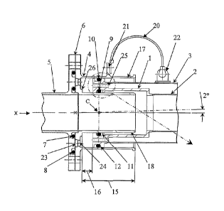
Figures 2 and 2a show a coupling according to a first
embodiment of the invention. The coupling is arranged about an
axis X and joins a single-walled rigid pipe 5 (on the left in
Figure 2) and a double-walled rigid pipe (on the right in Figure
2) comprising an inner rigid pipe wall 2 and an outer rigid pipe
wall 3. The coupling comprises a unitary end fitting 1 attached
by fusion welding to the double-walled pipe 2, 3. The coupling
also comprises a unitary double-walled socket 4 attached to the
CA 02630281 2008-05-16
WO 2007/057629 PCT/GB2006/003744
- 8 -
adjacent single-walled pipe 5 by means of a split flange, the
split flange comprising a flange on the single-walled pipe 5 and
a corresponding flange on the double-walled socket 4, the split
line indicated by the arrow 6. The single-walled pipe 5 in this
embodiment is in the form of a single-walled connector pipe
including an end flange, which is rigidly attached to the
aircraft structure (to the rear spar - not shown). The
connection of the double-walled socket 4 and the single-walled
pipe 5 is sealed by an inner static 0-ring seal 7 and an outer
static 0-ring seal 8. The double-walled socket has an inner wall
which defines a male inner shaft 18 and an outer wall which
defines a female outer socket 17. The end fitting 1 is partially
accommodated in the region between the male inner shaft 18 and
the female outer socket 17 of the double-walled socket 4. The
bolted split flange is separated by removing the bolts and
pushing the double-walled socket 4 axially along the end fitting
1.
The end fitting 1 includes a female inner seal groove 11
defining a part of a female inner surface and a male outer seal
groove 12 defining a part of a male outer surface. The end
fitting 1 slidingly engages with, and is attached to, the double-
walled socket 4 by means of an inner dynamic 0-ring seal 9
installed in the female inner seal groove 11 and an outer dynamic
0-ring seal 10 installed in the male outer seal groove 12. The
female outer socket 17 of the double-walled socket 4 forms the
sealing surface that engages with the outer dynamic 0-ring seal
10. Similarly, the male inner shaft 18 of the double-walled
socket 4 forms the sealing surface that engages with the inner
dynamic 0-ring seal 9.
The male outer seal groove 12 is based on a well known
profile, often referred to as a "Gamah" profile. Further details
concerning this sealing arrangement is provided in US 3,186,739.
CA 02630281 2008-05-16
WO 2007/057629 PCT/GB2006/003744
- 9 -
The female inner seal groove 11 is similar to the male outer seal
groove 12 but is mirrored and reoriented in relation to the male
outer seal groove 12 in order to maintain the correct position of
the inner dynamic 0-ring seal 9 in the female seal groove 11 when
the inner pipe 2 is pressurised and also to ensure the inner and
outer dynamic 0-ring seals 9, 10 are aligned in the same plane.
As shown in Figure 2a, due to the differences in pressure
direction (P) acting on the inner dynamic 0-ring seal 9 and the
outer dynamic 0-ring seal 10, the thick annular flange 37 on the
female inner seal groove 11 is positioned on the opposite side of
the seal groove when compared to the male outer seal groove 12.
It will be noted that the seal rings 9, 10 lie on the same plane
and are centred on the same point (a point on the axis X of the
coupling). The geometry of the thick annular flange 37, the thin
annular flange 38 and the bottom face 36 of the female inner seal
groove 11 is similar to the standard Gamah profile. In relation
to the female inner seal groove 11 and the male outer seal groove
12, each groove is defined by a thick flange and a thin flange.
The thick flange in each case defines an internal wall of the
groove that diverges outwardly with distance from the base of the
groove. For example, with reference to Figure 2a, the inner seal
ring 9, when exposed to fluid pressure P, is urged against the
thick flange 37 of the groove 11 and is therefore also urged, to
a limited extent, away from the base 36 of the groove and against
the sealing surface provided by the male inner shaft 18 opposite
the groove 11.
The coupling is capable of allowing up to two degrees
angular misalignment between pipe centrelines, with combined or
separate axial movement. The ability of the coupling to
accommodate such angular misalignment is provided by the
particular arrangement of the connection between the end fitting
1 and the double-walled socket 4 of the coupling. For example,
CA 02630281 2008-05-16
WO 2007/057629 PCT/GB2006/003744
- 10 -
the substantially coplanar arrangement of the seal rings 9, 10,
that provide the flexible sealed connection, allows flexing of
the coupling about a centre C of rotation that is position at the
single shared centre of the sealing rings 9, 10. It will of
course be appreciated that the end fitting 1 and the double-
walled socket 4 may pivot relative to each other about a centre
of rotation that is not in the plane of the seal rings 9, 10
and/or which is not on the axis X of the coupling. Of course,
the amount of angular displacement feasible between the end
fitting 1 and the double-walled socket 4 will reduce with an
increase in the distance of the centre of rotation from the
optimum centre of rotation (which is thought to be at the centre
C of the sealing rings 9, 10). It will also be understood from
the foregoing that the centre of pivoting between the end fitting
1 and the double-walled socket 4 need not be fixed.
The maximum axial relative movement between the end fitting
1 and the double-walled socket 4 of the coupling may be dependent
upon the socket depth 15 or the coupling gap 16, the coupling gap
being the distance, at normal working separation, between the
surfaces of the pipe end fitting 1 and the double-walled socket 4
that abut when the end fitting 1 is pushed into the socket 4 as
far as it can be. Other constraints such as those caused by
couplings at the other end of the double-walled pipe assembly 2,
3, may also affect the amount of axial movement permitted. The
small gaps between the end fitting 1 and the double-walled socket
4 have been optimised to prevent extrusion of the inner and outer
dynamic 0-ring seals at pressures in excess of 250 psi, whilst
preventing contact between the end fitting 1 and the double-
walled socket 4 at the maximum angular misalignment with worst-
case manufacturing tolerances applied.
CA 02630281 2008-05-16
WO 2007/057629 PCT/GB2006/003744
- 11 -
The end fitting 1 and the double-walled socket 4 feature
drain holes 24, 25 to permit free drainage of leaking fluid (for
example fuel) from the inner pipe 2, inner static 0-ring seal 7
or inner dynamic 0-ring seal 9 through the coupling and pipe
assembly. Fluid leaking from inside the fuel pipe via the inner
static 0-ring seal 7 is contained by the outer static 0-ring seal
8, and may either be collected in a drainage groove 23 and
subsequently drained or be transferred to the double socket via
drain holes 24 that are positioned in a radial pattern (of 24
holes) in the split flange 6. Leaking fluids that have leaked
into the region between the male inner shaft 18 and the female
outer socket 17 of the double-walled socket 4 may transfer
through drain holes 25 positioned in a radial pattern in the
double pipe end fitting 1 and then into the region between the
inner and outer pipes 2, 3 of the double-pipe. A step 26 in the
back face of the double socket ensures that the drain holes in
the end fitting are not covered when the double pipe end fitting
1 is pushed fully into the double socket 4. Any fluid that has
leaked into the region between the inner and outer pipes 2, 3 of
2Q the double-pipe may drain from the fuel system via a drain port
attached to the pipe system in the region of a coupling (there
may of course be multiple couplings each associated with such a
drain port). Figure 5 shows the arrangement of the drain port
(not shown in Figure 2) in relation to the coupling and is
described in further detail below.
The double-walled pipe assembly 2, 3 is electrically bonded
to the double-walled socket 4 at each end by means of an
electrical bonding lead 20 attached to an integral bonding lug 21
on the double-walled socket 4 and a bonding tag 22 fusion welded
to the double-walled pipe assembly 2, 3. Thus the single-walled
pipe 1 is electrically connected to both inner and outer pipe
CA 02630281 2008-05-16
WO 2007/057629 PCT/GB2006/003744
- 12 -
walls 2, 3 of the double-walled pipe assembly 2, 3, thereby
providing reliable grounding of the pipes in the fuel system.
Figures 3 and 4 show a pipe and coupling assembly according
to a second embodiment, which utilises two couplings 1, 4 of the
first embodiment fixed at either end of a double-walled pipe
assembly comprising inner and outer pipe walls 2, 3. In order to
assemble the components that make up the assembly of the second
embodiment, the outer pipe wall 3 of the double-walled pipe
assembly comprises two identical outer pipe half-pressings 19
(shown as such in the exploded view of Figure 3). During
manufacture of the pipe and coupling assembly of the second
embodiment, the end fittings 1 are fusion welded to the inner
pipe wall 2, and then the outer pipe wall 3 is formed by welding
the half pipes 19 together along their length and to the end
fittings 1. The pipe and coupling assembly is then able to be
installed in an aircraft, its use typically being such that the
double sockets 4 are rigidly fixed relative to fixed structure in
the aircraft.
The arrangement of pipe and coupling assembly according to
the second embodiment is such that the double-walled pipe
assembly 2, 3 is effectively free to float between the two
rigidly mounted double sockets 4 and such that prior to
installation the length of the pipe and coupling assembly is
adjustable. The coupling gaps 16 depend on the separation of the
two rigidly mounted double-walled sockets 4 and on the shape and
configuration of the pipe end fitting 1 and the interior of the
double-walled socket 4 (see Figure 4). The amount of axial
movement permitted is equal to the sum of the coupling gaps 16 at
each end. The socket depth 15 is selected in dependence on the
required amount of axial movement able to be accommodated. The
connections between the double sockets 4 at either end of the
CA 02630281 2008-05-16
WO 2007/057629 PCT/GB2006/003744
- 13 -
assembly and the double pipe 2, 3 are also such that pivoting
movement of up to about 2 degrees can be accommodated per
connection. The double-walled pipe assembly 2, 3 may therefore
remain engaged in the double sockets 4 under all foreseeable
combinations of manufacturing tolerances, structural deflections
and thermal effects. The pipe and coupling assembly of the
second embodiment may be readily installed and removed from a
fuel pipe system in an aircraft simply by unbolting the split
flange connection to the adjacent pipes or connectors (for
example a single walled pipe 5 as shown in Figure 2). The amount
of axial movement of the double-walled pipe may be determined
principally by the axial separation of the two double-walled
sockets 4 as installed as compared to the length of the double-
walled pipe.
Any fluid that has leaked into the region between the inner
and outer pipes 2, 3 of the double-pipe may, in a similar manner
to the first embodiment, drain from the fuel system via a drain
port. Figure 5 shows the arrangement of such a drain port 27
attached to the adjacent pipe 5. The drain port 27 receives
fluid from the coupling via a drainage hole 23 and provides a
pipe connector that allows the drainage port to be connected to a
small diameter drainage system pipe 28. Drainage ports are
conveniently positioned at the lowest points in the system. The
drainage port may lead leaked fuel to an inspection chamber so
that leaks may be detected during maintenance of the aircraft.
A third embodiment of the invention, shown in Figure 6,
shows an alternative means of facilitating the assembly of the
coupling and a pipe. Whereas in the second embodiment two outer
pipe half-pressings 19 are used to form the outer pipe wall 3 of
the double pipe assembly which has a length longer than the inner
pipe wall 2, the third embodiment utilises a unitary outer pipe
CA 02630281 2008-05-16
WO 2007/057629 PCT/GB2006/003744
- 14 -
29, which is shorter than the inner pipe wall 2. In order to
allow both the inner and outer walls 2, 29 to be welded to the
end fitting 1, there is provided a stepped sleeve 30 that is,
before the parts are welded together, retractable. During
construction of the coupling, the sleeve 30 is retracted by
sliding it down the outer pipe 30. The inner pipe wall 2 is then
welded to the end fitting 1. The sleeve 30 is then moved by
sliding it up the outer pipe 29 so that it abuts the end fitting
1. The sleeve 30 is then welded to both the outer pipe wall 29
and the end fitting 1.
Figure 7 shows a fourth embodiment whereby the double pipe
end fitting 1 is retained in the double-walled socket 4 by means
of a threaded retaining nut 31 and a split ring 32 fastened to
the outer socket 17, which incorporates an external thread 33.
The provision of the split ring 32 provides a means for varying
the angular deflection allowed between the end fitting 1 and the
double-walled socket 4. The dimensions of the split ring 32 may
be chosen in accordance with the required angular flexibility of
the relative pivoting between the end fitting 1 and the double-
walled socket 4. The nut may provide additional fire risk
protection.
Figure 8 shows a fifth embodiment suitable for application
within a continuous double-walled pipe installation, two double
sockets 4a, 4b are integrated into a single-piece connector 34
which is rigidly attached to the aircraft structure (not shown)
by means of an integral flange 35 with bolt holes therein. Each
socket 4a, 4b receives a pipe end fitting la, lb attached to the
end of a double-walled pipe assembly. The fuel pipe installation
may then comprise successive double-walled pipes, each having end
fittings mounted at either end, joined by double-walled couplings
CA 02630281 2008-05-16
WO 2007/057629 PCT/GB2006/003744
- 15 -
34. Such an installation would provide leak containment for
inner pipes 2a, 2b and inner couplings 17.
Figure 9 shows an sixth embodiment for an application within
a single-walled pipe installation. In this embodiment, in
contrast to the first embodiment, only a single walled pipe 2 is
connected to the end fitting 1. Therefore, the outer pipe and
drain holes in the double pipe end fitting need not be present.
The embodiment includes a drain port 27. The pipe installation
may then comprise single-walled pipes joined by a double-walled
couplings. Of course, such an installation would provide leak
containment for inner seals only.
Figure 10 shows a partial cross-sectional view of a seventh
embodiment of the invention, that is similar to the first, but
differs in that the inner and outer dynamic 0-ring seals 9, 10
are not coplanar. Instead the seals are separated from each
other by a distance of about imm along the axis X. The outer
seal has a diameter of 60mm. As such, the seals 9, 10 are
arranged such that the angle between (a) a first notional line 51
extending from the centre 40 of the outer seal ring 10 to a first
point on the surface of the outer seal ring 10 and (b) a second
notional line 52 extending from the centre of the second seal
ring 10 to a second point on the outer surface of the inner seal
ring 9, the first and second points being chosen such that their
separation 42 is minimised, is about 2 degrees. If the angle is
lower, the separation of the seals along the axis will be lower
and the pivoting flexibility of the coupling will be greater.
Whilst the present invention has been described and
illustrated with reference to particular embodiments, it will be
appreciated by those of ordinary skill in the art that the
invention lends itself to many different variations not
specifically illustrated herein. For that reason, reference
CA 02630281 2008-05-16
WO 2007/057629 PCT/GB2006/003744
- 16 -
should be made to the claims for determining the true scope of
the present invention. By way of example, in a further
embodiment (not separately illustrated), the inner pipe 2 and the
outer pipe 3 may be manufactured in a non-metallic material such
as carbon fibre composite and joined to the double pipe end
fitting 1 using adhesive. Also, the drain part described above
could form part of the coupling.