Note: Descriptions are shown in the official language in which they were submitted.
CA 02630659 2014-12-18
54106-135
1
Method for permanent magnet protection
TECHNICAL FIELD
The present invention relates to a method for magnet
protection in large permanent magnet machines.
BACKGROUND
Strong permanent magnets, like rare-earth magnets, are used
to an increasing extent in large electrical machines,
especially in motors and generators. This is due to the
increased efficiency and robustness compared to electrical
excitation. But regarding practical applications some
difficulties occur. The magnet materials corrode very easily
and need a high degree of protection. The materials, in
particular of rare-earth magnets, are also rather brittle and
cannot safely be fixed by bolting alone.
In WO 00/60617 an encapsulated magnet assembly is disclosed,
which comprises a non-metallic housing and a magnet disposed
within a housing magnet chamber. A housing end cap is fuse
bonded to the housing to encapsulate the magnet therein and
form an air and fluid-tight seal with the housing. An
insulating spacer is interposed between an exposed surface of
the magnet and the end cap before assembly and fuse bonding,
and is formed from a thermally insulating material to prevent
the transmission of thermal energy to the magnet during the
fuse bonding process. The housing also includes one or more
projections that extend into the magnet chamber and that
cooperate with complementary grooves in the magnet to prevent
the magnet from rotating within the chamber.
In US 2005/0116392 Al a magnet is described which is
encapsulated within a canister formed from two cans into a
laminated structure. Each can has an end wall and a cylindrical
side wall. One can additionally includes an annular lip that
slidably fits outside the sidewall of the other can with a
small gap therebetween. The magnet is inserted into the two
cans together with a flowable and curable adhesive. The
CA 02630659 2008-05-07
200622202 Auslandsfassung
2
adhesive is cured to bond the cans together and to also
hermetically seal the structure.
In EP 1 420 501 A2 a rotor which comprises magnets and a
method of mounting magnets in such rotor is disclosed. The
magnets are embedded in the rotor while maintaining the
mounting position in a way quite similar to the mounting
position of surface-mounted magnets.
The traditional method of mounting permanent magnets on, for
instance, a large generator rotor comprises the following
steps. First, the extensive surface of the individual magnets
needs to be protected. Secondly, the magnets are fixed to a
rotor rim by, for instance, gluing. In a last step, the
completed rotor with the magnets glued to it has to be
wrapped with a fibreglass bandage.
This method has several uncertainties. The surface protection
is expensive and due to new technologies it is not proven
over a lifetime of e.g. twenty years. Furthermore, the
magnets cannot be magnetised in situ. This means that all
work is done with magnetised parts. This requires special
tools and stringent work controls to avoid hazardous
situations. Once mounted on-the rotor and covered by the
fibreglass bandage the magnets cannot be removed for a
magnetisation in case of an irreversible demagnetisation
event.
In order to overcome these difficulties, solutions have been
developed whereby magnets are manufactured as complete pole
pieces. The permanent magnet pole pieces can be used for
electrical machines, for example. In a pole piece one or more
magnets are fixed by gluing to a steel base plate and are
covered with a protective cover. The protective cover can,
for instance, be made of stainless steel. The inside of the
protective cover is filled with a filling mass to ensure that
the magnets will not move inside the protective cover if the
glue joint to the base plate gives way. The filling mass may
CA 02630659 2014-12-18
54106-135
3
be, for instance, epoxy resin or silicone rubber. Provided
that the cover does not allow diffusion of water vapour and
the filling mass completely surrounds the magnet, a high
degree corrosion protection of the magnet is not required.
This method more or less eliminates the drawbacks of
traditional magnet mounting. Expensive surface protection is
not required. Further, the magnets can be magnetised after
mounting in the pole piece and the magnets can be removed for
magnetisation in case of an.irreversible demagnetisation
event.
A remaining practical difficulty is the attachment of the
protective cover to the base plate. Preferably, the
protective cover should be welded or soldered to the base
plate in order to create an'airtight seal that will further
reduce the risk of corrosion. However, it is very difficult
to avoid contamination of the welding or soldering point by
the material of the filling mass and this can compromise the
quality of the joint. Furthermore, the heat input from the
welding or soldering process can degrade the filling mass and
thereby reduce its corrosion protection capacity.
Consequently, bolted joints are sometimes used but this
obviously does not provide an airtight joint between the
protective cover and the base plate.
SUMMARY
It is therefore an objective of the present invention to
provide an improved method for magnet protection.
The permanent magnet pole piece, which is manufactured by the
inventive method, comprises at least one magnet, a base
plate, a protective cover and a filling mass. The one or more
magnets are attached to the base plate, for instance by
CA 02630659 2008-05-07
200622202 Auslandsfassung
4
gluing. The inventive method is characterised by the
following steps. First the protective cover is fixed to the
base plate so that it covers the magnet. Furthermore, the
protective cover is fixed to the base plate so that the
protective cover and the base plate are hermetically sealed.
Now the interior cavity between the protective cover and the
base plate is evacuated through an opening. Then the filling
mass is injected into the interior cavity between the
protective cover and the base plate through an opening. In a
last step, the filling mass is cured.
The evacuation of the interior cavity between the base plate
and the protective cover subsequent to the joining of the
protective cover to the base plate has the following
advantages. The inventive method maintains the benefits of
pole pieces compared with bandaged solutions but eliminates
the drawbacks of known methods for the manufacturing of pole
pieces. The magnets will enjoy superior corrosion and
mechanical protection inside a hermetically sealed protective
cover filled with a suitable filling mass. The joint between
the protective cover and the base plate is not compromised by
a contamination with filling mass. Further, the filling mass
is not degraded by heat input from welding or soldering as,
in contrary to the state of the art, the filling follows the
fixing of the protective cover.
The protective cover can be fixed to the base plate, for
instance by gluing, welding or soldering. The interior cavity
between the protective cover and the base plate may be
evacuated through at least one opening in the base plate or
in the protective cover. Preferably two openings both located
in the base plate are used, one opening to evacuate the
interior cavity and the other opening to inject the filling
mass.
It is also possible to use the same opening for evacuating
the interior cavity and for injecting the filling mass. This
opening can be located in the base plate or in the protective
CA 02630659 2008-05-07
= 200622202 Auslandsfassung
cover. Of course, the evacuation of the interior cavity as
well as the injection of the filling mass can each be done
through more than one opening which is located in the base
plate or in the protective cover. The evacuation can be
5 achieved by use of a suction device which may be a pump,
preferably a vacuum pump.
In the context of the present invention evacuating means
generating vacuum inside the interior cavity, for example
rough, medium, low or high vacuum. Moreover, evacuating means
sucking air out of the interior cavity while sucking the
filling mass into the interior cavity.
Generally, the base plate and the protective cover can be
made of steel or stainless steel. Epoxy resin, silicone
rubber or any other suitable mass can be used as filling
mass.
During the injecting process the filling mass may flow into
the interior cavity by the action of ambient air pressure. In
addition, an overpressure can be applied to ensure filling of
the whole interior cavity between the protective cover and
the base plate.
Before fixing the protective cover to the base plate a thin
fibreglass mat can be placed on the surface of the magnet.
This thin fibreglass mat may be placed on a part of the
surface or on the entire surface of the magnet and provides
an improved filling mass flow pathway.
Moreover, the protective cover may comprise one or more
fibreglass mats. The protective cover can be glued to the
base plate by the injected filling mass. Especially the
typically metallic protective cover may be replaced by one or
more fibreglass mats that are injected with the filling mass
and the welding or soldering joint to the base plate can be
replaced by gluing as a result of the filling mass injection.
Mk 02630659 2014-12-18
54016-135
6
It is advantageous to use more than one opening at the
periphery of the base plate or the protective cover to suck the
filling mass into the interior cavity through one or more other
openings. This ensures a uniform filling of the interior cavity
with filling mass.
The opening or the openings used for the evacuation and the
injection may be closed by the filling mass, by a valve or by
any other suitable means. The closing can be done after the
injection of the filling mass or after the curing of the
filling mass.
It is further possible to use demagnetized magnets. In this
case, the demagnetised magnet can be magnetised after the
curing of the filling mass. For instance, rare-earth magnets
demagnetise at a temperature of ca. 80 C. This means that the
welding or soldering process may demagnetise such a rare-earth
magnet.
According to one aspect of the present invention, there is
provided a method for manufacturing of a permanent magnet pole
piece including a magnet fixed to a base plate, a protective
cover and a filling mass, comprising: fixing of the protective
cover to the base plate so that the protective cover covers the
magnet such that an interior cavity between the protective
cover and the base plate are framed and such that the
protective cover and the base plate are hermetically sealed;
evacuating the interior cavity through a first opening;
injecting the filling mass through a second opening into the
interior cavity; and curing the filling mass, wherein the
evacuating generates a vacuum inside the interior cavity
causing the filling mass to be sucked into the interior cavity.
CA 02630659 2015-07-31
54016-135
6a
According to another aspect of the present invention, there is
provided a method for manufacturing of a permanent magnet pole
piece having a magnet fixed to a base plate, a protective cover
and a filling mass, comprising: fixing of the protective cover
to the base plate so that the protective cover covers the
magnet and forming an interior cavity between the protective
cover and the base plate so that the protective cover and the
base plate are hermetically sealed; evacuating the interior
cavity through a first opening; injecting the filling mass
through a second opening into the interior cavity; and curing
the filling mass; wherein the protective cover is fixed to the
base plate by gluing, welding or soldering; wherein the first
opening is arranged in the base plate or in the protective
cover; wherein the second opening is arranged in the base plate
or in the protective cover; wherein a fibreglass mat is placed
on at least a part of a surface of the magnet before fixing the
protective cover to the base plate; wherein the protective
cover comprises a fibreglass mat; wherein the protective cover
is glued to the base plate by the injected filling mass.
BRIEF DESCRIPTION OF THE DRAWINGS
Further features, properties and advantages of the present
invention will become clear from the following description of
embodiments in conjunction with the accompanying drawings.
Fig. 1 schematically shows a pole piece in a sectional view.
Fig. 2 schematically shows a pole piece in a bottom view.
Fig. 3 schematically shows a pole piece in a sectional view.
=
CA 02630659 2014-12-18
54016-135
6b
DETAILED DESCRIPTION
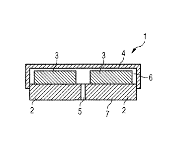
Now a first embodiment of the present invention will be
described with reference to Figures 1 and 2. Figure 1
schematically shows a pole piece 1 in a sectional view. One can
see in Figure 1 a base plate 2 with an opening 5, two magnets 3
and a protective cover 4. The base plate 2 and the protective
cover 4 may be made of steel or stainless steel.
The magnets 3 are fixed to the base plate 2, for instance by
glue. The base plate 2 has an opening 5 which is located
CA 02630659 2008-05-07
200622202 Auslandsfassung
7
between the magnets 3. The magnets 3 are covered by the
protective cover 4 which is connected to the base plate 2. In
the present embodiment, the protective cover 4 is soldered to
the base plate 2. However, the protective cover 4 can also be
fixed to the base plate 2 by other suitable means, for
instance by gluing or welding. The joint between the
protective cover 4 and the base plate 2 is hermetically
sealed.
The magnets 3 and the protective cover 4 are not directly in
contact. The protective cover 4 is connected to the base
plate 2 so as to form an interior cavity 6 between the
protective cover 4 and the base plate 2. This interior cavity
6 is in flow connection with two openings 5 which are
situated between the two magnets in the base plate 2. In
Figure 1 only one of the two openings is visible.
Both openings are shown in Figure 2, which schematically
shows the pole piece 1, as it is shown in Figure 1, in a
bottom view. One can see in Figure 2 the bottom side 7 of the
base plate 2. The base plate has two openings 5 which are
both connected to the interior cavity 6, as shown in Figure
1. Further, one can see in Figure 2 the protective cover 4
which surrounds the base plate 2.
After the fixation of the magnets 3 to the base plate 2, e.g.
by gluing, the protective cover 4 is, for example, soldered
to the base plate 2. Then one of the openings 5 is connected
to a vacuum pump via a valve and the other opening 5 is
connected to a silicone rubber reservoir via a valve.
Alternatively to silicone rubber also epoxy resin can be
used.
First the valve to the silicone rubber reservoir is closed
and the valve to the vacuum pump is open. The interior cavity
6 is now evacuated by the vacuum pump. After this the valve
to the vacuum pump is closed and the valve to the silicone
rubber reservoir is opened. Due to the vacuum in the interior
CA 02630659 2008-05-07
' 200622202 Auslandsfassung
8
cavity 6 the silicone rubber is sucked into the interior
cavity 6. Then both openings 5 can be opened until the
silicone rubber is cured. After curing of the silicone rubber
the openings 5 may be left open if the filling mass is able
to close these openings when it is cured. Alternatively, the
openings 5 may be closed again, for instance by a cap.
Now a second embodiment of the present invention will be
described with reference to Figure 3. Elements corresponding
to elements of the first embodiment will be designated with
the same reference numerals and will not be described again.
In Figure 3 a pole piece 1 is schematically shown in a
sectional view. The pole piece 1 comprises a base plate 2, a
magnet 3 and a protective cover 4. The magnet 3 is glued to
the base plate 2. The protective cover 4 covers the magnet 3
without touching the magnet 3 and is fixed to the base plate
2 by welding. The joint between the protective cover and the
base plate provides a hermetical seal. Between the magnet and
the protective cover an interior cavity 6 is formed.
The base plate 2 comprises an opening 5 which is connected to
the interior cavity 6 besides the magnet 3. Further, the
protective cover 4 also comprises an opening 8 which is
located as far as possible from the opening 5 in the base
plate 2. Preferably, the opening 5 in the base plate 2 is
located at one side of the magnet 3 and the opening 8 in the
protective cover 4 is located at the opposite side of the
magnet 3.
To manufacture the pole piece 1 first the demagnetised magnet
3 is fixed to the base plate 2 by gluing. The base plate may
be made of steel or stainless steel. Then the protective
cover 4 is fixed to the base plate 2 by gluing, soldering or,
like in the present embodiment, by welding so as to provide a
hermetically sealed joint between the protective cover 4 and
the base plate 2. Further, the protective cover 4 is
connected to the base plate 2 so as to leave a space or an
CA 02630659 2008-05-07
= 200622202 Auslandsfassung
9
interior cavity 6 between the magnet 3 and the protective
cover 4.
The opening 8 in the protective cover 4 is connected to a
vacuum pump and the opening 5 in the base plate 2 is
connected to a filling mass injection device, for example a
epoxy resin or silicone rubber reservoir. The interior cavity
6 between the protective cover 4 and the base plate 2 is now
evacuated using the vacuum pump through the opening 8 in the
protective cover 4. Meanwhile the injection mass, which may
be epoxy resin or silicone rubber, is sucked into the
interior cavity 6 through the opening 5 in the base plate 2.
When the interior cavity 6 is completely filled with the
filling mass the openings 5 and 8 can be closed, for example
by a cap. The openings 5 and 8 may alternatively be left open
if the filling mass is able to close them after curing. Now
the filling mass is cured. After curing of the filling mass
the magnet 3 can be magnetised.