Note: Descriptions are shown in the official language in which they were submitted.
CA 02630950 2008-05-23
WO 2007/073075 PCT/KR2006/005553
Description
REINFORCEMENT METHOD AND REINFORCEMENT
STRUCTURE OF THE CORRUGATED STEEL PLATE
STRUCTURE
Technical Field
[1] The present invention relates, in general, to a method and structure for
reinforcing a
corrugated steel plate structure and, more particularly, to a reinforcement
method and
reinforcement structure, in which a liner having a predetermined width and
height is
provided on one surface of a corrugated steel plate constituting a corrugated
steel plate
structure having a span of at least 15m, thus increasing the axial strength
and bending
strength of the steel plate structure, enhancing the industrial usefulness of
the structure,
reducing the number of construction steps and the number of steps for
processing the
liner, thus reducing the construction time and the construction cost.
Background Art
[2] Generally, to fabricate a corrugated steel plate structure, which has been
variously
used as a material of an underground passage, an irrigation channel, a drain,
an
embankment cell, a bank revetment drain, a roof, or a warehouse, a plurality
of steel
plates having predetennined thickness and width are bent and formed into
various
shapes, and are assembled with each other in an axial direction to form a
tunnel shape.
[3] When the size of a desired corrugated steel plate structure is small, one
corrugated
steel plate which has been subjected to a bending process may be used.
However, when
the size of a desired corrugated steel plate structure increases, a plurality
of corrugated
steel plates, which have been separately subjected to respective bending
processes with
high bending ratios, are used such that the steel plates overlap and are
assembled with
each other through an assembly process, such as a bolting process, thus
producing a
desired structure.
[4] Further, in an effort to increase the load carrying capacity of a thin
steel plate by
evenly distributing a load or shock, which is applied to the thin steel plate
in a side
direction, a latitudinal direction, a longitudinal direction or any direction,
to
surrounding areas, the thin steel plate is preferably subjected to a crimping
process,
thus forming a corrugated steel plate having alternating furrows and ridges.
[5] To construct a structure using the corrugated steel plates, the ground on
which the
structure is supported is dug to a predetermined depth for laying the
foundation. After
laying the foundation, molds and reinforcing bars are arranged. Thereafter,
anchors and
a channel are laid, and concrete is placed prior to curing the concrete. After
the
concrete has been completely cured, the molds are removed from the channel.
2
WO 2007/073075 PCT/KR2006/005553
[6] After removing the molds from the channel, a plurality of first corrugated
steel
plates is fixed in the channel using locking members, such as bolts and nuts,
such that
the lower ends of the first steel plates are perpendicular to the channel.
Thereafter,
second corrugated steel plates are bolted to the first corrugated steel plates
at locations
between the first corrugated steel plates, thus forming a desired corrugated
steel plate
structure.
[7] However, the conventional corrugated steel plate, constituting the
corrugated steel
plate structure, is produced through a crimping process, in which a thin steel
plate is
crimped to form alternating furrows and ridges that extend parallel to each
other. Thus,
when the corrugated steel plate is used in a short structure, the corrugated
steel plate
may be successfully used. However, when the corrugated steel plate is used in
a long
structure having a span of at least 15m, the corrugated steel plate structure
has a
reduced longitudinal sectional area. Thus, the resistance of the structure
against the
compressive force is reduced, and thus part of the structure may be easily
broken.
[8] To solve the above-mentioned problems, H-beams or ribs may be installed
outside
the corrugated steel plate, thus reinforcing the structure. However, to
install an H-beam
or a rib outside a corrugated steel plate, the H-beam or the rib is suspended
over the
corrugated steel plate using a crane, and workers must conduct manual work,
such as
bolting work, thus being excessively time-consuming and expensive. Further,
because
the corrugated steel plate has a reduced longitudinal sectional area, the same
problem
as that described above occurs.
Disclosure of Invention
Technical Problem
[9] Accordingly, the present invention has been made keeping in mind the above
problems occurring in the related art, and an object of the present invention
is to
provide a method and structure for reinforcing a corrugated steel plate
structure, in
which a liner having a predetennined width and height is provided along the
outer
surface of a corrugated steel plate constituting a corrugated steel plate
structure, thus
increasing the axial strength and bending strength of the steel plate
structure, so that
the corrugated steel plate can be safely used in a structure having a span of
at least 15m
, enhances the industrial usefulness of the structure, reduces the number of
construction
steps and the number of steps for processing the liner, and thus reduces the
con-
struction time and the construction cost.
Technical Solution
[10] In order to accomplish the above object, in an aspect, the present
invention provides
a method of reinforcing a corrugated steel plate structure using a liner
provided on one
surface of a corrugated steel plate, the reinforcing method using the liner
comprising:
CA 02630950 2008-05-23
3
WO 2007/073075 PCT/KR2006/005553
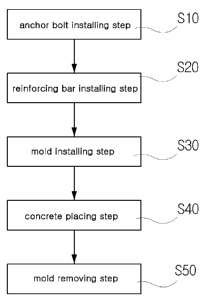
an anchor bolt installing step S 10 of forming an anchor bolt insert hole in
the surface
of the corrugated steel plate and installing an anchor bolt in the anchor bolt
insert hole
such that the upper end of the anchor bolt protrudes from the surface of the
corrugated
steel plate to a predetermined height; a reinforcing bar installing step S20
of fastening
a reinforcing bar to the anchor bolt, which protrudes from the surface of the
corrugated
steel plate, using a wire; a mold installing step S30 of mounting a mold to
the anchor
bolt using a nut such that the reinforcing bar, which has been installed above
the
surface of the corrugated steel plate, is covered by the mold; a concrete
placing step
S40 of placing concrete inside the mold, which has been installed on the
surface of the
corrugated steel plate; and a mold removing step S50 of removing the mold
after the
concrete, which has been placed inside the mold, has been cured.
[11] Further, in the method of reinforcing the corrugated steel plate
structure, the mold
installing step S30 may comprise: placing a sea140 between the mold 30, which
has
been mounted on the surface of the corrugated steel plate 10, and the surface
of the
corrugated steel plate 10; and reinforcing the mold 30, which has been mounted
on the
surface of the corrugated steel plate 10, using a support bar 50 having
externally-
threaded parts 51 formed on opposite ends of the support bar 50 and engaging
with
respective locking nuts 52.
[12] Further, in another aspect, the present invention provides a structure
for reinforcing
a corrugated steel plate structure A using a liner 20 provided on one surface
of a
corrugated steel plate 10, the reinforcing structure using the liner 20
comprising: an
anchor bolt insert hole 13 formed in each of a furrow 11 and a ridge 12 of the
corrugated steel plate 10; an anchor bolt 21, 21', which is mounted to each of
the
anchor bolt insert holes 13 such that the lower end of the anchor bolt 21, 21'
is securely
mounted to the anchor bolt insert hole 13 and an upper end of the anchor bolt
protrudes
outside the corrugated steel plate 10 to a predetermined length; concrete 60,
which has
been placed and cured along the outer surface of the corrugated steel plate 10
having
the protruding anchor bolt 21, 21' such that the concrete 60 has a
predetermined width
and height; a reinforcing bar 22 fastened to the anchor bolts 21 and 21' using
a wire 23
inside the concrete 60; a support bar 50 securely placed inside the cured
concrete 60 at
a position above the reinforcing bar 22, thus being fixed by the cured
concrete 60; and
a waterproof paint 26 applied to the exterior surface of the concrete 60 to a
pre-
determined thickness.
Advantageous Effects
[13] As described above, the present invention provides a concrete liner,
which has a
predetermined width and height and is formed along the outer surface of a
corrugated
steel plate constituting a corrugated steel plate structure, thus increasing
the sectional
CA 02630950 2008-05-23
4
WO 2007/073075 PCT/KR2006/005553
area of the structure and increasing the axial strength and the bending
strength of the
structure, so that the corrugated steel plate can be safely used in a
structure having a
span of at least 15m, thus enhancing the industrial usefulness of the
structure.
[14] Further, the present invention reduces the number of construction steps
and the
number of steps for processing the liner, and thus reduces the construction
time and the
construction cost.
Brief Description of the Drawings
[15] FIG. 1 is a flowchart of the method of reinforcing a corrugated steel
plate structure
according to the present invention;
[16] FIG. 2 is an exploded perspective view of a structure, which has been
reinforced
through the method of reinforcing the corrugated steel plate structure
according to the
present invention;
[17] FIG. 3 is a sectional view of FIG. 2; and
[18] FIGS. 4 through 8 are views illustrating the sequential steps of the
method of re-
inforcing the corrugated steel plate structure according to the present
invention.
Best Mode for Carrying Out the Invention
[19] Herein below, preferred embodiments of the present invention will be
described in
detail with reference to the accompanying drawings.
[20] The corrugated steel plate structure, to which the method of reinforcing
the
corrugated steel plate structure according to the present invention may be
adapted, is
produced by forming alternating furrows and ridges on a steel plate, having a
pre-
detennined thickness and width, through a crimping process, thus fonning a
corrugated
steel plate, and by securing the corrugated steel plate to anchors and
channels, which
have been installed in the foundation, using bolts and nuts. Thus, a desired
corrugated
steel plate structure having a tunnel shape can be obtained.
[21] The present invention increases the sectional area of the corrugated
steel plate,
which constitutes the tunnel-shaped structure. Thus, the present invention
increases the
axial strength and the bending strength of the structure, and thus a large-
sized and
stable structure can be provided. In the present invention, a liner 20 is
provided on a
surface of a corrugated steel plate 10.
[22] To form the liner 20, a plurality of anchor bolt insert holes 13 having
the same
diameter is formed in the furrows 11 and the ridges 12 of the surface of the
corrugated
steel plate 10 through a drilling process. An anchor bolt 21, 21' is installed
in each of
the anchor bolt insert holes 13, which are formed in the corrugated steel
plate 10, such
that the upper end of the anchor bolt 21, 21' protrudes from the surface of
the
corrugated steel plate 10 to a predetermined height, thus laying the
foundation.
[23] Thereafter, a reinforcing bar installing step S20 is executed so as to
fasten a re-
CA 02630950 2008-05-23
5
WO 2007/073075 PCT/KR2006/005553
inforcing bar 22 to the anchor bolts 21 and 21', which protrude from the
surface of the
corrugated steel plate 10, using wires 23. Thus, it is possible to prevent the
resulting
liner 20 from being removed from the surface of the corrugated steel plate 10
and to
increase the rupture strength of the liner 20. Next, a mold installing step
S30 is
executed to fasten a mold 30 to the anchor bolts 21 and 21' using a nut 24
such that the
mold 30 covers the reinforcing bar 22, which has been installed above the
surface of
the corrugated steel plate 10.
[24] In the above state, to place concrete 60 inside the mold 30, an inlet
having a pre-
determined diameter or a predetermined surface area must be formed in an
uppermost
mold 30. Further, to prevent the leakage of water from the placed concrete 60
to the
atmosphere through gaps between the corrugated steel plate 10 and the mold 30,
a seal
40 is preferably interposed between the surface of the corrugated steel plate
10 and the
mold 30, which has been installed on the surface of the corrugated steel plate
10. The
sea140 comprises a louver having a groove 41, as shown in FIGS. 6 and 7. The
grooves 41 of the louvers engage with the respective edges of the mold 30.
[25] Further, in the mold installing step S30, the mold 30 is supported by a
support bar
50, which has externally-threaded parts 51 on opposite ends thereof and is
inserted into
and fastened to side panels 31, which extend parallel to the axial direction
of the
corrugated steel plate 10, using locking nuts 52. Thus, the liner 20 can be
prevented
from being deformed at the opposite sides thereof.
[26] Thereafter, a concrete placing step S40 is executed to place concrete 60
inside the
mold 30, which has been installed on the surface of the corrugated steel plate
10. When
the placed concrete 60 has cured, after the passage of a predetermined lengthy
period
of time, a mold removing step S50 is executed to remove the mold 30 from the
cured
concrete 60, and thus a concrete liner 20 having a predetermined width and
height is
provided along the outer surface of the corrugated steel plate 10.
[27] When the liner 20 has sufficiently dried after the mold 30 is removed
from the liner
20, waterproof paint 26 is coated on the surface of the liner 20 to a
predetermined
thickness, thus protecting the surface of the liner 20.
CA 02630950 2008-05-23