Note: Descriptions are shown in the official language in which they were submitted.
CA 02630994 2008-05-08
TITLE: METHOD AND APPARATUS FOR PROVIDING LANYARD SECUREMENT
TO A TRANSPORT TRAILER
Field of the Invention
[0001] This invention relates to safety harnesses and lanyards and more
particularly to
the securement of lanyards to transport trailers.
Background of the Invention
[0002] Transport trailers are large, generally rectangular enclosures mounted
on a frame
and wheels for the carting around of goods by truck or "tractor". A typical
transport trailer would
measure about 114 inches high, 102 inches wide and 53 feet in length. the
bottom of the trailer
would be several feet of the ground. Accordingly the top of the transport
trailer may well be 15
feet or so from the ground.
[0003] On occasion it is necessary for a worker to access the top of a
transport trailer for
such things as cleaning or repairs to the top. It is also on occasion,
necessary for a worker to
access the sides of a transport trailer for similar reasons. In either case,
the worker is at risk of
falling from a considerable height which could cause severe injury or death.
[0004] One manner of safeguarding workers at risk of falling is through the
use of a
safety harness worn by the worker and a lanyard (safety line) connected to the
safety harness at
one end and having a lanyard hook at the opposite end. The worker secures the
lanyard to a
securement near where the worker is working to provide a limited range of
mobility yet arrest a
fall beyond the range should the worker be so unlucky. Unfortunately, at least
heretofore, safety
harnesses and lanyards haven't been effective for use with transport trailers
because of the lack
of securement points on a typical transport trailer.
[0005] It is an object of the present invention to provide a solution to the
problem of
securing a lanyard to a transport trailer.
Summary of the Invention
[0006] An apparatus is provided for providing lanyard hook attachment to a
transport
trailer. The strap has first and second opposite ends with respective
securement means connected
CA 02630994 2008-05-08
-2-
to the first and second ends. Tensioning means are connected to the strap
between the first and
second ends for applying tension to said strap to urge the first and second
ends and in turn the
respective securement means toward one another. The respective securement
means are
configured to grip opposite edges of the transport trailer in response to the
tensioning of the strap
to secure the strap to the transport trailer at least to such an extent as to
support the weight of a
worker hanging from a lanyard mounted to the strap.
[0007] The lanyard may be looped about a run of the strap for slideable
movement
therealong.
[0008] The strap may be provided with at least one tie-off loop secured
thereto for
receiving a lanyard hook connected to the lanyard.
[0009] The securement means may be "J-hooks".
[0010] The tie-off loop may extend along the strap to permit the lanyard hook
to slide
along the strap in response to the worker moving along the transport trailer.
[0011] A plurality of tie-off loops may be provided.
[0012] The apparatus may have a plurality of straps.
[0013] Where the apparatus has a plurality of straps each including tensioning
means and
securement means as described above, the plurality of straps may be secured to
each other so as
to extend transversely relative to one another.
[0014] The straps may be of woven webbing made from polyester, nylon, or
combinations thereof.
[0015] The straps may preferably be of from 2 inches to 4 inches in breadth.
[0016] A method is provided for providing lanyard hook attachment to a
transport trailer.
The method comprises the steps of-
(i) providing an apparatus as described above;
CA 02630994 2008-05-08
-3-
(ii) securing the apparatus to a transport trailer by mounting the respective
securing means over the opposite edges of the transport trailer and
tensioning the tensioning means to apply tension to the strap thereby
causing secure gripping of the opposite edges of the transport trailer with
the securement means;
(iii) securing the lanyard to the apparatus for either slideable or non-
slideable
movement therealong.
Description of Drawings
[0017] Preferred embodiments of the present invention are described below with
reference to the accompanying illustrations in which:
[0018] Figure 1 is a perspective view of a first embodiment of an apparatus
according to
the present invention secured to a transport trailer;
[0019] Figure 2 is a perspective view of a second embodiment of an apparatus
according
to the present invention secured to a transport trailer;
[0020] Figure 3 is a perspective view of a third embodiment of an apparatus
according to
the present invention secured to a transport trailer; and,
[0021] Figure 4 is a perspective of a fourth embodiment of an apparatus
according to the
present invention secured to a transport trailer.
Description of Preferred Embodiments
[0022] An apparatus according to the present invention is generally indicated
by
reference 10 in the accompanying illustrations. Although different embodiments
are illustrated
and described, the different embodiments are largely built up of similar basic
structural elements
and operate according to similar principles. Accordingly similar reference
numerals are used to
identify similar elements or components.
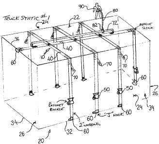
[0023] As best illustrated in Figure 2, a transport trailer 20 has a top face
22, opposite
side faces 24 and opposite end faces 26. Typically a ledge 30 extends about
the transport trailer
CA 02630994 2008-05-08
-4-
20 where the top face 22 meets the side faces 24 and end faces 26, in other
words, about the
perimeter of the top face 22. The presence of the ledge 30 facilitates
gripping of the transport
trailer 20 about the perimeter of the top face 22.
[0024] The apparatus 10 has at least one strap 40 having a first end 42
opposite a second
end 44. The strap 40 may be of webbing woven from polyester or nylon, a
combination of the
two or any webbing such as typically approved for use in safety vests and fall
arrest straps. The
strap 40 may have a breadth of two to four inches.
[0025] Tensioning means 50 are provided along the strap 40 between the first
and second
ends, 42 and 44 respectively. The tensioning means act to shorten and
accordingly tension the
strap by urging the first end 42 towards the second end 44. Suitable
tensioning means include,
without limitation, ratcheting spools such as used with tie-down straps.
[0026] Connected to the first end 42 and second end 44 are respective
securement means
such as the "J" shaped hooks referred to as "J-hooks" 60. The J-hooks 60 are
shaped to grip
opposite edges of the transport trailer 20.
[0027] "Opposite edges" refers to any two edges of the transport trailer 20
which are on
opposite sides or ends and are defined by the junction between the top face 22
and either the
opposite side faces 24 or end faces 26. "Opposite edges" also refers to
opposite lower edges 32
of the side faces 24 or opposite lower edges 34 of the end faces 26.
[0028] Preferably, for use with transport trailer 20 having a ledge 30, the J-
hooks 60 have
a profile conforming to that of the ledge 30 to permit the ledge 30 to nest
within the J-hook 60
for secure attachment.
[0029] The apparatus 10 is secured to the transport trailer 20 by placing the
J-hooks 60
over opposite edges of the transport trailer 20 and tensioning the strap 40
via the tensioning
means or ratchet 50 to cause the securement means or J-hooks 60 to grip the
opposite edges of
the transport trailer. While this may be done with one strap 40, preferably
the apparatus 10 will
be made up of a plurality of straps 40 each equipped with a respective
tensioning means or
ratchet 50 and securement means 60. This is discussed in more detail below.
CA 02630994 2008-05-08
-5-
[0030] The apparatus 10 further includes one or more tie-off loops 70 secured
to the
straps 40 to provide securement for a lanyard 80 connected to a safety harness
90. Alternatively,
the lanyard 80 may have a loop or hook 82 which may be fastened about the
strap 40. Preferably
though tie-off loops 70 are provided. The tie-off loops 70 may be relatively
short (a few inches)
such as the loops illustrated in Figures 1, 3 and 4 or run along a
considerable length of the strap
40 such as illustrated in Figure 1.
[0031] Although a single strap 40 may be utilized, this will have limitations
in the
number and location of tie-off loops and hence will limit the range within
which a worker 90
may operate. Preferably a plurality of straps will be utilized to provide
enhanced security by way
of additional J-hooks 60 for gripping the transport trailer 20 and the ability
to provide a much
more extensive coverage of the transport trailer 20 thereby having lanyard
attachment
capabilities nearby for virtually anywhere on the transport trailer 20 that a
worker 90 may need
to access.
[0032] Figure 1 illustrates an apparatus according to the present invention
having three
transversely extending straps 40 sewn to one longitudinally extending strap
40. The transversely
extending straps 40 are secured to opposite lower side edges 32 of the
transport trailer 20. The
longitudinally extending strap 40 is secured at a diagonally opposite upper
front edge 36 and
lower rear edge 34 of the transport trailer 20.
[0033] The longitudinally extending strap 40 has a relatively long tie-off
loop 72
extending along much of the length of the top face 22 of the transport trailer
20 enabling the
worker 90 access over much of the top face 22. The transversely extending
straps 40 have shorter
tie-off loops 70 principally for workers working on the opposite side faces 24
of the transport
trailer 20.
[0034] Figure 2 illustrates an embodiment of the present invention having two
transversely extending straps 40 secured to one longitudinally extending strap
40. All
securements to the transport trailer 20 in this case are to the ledge 30
extending about the top
face 22 of the transport trailer 20. The lanyard 80 is illustrated as being
secured about the
longitudinally extending strap 40 which in this case lacks any tie-off loops.
The transversely
extending straps 40 each have two respective tie-off loops 70 along their
lengths.
CA 02630994 2012-03-28
I
-6-
[0035] Figure 4 illustrates an embodiment of the present invention which is
similar to the
Figure 2 embodiment but has a pair of parallel longitudinally extending straps
40 secured to the
transversely extending straps 40 rather than just one as in the Figure 2
embodiment. The lanyard
80 is fastened about a run 74 of the strap 40 for slideable movement
therealong.
[0036] Figure 3 illustrates an embodiment of the present invention having two
spaced
apart transversely extending straps 40 secured to opposite of the lower edges
32 of the transport
trailer 20. Tie-off loops 70 are provided along the length of the straps 40.
The Figure 3
embodiment differs from the other embodiments described above in that it
doesn't directly
connect the lanyard 80 to the straps 40 or tie-off loops 70. Instead a
lifeline 110 is secured
between tie-off loops 70 on the two straps 40 and the lanyard is mounted on
the lifeline 110. The
lifeline 110 has snap hooks 112 at each end for securement to the tie-off
loops 70 and an adjuster
114 along its length for adjusting its length.
[0037] Abrasion sleeves 120 may be provided around the straps 40 where the
straps
extend over an edge of the transport trailer 20 to avoid chafing.
[0038] The above invention is described in an illustrative rather than a
restrictive sense.
Variations may be apparent to persons skilled in such arrangements without
departing from the
spirit and scope of the invention as defined by the claims set out below.
CA 02630994 2008-05-08
-7-
Parts List
apparatus
trailer
22 top face
24 side faces
26 end face
ledge
32 lower edge of sides
34 lower edge of ends
36 upper front edge
strap
42 first end of strap
44 second end of strap
ratchet (tensioning means)
J-hook (securement means)
tie-off loops
72 long loops
74 "run" of straps
lanyard
82 lanyard hook or loop
worker