Language selection

Search

Patent 2631521 Summary

Third-party information liability

Some of the information on this Web page has been provided by external sources. The Government of Canada is not responsible for the accuracy, reliability or currency of the information supplied by external sources. Users wishing to rely upon this information should consult directly with the source of the information. Content provided by external sources is not subject to official languages, privacy and accessibility requirements.

Claims and Abstract availability

Any discrepancies in the text and image of the Claims and Abstract are due to differing posting times. Text of the Claims and Abstract are posted:

  • At the time the application is open to public inspection;
  • At the time of issue of the patent (grant).
(12) Patent: (11) CA 2631521
(54) English Title: REMOTE CONTROLLED DEADBOLT DOOR LOCKING SYSTEM
(54) French Title: SYSTEME DE VERROUILLAGE DE PORTE TELECOMMANDE A PENNE DORMANT
Status: Deemed expired
Bibliographic Data
(51) International Patent Classification (IPC):
  • E05B 47/02 (2006.01)
  • H02J 7/00 (2006.01)
(72) Inventors :
  • ALIFERIS, PETER (Canada)
  • LEGENY, GABOR (Canada)
(73) Owners :
  • ALIFERIS, PETER (Canada)
  • LEGENY, GABOR (Canada)
(71) Applicants :
  • ALIFERIS, PETER (Canada)
  • LEGENY, GABOR (Canada)
(74) Agent: NA
(74) Associate agent: NA
(45) Issued: 2012-06-19
(22) Filed Date: 2008-05-14
(41) Open to Public Inspection: 2009-11-14
Examination requested: 2008-05-14
Availability of licence: Yes
(25) Language of filing: English

Patent Cooperation Treaty (PCT): No

(30) Application Priority Data: None

Abstracts

English Abstract


The remote controlled deadbolt door locking system (the "unit") is designed to
be an add-on
locking mechanism for doors. The unit is designed to be mounted onto the
bottom corner of a
door, and when in the engaged position, it prevents said door from being
opened. The unit uses a
DC motor to move a shaft into a hole drilled into the floor. The unit is
mounted onto the door with
four carriage bolts through the door, and a mounting plate on the outside of
the door. The unit's
circuit warns the user if there is a low battery condition or battery failure,
and/or the shaft does not
fully engage upon closing. The operation of the unit is accomplished through a
keyless entry
device. In this way, the unit acts just like a simple dead bolt, but one that
can be locked from
outside.


French Abstract

La présente invention se rapporte à un système télécommandé de verrouillage de porte à penne dormant (l'unité), conçu en tant que mécanisme de verrouillage ajouté pour des portes. L'unité est prévue pour être montée sur le coin inférieur d'une porte et, à la position d'engagement, empêche l'ouverture de ladite porte. L'unité comporte un moteur à c.c. pour déplacer un arbre dans le trou foré dans le plancher. L'unité est montée sur la porte avec quatre boulons mécaniques traversant la porte, ainsi que sur la plaque de montage à l'extérieure de la porte. Le circuit de l'unité avertit l'utilisateur si la batterie est faible ou en panne, et/ou l'arbre ne s'engage pas complètement lors de la fermeture. L'utilisation de l'unité se fait par le biais d'un dispositif d'entrée sans clé. Ainsi, l'unité sert effectivement de simple penne dormant, mais cet élément peut être verrouillé de l'extérieur.

Claims

Note: Claims are shown in the official language in which they were submitted.


Claims

The embodiments of the invention in which an exclusive property or privilege
is claimed are
defined as follows.


1. An electromechanical device that is mounted on the inside of a door,
capable of being
controlled from either side of the door, where a steel shaft is completely
external to the
door, comprising:

- a steel shaft;

- a bushing for receiving the steel shaft;

- a DC motor, including a worm attached to the output shaft, that engages the
steel shaft
in order to extend or retract the steel shaft into or out of the bushing;

- two electrical contact switches to determine the engaged or the retracted
positions of
the steel shaft;

- a contact mounted to the steel shaft, which contacts either one of the two
electrical
contact switches;

- a steel support stamping which securely holds and guides the steel shaft;

- the worm, for driving a worm gear, that is attached to the output shaft,
wherein when
driven by the worm, the worm gear engages meshing teeth on one side of the
steel shaft
through a slot of the steel support stamping to drive the steel shaft.

- a steel support stamping which securely holds and guides said shaft, and
through
which the door is securely held closed;

- a printed circuit board (PCB), to control the DC motor according to user
input;
- a primary battery and a backup battery that supply power to the PCB, which
automatically switches power from the primary battery to the backup battery in
the event
of a low power condition in the primary battery;

- a warning system with audible alarm and two warning LED's, contolled by the
PCB to warn user of a low battery condition and engagement problems;


- an overtimer circuit, whose function is to reverse the DC motor to retract
the steel shaft,
if the steel shaft does not reach the fully extended position in a set period
of time;

- a failsafe system controlled by the PCB to retract the steel shaft, and
prevent future
operation if the primary and backup batteries fall to a low level;

- a cover having two holes through which the two warning LED's can be seen,
and
also having one cutout to allow the steel shaft to pass through;

- a base plate to which the electromechanical device is assembled;

- a mounting plate through which 4 carriage bolts hold the electromechanical
device onto
the door, which also keeps the door securely closed;

- a spacer which mounts between the device and the door, whose function is to
allow the shaft and bushing centerline to be placed at the correct location
from
the bottom of the door frame for proper installation.

Description

Note: Descriptions are shown in the official language in which they were submitted.


CA 02631521 2010-04-26

Remote Controlled Deadbolt Door Locking System - Specifications
This invention relates to a remotely operated electromechanical deadbolt
mechanism used to
secure a door. It is intended, but not limited to use for home residences.

The common deadbolt, especially when mounted onto the bottom of a door and
engaged into a hole drilled in the floor (a foot-lock), is inaccessible from
the outside, making it
one of the simplest and safest methods for securing a door. The disadvantage
of the
deadbolt, however, is that it cannot be locked from outside of the house,
unlike the common
tumbler lock or a keypad lock. Whilst these locks offer the homeowner the
ability to lock the
door from the outside, they leave themselves open to tampering, and are also
not as strong
as the deadbolt when the door is subjected to an impact force.

Our solution to this problem is the amalgamation of the advantages of each of
the
aforementioned devices: the simple deadbolt and the simple lock. Our invention
involves a
simple motorized deadbolt unit, which, in response to a unique signal from a
remote control,
keypad entry, fingerprint, retina, or voice recognition device, will either
extend the bolt -
locking the door, or retract the bolt - unlocking the door. In this way, the
door can now be
locked and unlocked from either inside or outside the house.

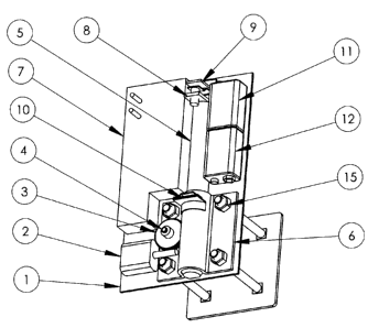
The complete unit is shown in figures 1 and 2. Fig 1 shows the fully assembled
unit as it
would be mounted on a door: with mounting plate (13), carriage bolts (14), and
cover (16).
Figures 3,4, and 5 show the unit mounted onto a door. The following is a list
of the main
components of the unit:

1. base plate
2. motor
3. reducing worm gear (driving gear)
4. gear mounting stud
5. shaft (bolt)
6. shaft securing plate
7. circuit
8. shaft mounted contactor
9. retract limit switch contact
10. extend limit switch contact
11. main battery
12. backup battery


CA 02631521 2010-04-26
13. mounting plate
14. carriage bolts
15. mounting nuts
16. cover
17. offset spacer
18. bushing

I Mounting the unit to the door is accomplished by using a provided template
to mark the
locations of the four through-holes at the bottom corner of the door. The four
holes are
drilled through the entire thickness of the door, and with cover (16) removed,
the unit is
then mounted to the inside of the door with four carriage bolts (14), mounting
nuts (15),
and mounting plate (13). An offset spacer (17) is placed between the door and
the base
plate (1). The template is again used to mark the precise location of the hole
in the floor
whilst the door is closed. This hole then receives a metal bushing (18), into
which the bolt
(5) will engage. The bushing is held down to the floor by a provided adhesive.
(See Figs.
3, 4, and 5)

II The overall function of the unit is to slide the shaft into the receiving
bushing mounted in
the floor. This is accomplished after the circuit-mounted receiver, receives
the 'lock'
signal from the transmitter, which is accomplished by pressing the appropriate
button on
the sending unit by the operator. (similar to a door lock/unlock keychain for
automobile
door locks).

III Once the circuit (7) receives said signal from the transmitter, it turns
the motor (2) on. The
motor shaft has an attached worm, which meshes with the appropriate reducing
worm
gear (3), which in turn, meshes with teeth cut into the side of the shaft (5).
The shaft
securing plate (6) has a slot through the side facing the gear (3), which
allows said gear
to operate the shaft (5). The shaft then extends linearly downward. A flat
milled along one
side of the shaft, perpendicular to the gear teeth, prevents the shaft from
rotating. The
shaft is held in place, and thus holds the door in place by the shaft securing
plate (6).

IV The motor runs and hence the shaft extends in this way until the end of
travel limit switch
is triggered when the shaft mounted contactor (8) reaches the switch for the
extended
position (10). At this time, the motor turns off. The door is now secured with
the engaging
end of the shaft inside the floor bushing, and the other end held to the door
by the shaft
securing plate.


CA 02631521 2010-04-26

There may arise a time when the shaft does not fully engage into the bushing.
(e.g. the door is not closed properly). If this happens, the shaft will not
extend all
the way, and thus the shaft contactor does not make contact with the end of
travel switch. If this contact does not occur within the nominal closing time,
the
circuit will sense this condition via an overtimer circuit and automatically
reverse
the motor and retract the shaft back to the fully retracted (unlocked)
position (see
part V for unlocking sequence) At the same time, an audible alarm will warn
the
operator that something is wrong. This alarm will sound for a set period of
time.

V When the operator wishes to unlock the door (ie disengage the unit), he/she
presses the
unlock button on the remote controller, and the motor runs in reverse and
retracts the
shaft until the shaft mounted contactor (8), reaches the end of travel limit
switch for the
retracted position (9), at which point the circuit turns the motor off. We are
now back at
section II.

Additional Specifications

The power to the unit is provided by a standard battery. A secondary battery
of the same
type provides power if the main battery falls to a low level, or in the
unlikely event that the
main battery fails. When either of these two conditions is reached, the
circuit
automatically switches to the backup battery and an LED turns on to show that
the
battery needs to be replaced. This light will remain on until said battery is
replaced. In
the event that both batteries fall to a low level, both LED's will be lit, and
also an audible
alarm will sound until at least one of the batteries is replaced. In addition,
the unit will
retract the bolt to the unlocked position and prevent any future operations
until the
batteries are replaced. This prevents the unwanted condition of the unit
getting stuck in
the locked position when the operator is outside of the house.

Other mounting possibilities

Owing to the unit's straightforward method of mounting, it is possible to
mount the unit
sideways on the door, so that the bolt engages horizontally into a clasp
mounted to the
door frame, instead of into a floor mounted bushing. Although this
configuration is
intrinsically weaker than the proposed floor mounted one, it may be more
desirable for
those who do not wish to drill their floor.

3

Representative Drawing
A single figure which represents the drawing illustrating the invention.
Administrative Status

For a clearer understanding of the status of the application/patent presented on this page, the site Disclaimer , as well as the definitions for Patent , Administrative Status , Maintenance Fee  and Payment History  should be consulted.

Administrative Status

Title Date
Forecasted Issue Date 2012-06-19
(22) Filed 2008-05-14
Examination Requested 2008-05-14
(41) Open to Public Inspection 2009-11-14
(45) Issued 2012-06-19
Deemed Expired 2015-05-14

Abandonment History

There is no abandonment history.

Payment History

Fee Type Anniversary Year Due Date Amount Paid Paid Date
Request for Examination $400.00 2008-05-14
Application Fee $200.00 2008-05-14
Maintenance Fee - Application - New Act 2 2010-05-14 $50.00 2010-05-14
Maintenance Fee - Application - New Act 3 2011-05-16 $50.00 2011-04-13
Final Fee $150.00 2012-04-02
Maintenance Fee - Application - New Act 4 2012-05-14 $50.00 2012-04-02
Maintenance Fee - Patent - New Act 5 2013-05-14 $100.00 2013-04-18
Owners on Record

Note: Records showing the ownership history in alphabetical order.

Current Owners on Record
ALIFERIS, PETER
LEGENY, GABOR
Past Owners on Record
None
Past Owners that do not appear in the "Owners on Record" listing will appear in other documentation within the application.
Documents

To view selected files, please enter reCAPTCHA code :


To view images, click a link in the Document Description column. To download the documents, select one or more checkboxes in the first column and then click the "Download Selected in PDF format (Zip Archive)" or the "Download Selected as Single PDF" button.

List of published and non-published patent-specific documents on the CPD .

If you have any difficulty accessing content, you can call the Client Service Centre at 1-866-997-1936 or send them an e-mail at CIPO Client Service Centre.


Document
Description 
Date
(yyyy-mm-dd) 
Number of pages   Size of Image (KB) 
Cover Page 2009-11-04 1 50
Abstract 2008-05-14 1 30
Description 2008-05-14 2 130
Claims 2008-05-14 2 55
Drawings 2008-05-14 3 51
Representative Drawing 2009-10-19 1 13
Abstract 2010-04-26 1 17
Description 2010-04-26 3 130
Claims 2010-04-26 2 47
Claims 2011-04-13 2 49
Claims 2011-10-20 2 50
Cover Page 2012-05-28 2 47
Prosecution-Amendment 2009-10-27 4 141
Correspondence 2008-06-20 1 12
Assignment 2008-05-14 4 82
Fees 2010-05-14 1 49
Fees 2011-04-13 1 46
Prosecution-Amendment 2010-04-26 7 240
Prosecution-Amendment 2010-10-27 3 129
Prosecution-Amendment 2011-04-13 3 74
Prosecution-Amendment 2011-05-25 2 81
Prosecution-Amendment 2011-10-20 3 74
Correspondence 2011-12-14 1 30
Correspondence 2012-04-02 1 23
Fees 2012-04-02 1 19
Fees 2013-04-18 1 13
Fees 2014-05-15 1 123
Correspondence 2014-05-28 1 21