Note: Descriptions are shown in the official language in which they were submitted.
CA 02631553 2008-05-28
WO 2007/073415 PCT/US2006/031864
RECHARGEABLE VACUUM
WITH REDUCED AC VOLTAGE
Field of the Disclosure
The present invention relates generally to electrical motors that may be
used in consumer rechargeable products, and more particularly to a motor that
accommodates both alternating current and direct current power sources.
Background of the Disclosure
Existing rechargeable devices, such as vacuum cleaners, may use a
direct current (DC) motor that is powered by a rechargeable battery, where the
battery is charged by an auxiliary circuit connected to an alternating current
(AC) power supply, such as a standard wall outlet. When the device is
plugged into the AC power supply, the AC supply is effectively converted to
DC and used to charge the battery while providing power to the DC motor.
When the AC power supply is removed, the battery may continue to provide
DC power to the motor. When AC power is used, the AC is converted into
DC and stepped down to match the battery power level. DC motors using
battery supplied power may be relatively weak compared to AC power motors
using the same outlet source.
In other consumer devices, a universal motor may be used to power the
device. Universal motors accept both AC and DC power without the need for
an AC-DC conversion circuit. These universal motors are usually series
wound circuits in which the motor field coils are connected in series. The
problem with universal motors is that often, the voltage from an AC source is
higher than the voltage from a DC battery, and thus a huge power discrepancy
CA 02631553 2010-03-11
64267-1525
exists in switching between an AC outlet source and DC battery power supply.
This difference in power is very noticeable and further highlights the poor
performance of a universal motor using battery-only power.
Therefore, there is a need to provide a circuit for a rechargeable
motor that will enable the motor to run on both an AC outlet source and DC
battery, preferably with less discrepancy in power when switching between AC
and
DC power.
Summary of the Invention
The claimed method and system provide an electric motor that runs
on AC and DC power with a reduced motor power difference when switching
between an AC power source and a DC power source. The AC voltage to the
motor may be stepped down by using a clipper circuit, while the DC power
supplied to the motor may be increased by switching motor field windings from
a
series wound circuit to a parallel wound circuit.
While the specific method and system will be described to apply to a
vacuum motor embodiment, it is emphasized that this system may be applied to
other consumer devices that utilize electric motors.
In one broad aspect of the invention, there is provided an electric
motor comprising: a rotor having at least two electrical contacts; a stator
having a
first field coil and a second field coil, wherein the first field coil
includes a first end
and second end, the second field coil includes a first end and second end, and
the
first and second field coils are positioned on opposite sides of the stator; a
first
brush and a second brush positioned on opposite sides of the stator wherein
the
first and second brushes make electrical connections to the electrical
contacts on
the rotor as the rotor rotates with respect to the stator; and a switch
arranged to
connect a parallel field coil circuit to a source of DC power and arranged to
connect a series field coil circuit to a source of AC power; wherein the
series field
coil circuit comprises the first end of the first field coil connected to the
first brush,
the first end of the second field coil connected to the second brush, the
second
end of the first field coil connected to a first terminal of the switch and
the second
-2-
CA 02631553 2010-03-11
64267-1525
end of the second field coil connected to a second terminal of the switch; and
the
parallel field coil circuit comprises the first end of the first field coil
connected to
the first end of the second field coil, the second end of the first field coil
connected
to the second end of the second field coil and the second motor brush, and a
third
terminal of the switch connected to the first end of the first field coil and
a fourth
terminal of the switch connected to the first brush.
In another broad aspect of the invention, there is provided a method
for operating an electric motor that includes a series wound field coil
circuit having
a first end of a first field coil connected to a first motor brush, a first
end of a
second field coil connected to a second motor brush, and an AC power supply
connected between a second end of the first field coil and a second end of the
second field coil, and a parallel wound field coil circuit having a first end
of the first
field coil connected to a first end of the second field coil, a second end of
the first
field coil connected to a second end of the second field coil and the first
motor
brush, and a DC power supply connected between the second motor brush and
the first end of the first field coil; the method comprising: switching to the
series
wound field coil circuit when an AC power supply is used and to the parallel
wound field coil circuit when a DC power supply is used.
In yet another broad aspect of the invention, there is provided a
vacuum cleaner comprising: a housing with a suction opening; a debris
collection
unit; an AC power cord; a battery; and an electric motor comprising: a rotor
having
at least two electrical contacts; a stator having a first field coil and a
second field
coil, wherein the first field coil includes a first end and a second end, the
second
field coil includes a first end and a second end, and the first and second
field coils
are positioned on opposite sides of the stator; a first brush and a second
brush
positioned on opposite sides of the stator wherein the first and second brush
make
electrical connections to the electrical contacts as the rotor rotates with
respect to
the stator; and a switch that connects a power source to one of a series field
coil
circuit and a parallel field coil circuit, wherein the power source includes a
first
terminal and a second terminal; wherein the series field coil circuit
comprises the
first end of the first field coil connected to the first brush, the first end
of the second
field coil connected to the second brush, the second end of the first field
coil
-2a-
CA 02631553 2010-03-11
64267-1525
connected to the first terminal of the power source and the second end of the
second field coil connected to the second terminal of the power source; and
the
parallel field coil circuit comprises the first end of the first field coil
connected to the
first end of the second field coil, the second end of the first field coil
connected to
the second end of the second field coil and the second motor brush, and the
power
source connected between the first end of the first field coil and the first
brush.
-2b-
CA 02631553 2008-05-28
WO 2007/073415 PCT/US2006/031864
Brief Description of the Drawings
Fig. I illustrates a perspective view of the front of an electric motor
embodiment of the claimed invention;
Fig. 2 is a top sectional view of the electric motor of Figure 1;
Fig. 3 illustrates a side perspective view of the rotor, winding board,
and lower housing of electric motor of Fig. 1;
Fig. 4= illustrates a top view of the electric motor of Fig. 1;
Fig. 5 is an electro-mechanical diagram of a series wound AC motor
circuit used in an embodiment of the claims;
Fig. 6 is an electro-mechanical diagram of a parallel wound DC motor
circuit used in an embodiment of the claims;
Fig. 7 illustrates a switching apparatus that may be used in an
embodiment of the claims;
Fig. 8 illustrates an electrical diagram of a clipper circuit that may be
used in an embodiment of the claims;
Fig. 9 illustrates a general electrical connection diagram of a clipper
circuit, a battery, a switch and a motor in an embodiment of the claims; and
Fig. 10 illustrates a vacuum cleaner which may include a motor in
accordance with the claimed invention.
-3-
CA 02631553 2010-03-11
64267-1525
Detailed Description
Although the following text sets forth a detailed description of the
claimed invention it is to be construed as exemplary only and does not
describe every possible embodiment. Numerous alternative embodiments
could be implemented, using either current technology or technology
developed after the filing date of this patent, which would still fall within
the
scope of the claims.
It should also be understood that, unless a term is expressly defined in
this patent using the sentence "As used herein, the term is hereby
defined to mean..." or a similar sentence, there is no intent to limit the
meaning of that term, either expressly or by implication, beyond its plain or
ordinary meaning, and such term should not be interpreted to be limited in
scope based on any statement made in any section of this patent (other than
the
language of the claims). To the extent that any term recited in the claims is
referred to in this patent in a manner consistent with a single meaning, that
is
done for sake of clarity only, so as to not confuse the reader, and it is not
intended that such claim term be limited, by implication or otherwise, to that
single meaning.
Referring now to the drawings, and particularly to FIG. 1, an example
of an electric motor 10 is disclosed.. The motor 10 includes a stator 12, a
lower housing 16 (shown on the top in FIG. 1), and an upper housing 24.
-4-
CA 02631553 2008-05-28
WO 2007/073415 PCT/US2006/031864
Supported by the stator 12 is a set of coils, including a first coil 20
forming a
first pole and a second coil 22 forming a second pole. Fastened to the stator
12 is the upper housing 24. An annature,-indicated generally at 26, mounted
on a motor shaft 17 with a commutator 28 is rotatably mounted-by a lower
bearing 27 within the lower housing 16 and an upper bearing 29 within the
upper housing 24, and is rotatable about shaft 17; as is known in the art.
While the described embodiment illustrates only two coils, it should be noted
that any number of coils could be included in the stator and similar parallel
connections can be made between each field coil.
The stator 12 can comprise a series of-laminations 30, each of which is
an annular plate with a large interior opening. The laminations 30 can be
made from cold rolled steel, for example SAE 1010=or 1008, and can be
welded together via plasma welding, as is known in the art. By stacking
several laminations 30, a tubular shape with an exterior annular surface 32
and
- an interior annular surface 34 (See Fig. 2) is created.
As illustrated in Fig. 2, the interior annular surface 34 also includes a
first hook-like protrusion 35 and a second hook-like protrusion 37, each of
which project inwardly towards the center of shaft 17 supporting armature
windings 19. The first protrusion 35 is used to support the first coil 20,
while
the second protrusion 37 is used to support the second coil 22, as is commonly
known. Each of the first protrusion 35 and the second protrusion 37 include
pole tips 39 that define kidneys 41.
-5-
CA 02631553 2008-05-28
WO 2007/073415 PCT/US2006/031864
LOWER HOUSING
The lower housing 16, best seen in Figs. 1 and 3, may be coupled to
the upper housing 24 using a bracket 19 (partially shown in Fig. 3), and
includes structure to receive current from the coils 20, 22 and carry it to
and
from the armature 26.
The lower housing 16 may be made of a non-conductive material, for
example a thermoplastic such as a glass-filled polyester. The lower housing
includes a first brush housing 64 and a second brush housing 66. Disposed
within each brush housing 64, 66 is an electrically conductive brush 65, 67,
1.0 which is urged, usually by a spring-loaded member 69, radially inward
toward
shaft 17 and the armature 26. As is known in the art, the brushes 65, 67
transmit current to the rotating armature 26 through the commutator 28.
PHYSICAL WIRING
Referring now to FIGS. 1-4, the wiring of the motor 10 will be
described. In general, the wiring of motor 10 may consist of a first magnet
wire and a second magnet wire. The first magnet wire may be illustrated (Fig.
4) as having a first start end 70 connected to a terminal connector 71, a
first
field coil portion 72, and a first finish end 73 connected to a connector 74.
The second magnet wire may be illustrated as having a second start end 75
connected to a terminal connector 76, a second field coil portion 78, and a
second finish end 79 connected to a connector 80.
The first magnet wire is wrapped many times around the first hook-like
protrusion 35 of the stator 12, as shown in Fig. 2, to form the first coil 20.
The
-6-
CA 02631553 2008-05-28
WO 2007/073415 PCT/US2006/031864
length of the first magnet wire disposed within the first coil 20 is known as
the
first coil portion 72. The connector 71 may connect the first start portion
with
a terminal wire T3 and a terminal wire T5 and the connector 74 may connect
the first finish portion to a terminal wire T8.
A first brush wire 81 has a first end disposed on a connector 82 and a
second end disposed on the first brush housing 64. The first brush wire 81 is
electrically connected to the first brush 65 slidingly disposed within the
first
brush housing 64 (See Fig. 3), as is known in the art. The connector 82 may
connect the first brush wire 81 to a terminal wire T7.
As shown in FIG. 3, the first brush 65 is urged forward to the motor
shaft 17 and into physical and electrical contact with the commutator 28 and
the armature 26. The armature 26 spins around the axis of shaft 17 while in
contact with the first brush 65.
A second brush 67 is disposed within the second brush housing 66
opposite the first brush housing 64. The second brush 67 is also urged
forward into contact with the armature 26. A second brush wire 77 connects
the second brush housing 66 to the connector 76, such that the second brush
wire and second start wire are electrically contacted. The connector 76 may
connect the second brush wire 77 and second start wire to a terminal wire T12.
The second magnet wire may also be a single wire having a second
finish end 79, a second coil portion 78, and a second start end 75. The second
magnet wire is wrapped many times around the second hook like projection 37
of the stator 12, as shown in Fig. 2, to form the second coil 22. The length
of
the first magnet wire disposed within the second coil 22 is known as the
-7-
CA 02631553 2008-05-28
WO 2007/073415 PCT/US2006/031864
second coil portion 78. The second magnet wire then exits the second coil 22
and is connected to the connector 80. The connector 80 may be connected to a
terminal wire T6.
SERIES AND PARALLEL FIELD COIL CIRCUITS
Fig. 5 illustrates an electrical diagram of an AC series wound field coil
circuit, while Fig. 6 illustrates an electrical diagram of a DC parallel wound
field coil circuit. Generally, an AC power source may be connected through a
switch consisting of a first terminal T8 and a second terminal T6. In'the
series
field coil circuit, the first terminal T8 may be connected to the finish end
73 of
the first field coil 72. The start end 70 of the first field coil 72 may be
connected to a first brush 65. The first brush 65 may electrically contact a
rotor, or armature 26, which may'also electrically contact the second brush
67.
The second brush 67 may be connected to the start end 75 of the second field
coil 78. The finish end -of the second field coil 79 maybe connected to the
second terminal T6, thereby forming a series field coil circuit.
Generally, a DC power source may be connected through a switch
consisting of a terminal T5, a terminal T6, and a terminal T7. In the parallel
field coil circuit, the first terminal T7 may be connected to the first brush
65.
The first brush 65 may electrically contact the rotor 26, which may'also
electrically contact the second brush 67. The second brush 67 may be
connected to the finish end 73 of the first field coil 72. The start end 70 of
the
first field coil 72 may be connected to the second terminal T5,T6 of the
switch. The second brush 67 may also be connected to a start end 75 of a
second field coil 78. A finish end 79 of the second field coil 78 may be
-8-
CA 02631553 2008-05-28
WO 2007/073415 PCT/US2006/031864
connected to the second terminal T5,T6 of the switch, thereby forming a
parallel field coil circuit.
CURRENT FLOW AND USE OF MOTOR
With reference to FIGS. 1-4, the current flow will now be described for
an AC series field coil circuit. Current may be supplied to the motor 10 by a
two terminal power source (not shown). Current flows from a first-power
source terminal through the first finish wire 73 and into the first coil
portion
72 and through the first coil 20. Current then travels out of the first coil
20
and through the connector to the first brush wire 81 and into the first brush
65.
The first brush 65 is electrically conductive and is urged into contact with
the
commutator 28 on the armature 26, thereby supplying current to the armature
26. The energized an-nature 26 is also in contact with the second brush 67
inside the second brush housing 66. Current flows through the second brush
67 and into the second brush wire 77 that is connected to the second start
wire
75. Current then flows from the second start wire 75 into the second coil
wire,
thereby energizing the second coil 22. Finally, current flows through the
second finish wire 79 out to a second power source terminal. As is known in
the art, a current flowing through the first coil 20 and the second coil 22
generates a magnetic field. The an-nature 26, with current flowing through it,
is induced to rotate about the shaft 17.
The current flow for a parallel DC field coil circuit will now be
described. Current may be supplied to the motor 10 by a two terminal DC
power source (not shown). Current flows from a first power terminal through
-9-
CA 02631553 2008-05-28
WO 2007/073415 PCT/US2006/031864
the first brush wire 81 to the first brush 65. The first brush 65 is
electrically
conductive and is urged into contact with the commutator 28 on the armature
26, thereby supplying current to the armature 26. The energized armature 26'
is also in contact with the second brush 67 inside the second brush housing
66.
Current flows through the second brush 67 and into the second brush wire 77.
Current then flows from the second brush wire through the first finish wire
73,
through first coil portion 72, and through the first coil 20. Current then
flows
out of the first coil 20 through the first start wire 70 and to a second
terminal
of the power source.
In this parallel circuit, the first finish wire 73 is also connected to the
second start wire 75 and the second finish wire 79 is connected to the first
start
wire 70, thereby forming a parallel coil combination. Thus, current also flows
from the second brush 67 to second start wire'75 into the second coil portion
78, thereby energizing the second coil 22. Current then flows through the
second finish wire 79 to the power source. As in the series circuit, the first
brush 65 supplies current to the armature 26 and the energized armature 26 is
also in contact with the second brush 67 inside the second brush housing 66.
Current flows through the second brush 67 and into the second brush wire 94
and into the parallel coils. As is known in the art, a current flowing through
the first coil 20 and the second coil 22 generates a magnetic field. The
armature 26, with current flowing through it, is induced to rotate about the
shaft 17. Further, the physical arrangement of the coils and the polarity of
the
DC power supply may determine the direction of rotation, as known in the art,
and thus in an embodiment of the claims, the arrangement of the coils or the
-10-
CA 02631553 2008-05-28
WO 2007/073415 PCT/US2006/031864
polarity of the DC supply may be adapted so that the direction of rotation of
the armature is the same for both AC and DC power.
Fig. 7 illustrates a switch that may be used to connect between the AC
and DC power sources, on the one hand, and the series field coil circuit and
the parallel field coil circuit, described above, on the other. The switch may
be a four pole, double throw switch that is commercially available. However,
other types of switches having different configurations may also be used, as
known to those skilled in the art. The 4-pole, double throw switch may consist
of 12 terminals T1-T12, that may be divided into three rows. In a first
position, the switch may connect Ti with T5, T2 with T6, T3 with T7, and T4
with T8. In a second position, the switch may connect T5 with T9, T6 with
TI0, T7 with TI 1, and T8 with T12.
In one embodiment of the claims, a DC powered parallel circuit may
be switched to an AC powered series circuit using the switch of Fig. 7. In
this
embodiment, the terminal wires of Fig. 5, T3, T5, T6, T7, T8, and T12 are
connected to respectively marked terminals of Fig. S. Further, a first and
second terminal of an AC power source may be connected to T2 and T4 of
Fig. 7, and a first and second terminal of a DC power source may be
connected to T9 and TI 1. In this embodiment, T9 is also connected to T10.
When the switch is in the first position, the AC series circuit described
above
is connected. :. When the switch is in the second position, the DC parallel
circuit described above is connected.
-11-
CA 02631553 2008-05-28
WO 2007/073415 PCT/US2006/031864
CLIPPER CIRCUIT
Fig. 8 illustrates a clipper circuit that may be used to reduce the voltage
of an AC power source. The clipper circuit may consist of a DIAC Ql and a
TRIAC Q2, (sometimes called an alternistor or a thyristor). This circuit may
be designed to cutoff the peak voltage of an alternating signal, thus being
called a clipper circuit. Generally, a TRIAC Q2 does not effectively conduct
current between its main terminals Pl, P2 unless a gate voltage is applied at
its
gate G terminal. Thus, an AC signal across the TRIAC Q2 will maintain its
voltage unless a gate signal is applied, thereby shorting any signal across
its
main terminals P1,P2 and clipping the signal voltage. The DIAC Q1 blocks
applied voltages in either direction until a breakover voltage is applied.
Thus,
the level of clipping is directly related to the breakover voltage of the DIAC
Q1. Resistor R3 and C2 form a snubber circuit which is used to reduce the
rate of change of voltage across the TRIAC. Variable resistor R2 and.
capacitor Cl are used to control the rate of change of voltage across the
DIAC,
thus providing control over the timing of the clipping mechanism.
The circuit of Fig. 8 may be connected across an AC power source that
maybe applied to the field coil circuits described above. In another
embodiment, the clipper circuit may be further used to charge a battery used
to
supply DC power to the parallel circuit. In this embodiment, a further
rectifying circuit, as is known in the art, may be implemented with the
clipper
circuit of Fig. 8 before supplying a voltage to the batteries, as illustrated
in
Fig. 9.
-12-
CA 02631553 2008-05-28
WO 2007/073415 PCT/US2006/031864
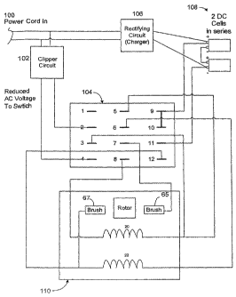
Figure 9 illustrates an overall embodiment of the claimed system. A
wall outlet AC power source 100 is fed into a clipper circuit 102. The clipper
circuit reduces the effective voltage of the AC power and is channeled to a
switch 104. A rectifying circuit 106 may also be connected to the AC power
source to provide a DC charging current to a set of batteries 108. In one
embodiment, the rectifying circuit charges the batteries while the switch 104
is
arranged to channel AC power to the motor. As further illustrated in Figure 9,
switch 104 provides connections to the motor 110. Specifically, the switch
104 provides connections for a series wound circuit connected to AC power
.10 when the switch is in a let position and provides connections for a
parallel
wound circuit connected to the batteries when the switch is in a right
position.
The circuits and connections are the same as those described above.
Figure 110 illustrates a vacuum cleaner embodiment of.the claims.
Similar components of Figure 9 are labeled in Figure 10. In the vacuum
cleaner embodiment of Figure 10, AC outlet power is channeled into the
vacuum cleaner device through a power cord 100, which connects to a
combination clipper circuit 102 and rectifying circuit 106. A DC battery 108
is connected to the rectifying circuit 106. A wire cord provides the AC and
DC power to a switch 104. The switch is coupled to the electric motor 110 as
illustrated in Figure 10 where the wiring may be connected in a similar
fashion
as illustrated in Figure 9.
Existing motor systems may rely solely on a DC series wound motor
having low power output or a universal motor that may only match the power
-13
CA 02631553 2008-05-28
WO 2007/073415 PCT/US2006/031864
of a DC battery, i.e., the AC is brought down completely to a DC power level
(which may be typically much weaker than original AC power level).
The claimed motor switches from a series wound circuit to a parallel
wound circuit when DC operating power is used. Switching from a series
wound to parallel wound circuit decreases the effective impedance of the field
winding, thereby increasing DC operating power. When the motor is
operating on AC power, a series field coil circuit is used to increase
impedance and decrease operating power. A clipper circuit may be used
across the AC power supply to further reduce the effective AC power supplied
to the motor when the motor is operating on AC. The claimed motor increases
the average power performance of the motor while decreasing the power
discrepancy in motor operation when switching between AC and DC power.
Many modifications and variations may be made in the techniques and
structures described and illustrated herein without departing from the spirit
and scope of the present claims., Accordingly, it should be understood that
the
methods and apparatus described herein are illustrative only and are not
limiting upon the scope of the claims.
-14-