Note: Descriptions are shown in the official language in which they were submitted.
CA 02632012 2008-06-04
METHOD AND APPARATUS FOR REDUCING NOX EMISSIONS
IN A GAS BURNER
Background of the Invention
Field of the Invention
This invention relates to a burner, particularly to one for burning a gaseous
fuel,
and further relates to a method of burning a gaseous fuel in a manner to
produce
combustion gases having a low content of nitrogen oxide. Hereinafter, nitrogen
oxides,
which are primarily nitric oxide and nitrogen dioxide, are collectively
referred to as
"NO
.
X "
Description of the Prior Art
Major environmental and other problems have been encountered in the production
of flue gases containing high contents of NOX. The NOx tends to react under
atmospheric
conditions to form environmentally unacceptable conditions, including the
widely known
phenomena known as urban smog and acid rain. In the United States and
elsewhere,
environmental legislations and restrictions have been enacted, and more are
expected to
be enacted in the future, severely limiting the content of NOx in flue gases.
In U.S. Pat. No. 4,874,310, granted Oct. 17, 1989 to Selas Corporation of
America, the assignee hereof, a controlled primary air inspiration gas burner
was
disclosed, in which the introduction of control primary air was controlled in
order to
provide a substantial reduction of the content of nitrogen oxides in the flue
gas. Such a
burner includes extra piping for the introduction and control of the primary
air, and this
sometimes introduces expense and possible complications, especially in furnace
installations utilizing a very large number of burners. Other endeavors have
been made
to reduce the content of NOx in furnace flue gases but many have been found
unattractive
in view of their requirement of too much operator attention, and in view of
the need for
CA 02632012 2008-06-04
extremely attentive control in order to assure that there will be no violation
of existing
environmental laws.
It has been the general indication in the prior art for burners that reduced
NOX
content can be obtained by avoiding secondary air, by using substantially
entirely primary
air, and by firing the burner as close as possible to its maximum firing
capacity.
Additionally, it has also been known that NOX emissions can be reduced in some
instances
in premix burners by creating a screen of premix combustion products,
introducing
secondary gaseous fuel for admixture with the screen, and exposing the
secondary air to
the mixture for reaction with the secondary gaseous fuel. Such a burner is
disclosed in
0 U.S. Pat. No. 5,044,931, granted Sept. 3, 1991 to Selas Corporation.
Other endeavors have also been made to reduce the content of NOX in furnace
flue
gases. For example, it has also been known in the prior art to attempt to
reduce NOx
gases by utilizing an inspirated stage combustion burner, such as that
disclosed in U.S.
Patent No. 5,271,729, granted December 21, 1993 to Selas Corporation. This
burner
includes two staged premix units with one unit running very lean and the
second unit
extending into the furnace and running very rich, the combination being
stoichiometric.
However, this burner is limited to 50% hydrogen by volume to prevent backfire.
External flue gas recirculation systems have also been used to reduce NOX
emissions, such as the systems disclosed in U.S. Patent Nos. 5,347,958 (issued
September 20, 1994); 5,326,254 (issued July 5, 1994); 5,259,342 (issued
November 9,
1993); 4,659,305 (issued April 21, 1987); 3,957,418 (issued May 18, 1976) and
3,817,232 (issued June 18, 1974). However, these systems are expensive to
produce and
to operate. Consequently, a system is needed which can reduce NOx emissions,
efficiently and reliably, and at low cost.
-2-
CA 02632012 2008-06-04
It is very important to be able to obtain the greatest reduction of NOX
content
possible while burning a high hydrogen content fuel, and that even in the
event of
operator error environmental laws will not be violated and the further
operation of the
plant and its equipment will not be enjoined by governmental action.
Accordingly, a
burner is needed which significantly reduces NOX gases produced and which is
capable
of burning a fuel with high fractions of hydrogen without backfire and a
subsequent
increase in NOx.
Objects of the Invention
It is therefore an object of the invention to provide a burner which can
reduce NOx
0 emissions efficiently and reliably while burning a high hydrogen content
fuel.
It is another object of the invention to provide a burner which can reduce NOx
emissions without the need for expensive external flue gas recirculating
systems.
It is yet another object of the invention to provide a burner having a low NOx
emission which is less influenced by tramp air, changes in firing rate, and
hydrogen
content in the fuel.
Still another object of the present invention is to provide a burner in which
the
majority of the gas and a little air are sent in one direction along the walls
and most of
the air and a minority of the gas are sent in another direction forwardly into
the furnace,
causing a dilution of the air with the flue gases within the furnace to
achieve a significant
reduction in NOX emissions without the large cost of external flue gas
recirculation.
Other objects and advantages of this invention, will become apparent to oile
of
ordinary skill in the art from the description of the invention contained
herein, the
appended claims and the drawings.
-3-
CA 02632012 2008-06-04
Drawings
Fig. 1 is a sectional view showing a first embodiment of the invention
utilizing a
nozzle mix burner.
Fig. 2 is a detailed view of the burner tip of Fig. 1.
Fig. 3 is a sectional view of a second embodiment of the invention utilizing a
premix burner tip.
Fig. 4 is a cross-sectional view along line A-A of the embodiment shown in
Fig.
2.
Fig. 5 is a sectional view of another embodiment of the present invention
which
0 is used in a vertical furnace having a floor burner.
Fig. 6 is a cross-sectional view along line B-B of Fig. 4.
Summary of the Invention
The present invention includes a method and apparatus for reducing NOX
emissions
in a gaseous fuel burner used in a furnace. The burner includes a burner
supply means
for supplying fuel gas and primary air to the furnace, having a combustion end
located
within the furnace for projecting the fuel gas into the furnace for combustion
which
produces spent flue gases, a secondary air supply means for supplying
secondary air to
the burner, and a recirculation means for mixing the secondary air with the
spent gases
inside the furnace space to produce a diluted air, which is recirculated and
mixed with
the partially combusted primary fuel gas to reduce NOx emissions.
In one embodiment of the present invention, a nozzle mix burner is used,
having
primary jets for projecting the majority of fuel gas or premix outward
radially into the
furnace and secondary jets for projecting a minority of fuel gas forward
axially into the
furnace. The secondary jets are capable of mixing the secondary air with the
spent gases
inside the furnace to produce the recirculated air. Alternatively, jet tubes
may be used
-4-
CA 02632012 2008-06-04
to supply fuel gas or premix to the furnace in which a separate secondary jet
is used to
mix secondary air with the spent gases. Additionally, the invention can be
used in a
vertical furnace having a floor burner and secondary air vents for mixing and
recirculating the secondary air with the spent gas inside the furnace.
Detailed Description of the Invention
It will be appreciated that the following description is intended to refer to
the
specific forms of the invention selected for illustration of the drawings, and
is not
intended to define or limit the invention, other than as in the appended
claims.
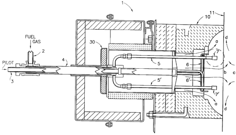
Turning now to the specific form of the invention illustrated in the drawings,
Figs.
9 1 and 2 disclose a first embodiment of the invention. The burner 1 may
include fuel gas
inlet 2 and pilot gas inlet 3 which are connected in a conventional manner to
conduit 4
within the burner. Fuel gas inlet 2 may alternatively include a blower or
inspirator to
form a premixture. Gas or premix is then supplied to the furnace by way of gas
injector
tubes 5 and 5, which are also conventionally connected to conduit 4 and which
extend
into the furnace. Pilot injector tubes 6 and 6' are also connected in a
conventional
manner to conduit 4 for supplying pilot gas to the furnace from pilot gas
inlet 3. Ports
7 and 7', containing primary jet 8 and secondary jet 9 are attached to
injector tubes 5 and
5' to project fuel gas radially and axially into the furnace, respectively.
Air may enter the burner and the furnace through air shutter 30 which works in
a conventional manner to supply air to the system. Primary air, designated by
path (a)
travels along burner block 10 and furnace wall 11 for combustion of the fuel
gas
projected from primary jet 8. Secondary air, designated by path (b), may
travel inwardly
of ports 7 and 7' for combustion with the fuel gas projected from secondary
jet 9. Spent
flue gas descends along path (c) and is recirculated by being mixed with the
secondary
air to form diluted air, which is caused to flow outwardly along path (d)
along furnace
-5-
CA 02632012 2008-06-04
wall 11 where it is burned with the primary air and the fuel gas projected
from primary
jet 8.
The operation of this embodiment of the invention is as follows. Pilot gas may
enter through pilot gas inlet 3, moving forwardly through conduit 4, and pilot
gas tubes
6, to form a vortex of burning gas within burner block 10. This vortex of gas
may be
combusted to raise the temperature within burner block 10 to a suitable level
for
operating the burner. This is normally about 1600 F, but can be varied
depending upon
the application. The use of a vortex pilot, which is optional, has significant
safety
advantages in that it can be used at operating temperatures below the self-
ignition point.
0 Primary fuel gas or premix may enter through primary fuel gas inlet 2 and is
transported forwardly along conduit 4 into gas injector tubes 5 and 5' to
ports 7 and 7'.
A majority of the gas is then projected outward radially from primary jet 8 to
be
combusted with primary air traveling along path (a). The angle at which the
gas is
projected from primary jet 8 is not particularly restricted. However, the gas
jet angle
should be chosen to keep visible flame away from process tubes while also
keeping the
gas injector tubes protected within the plane of the wall. The jets should
also be angled
to reduce any refractory erosion which may occur from gas running along the
furnace
wall at high speed.
Additionally, the positions of the gas injector tubes 5 and 5' and ports 7 and
7' are
not particularly limited but are preferably outwardly of the center of the
burner towards
the sides, outside the secondary air flow. Although this is mechanically less
convenient,
the outside position of the jets significantly reduces high speed flame
flutter, pulsing and
combustion noise, and makes the burner significantly less sensitive to changes
in firing
rate, fuel composition, excess air, projection, and block shape. Also, the
position of the
gas tubes within the air stream ingeniously aids in cooling the gas jets. This
embodiment
-6-
CA 02632012 2008-06-04
of the present invention also has the significant benefit over traditional
burners that it may
operate at significantly lower gas pressures.
A minority of gas is projected from secondary jet 9 forwardly into the furnace
to
be combusted with secondary air flowing along path (b). The amount of gas
projected
from the secondary jets is not particularly restricted but is preferably less
than 25 % and
greater than 10% of the total fuel gas used. The combustion of the gas from
the
secondary jets causes the secondary air to be mixed with spent flue gases
descending
along path (c), which are primarily the result of the combustion of the gas
from the
primary jets. Good mixing of air and spent gases is believed to occur due to
micro-
0 explosions of the gas combusted from the secondary jets. The forcible
mixture of the
secondary air and the spent flue gases forms a diluted air which is
recirculated along the
furnace wall along path (d) to be combusted with the primary air and the fuel
gas
projected from the primary jets, causing a significant reduction in NOX gases
produced
during this combustion.
Alternatively, as depicted in Figs. 3 & 4, primary fuel may enter through
primary
fuel inlet 13 to be premixed with primary air entering through primary air
shutter 16 in
a conventional manner. The premix is then transported through venturi 14 into
tip 15 to
which it is connected in a conventional manner. Tip 15 has a plurality of
primary jet
tubes 19 at its combustion end, located within the furnace, for projecting the
premix
radially into the furnace for combustion along furnace wall 20.
Secondary fuel may then be transmitted forwardly along a secondary fuel inlet
17
having secondary jets 22 at its combustion end, located within the furnace.
The
secondary jets project the secondary fuel forwardly into the furnace. The
angle at which
the secondary fuel is projected is not particularly restricted but is
preferably less than 30
from center. Secondary air enters through secondary air shutter 18, flowing
forwardly
-7-
CA 02632012 2008-06-04
into the furnace through annulus 21 in a conventional manner, and entering the
furnace
along path (b)'. Annulus 21 may also include snout 23, extending forwardly
into the
furnace to aid in directing the secondary air flow and protecting the tubes.
The exact
length of snout 23 is not particularly restricted but should be long enough to
adequately
aid in the forcible mixture of the secondary air with the flue gases.
The secondary air is burned with the fuel projected from secondary jets 22 and
is
thereby mixed with spent flue gases descending along path (c)' to form a
diluted air
which is recirculated along path (d)'. The diluted air is combusted with the
premix
projected along the furnace wall from primary jet tubes 19, causing a
significant reduction
0 in the NOX gases produced.
Additionally, as shown in Figs. 5 and 6, a vertical furnace may be used with a
floor-mounted burner. A fuel rich primary air and fuel premix is transported
forwardly
along primary fuel inlet 24 through burner array 25 situated within furnace
floor 28 to
supply fuel gas to the furnace. Primary air thus enters along path (a)" as
part of the
premix. The premix is then projected into the furnace and burned, heating
fluid
contained in process tubes 29. This combustion produces flue gases, some of
which leave
the furnace by way of furnace stack 26, with the remainder recirculating and
descending
along path (c)". Inside the furnace, secondary air is pulled into the furnace
by the draft
through secondary air ports 27 along path (b)". The secondary air entering
through
secondary ports 27 is thereby mixed and recirculated with the spent flue gases
traveling
along path (c)" along path (d)" to be burned with the premix. This results in
a
significantly reduced amount of NOX gases.
In previous conventional burners, primary fuel and air may inadvertently mix
to
a small degree with descending furnace gases; however, it has been found that
sufficient
NOx reduction is not realized in these burners. This is because the spent
gases must be
-8-
CA 02632012 2008-06-04
sufficiently mixed and recirculated with secondary air to create a
sufficiently diluted air
to be mixed with the primary fuel air for combustion. In conventional boilers
this was
sometimes done by recirculating gases after they had left the furnace.
However, it has
ingeniously been discovered that if the dilution of the air with spent gases
could be
accomplished inside the furnace, a significantly larger reduction in NOX could
be obtained
without the large cost of an external flue gas recirculation system.
By producing a gaseous fuel burner in the manner set forth in the appended
claims
and described herein, it is possible to significantly reduce the NOX emissions
produced
by combusted gases in the furnace. It is believed that the lowest NOX would be
obtained
0 if the air is well mixed with the spent gases inside the furnace before
returning to mix and
burn with the fuel. With forced air or with lean premix projected
perpendicular to the
furnace wall, good mixing may be nearly realized. This does not occur with
conventional
draft air systems because draft air is normally very lazy, and thus usually
cannot itself
provide sufficient mixing of the furnace atmosphere, resulting in pockets of
high oxygen
and thus higher NOx. It has been ingeniously discovered that the apparatus and
method
of the present invention will allow for sufficient mixing of the gases inside
the furnace,
leading to significantly reduced NOx.
In traditional burners, the leaner nozzle-mix flames created very high NOX
gases.
However, when secondary jets were added, it was unexpectedly discovered that
the NOX
was significantly lowered. This unusual behavior is believed to be attributed
to the fact
that the secondary gas jets create micro-explosions which generate enough
energy to
forcibly mix the air with the furnace atmosphere, also resulting in
significantly lower NO,,
emissions.
Moreover, it was found that if the gas jets were simply a low pressure premix
and
attached to the burner tip, the NOx would increase as predicted in
conventional burner
-9-
CA 02632012 2008-06-04
systems (a lean nozzle-mix burner creates the highest NOx). When compressed
air was
projected from the secondary jets instead of secondary fuel, there was no
change in NOX
emissions. Thus, it is believed that it is the micro-explosions in the nozzle-
mix burner
which provide the energy needed to forcibly mix the secondary air with the
spent gases,
leading to a significant reduction in NOx gases. The limit of secondary fuel
appears to
be the tolerance of the furnace for these micro-explosions. However, secondary
fuel
should not be required with a system such as the vertical furnace shown in
Fig. 4, since
the air can be drawn and mixed directly with the spent gases inside the
furnace.
Significant NO, reduction can also be obtained if a forced air system is used.
0 In the situation where a premix burner is utilized, a premix ratio of 2:1 to
5:1
seems optimum for high temperature furnaces, while higher ratios will add
flame stability
for lower temperatures. The benefits of using a premix burner here are
twofold; large
holes are possible with less chance of plugging with mill scale and dirt, and
the air acts
as a coolant to prevent gas cracking and plugging of the holes. The air may
also be
staged with lean premix when the fuel composition is backfire resistant. The
main benefit
here is lower NOx through better inixing and a more distributed heat release.
Although this invention has been shown and described in relation to particular
burners, it will be appreciated that a wide variety of changes may be made
without
departing from the spirit and scope of this invention. Various configurations
and burner
types may be used. For example, a nozzle-mix burner may be used with a forced
air
system without the use of secondary jets. Additionally, the burner may be used
with
various types of gas fuels such as propane, methane or hydrogen mixtures.
Certain
features shown in the drawings may be modified or removed in specific cases,
and
secondary passageways and controls and other mechanical features may be varied
or
dispensed with without departing from the spirit and scope of the invention.
Accordingly,
-10-
CA 02632012 2008-06-04
the scope of the invention is not intended to be limited by the foregoing
description, but
only as set forth in the appended claims.
-11-