Note: Descriptions are shown in the official language in which they were submitted.
CA 02632077 2008-05-23
HEARING ASSISTANCE DEVICE WITH CAPACITIVE SWITCH
Field of the Invention
The present patent application relates to switches used in hearing assistance
devices, and in particular to a hearing assistance device with one or more
capacitive
switches.
Background
Hearing assistance devices include hearing aids, and other devices which
benefit
hearing. In the case of hearing aids, some of the more generally important
design
considerations include low power consumption, limited and sometimes difficult
dimensions, ease of manufacture, comfort, and ease of use. One area of
particular concern
is how to operate hearing aids devices in view of shrinking package sizes,
limited power,
and an increasingly more adult population with limited or diminishing manual
dexterity.
There is a need in the art for improved switches that afford a user easy
switching
without false switching, and which will not be wasteful of power.
Detailed Description
This disclosure describes how capacitive sensor technology is applied to
hearing
assistance devices, including hearing aids, for switch sensing applications.
Advances in
capacitive sensing technology provide beneficial voltage requirements and very
low
current consumption. The operating principle is based on charge transfer
between two
conducting surfaces placed in close proximity. The two surfaces are any
conductive
material, including, but not limited to, metals and conductive inks. The two
surfaces can
be arranged in a variety of sizes and shapes. A circuit generates a specific
electric signal
that is sent to one surface called the drive electrode. In one embodiment, the
circuit is an
integrated circuit (IC). A resultant electric field is generated between this
drive electrode
and a receive electrode. As a conducting body enters this field (between
electrodes) a
variable signal results at the receive electrode that the IC interprets as a
"switch" actuation.
The cost of this IC is relatively minimal and is in line with mass produced
IC's. The
motivations for adapting charge traiisfer (capacitance) sensing technology
within hearing
aids are many fold. In certain realizations of this switch design, the switch
is much lower
in cost than conventional switches since it can be made for less than a dollar
per switch.
(Present hearing aid switch technology (electromechanical) ranges in price
from $2.00 for
1
CA 02632077 2008-05-23
a simple push button, to $3.00 for a potentiometer.) Capacitive sensing
technology is
more reliable because there are no moving parts to fail or wear. Capacitive
switch designs
can reduce or eliminate case ingress due to conventional electromechanical
controls. Dirt
and moisture entry compromises hearing aid reliability. The elimination of
contaminant
entry points makes possible the manufacture of water resistant hearing aids.
Depending on the placement of the sensing electrodes on the hearing aid, new
ways of user interaction are possible. The user could "locate" a specific area
on the aid to
initiate an action (as is presently done), or, use a swiping/brush like
motion. This latter
mode would eliminate the necessity for an elderly user, with limited
dexterity, to
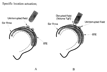
specifically locate and manipulate a small target. FIG. 1A shows a hearing aid
application
which, only for the sake of demonstration, is a behind-the-ear or BTE
technology. It is
understood that the capacitive switch technology could be used in any number
of hearing
assistance designs, and any type of hearing aid. Thus, the technology could be
used in
behind-the-ear, in-the-ear, in-the-canal, and coinpletely-in-the canal
designs. FIG. 1B
shows a disrupted field when the user's finger is in close enough proximity to
the
electrodes. FIG. 2A and FIG. 2B demonstrate the effect of sweeping a finger in
a volume
up and volume down direction, respectively. It is understood that many
configurations
may be employed and that the positions or directions of movement may vary
without
departing from the scope of the invention. Furthermore, the nature of the
fields can be
changed which can affect how close the finger must be to the surfaces of the
switches. For
example, in some embodiments the finger will touch the surface of the hearing
aid to
effect a switch function.
FIG. 3A shows a capacitive sensor to be used to determine when a user has the
hearing aid on his or her ear. In FIG. 3A the aid is on the ear, so the
hearing aid senses
the ear. In FIG. 3B the aid is separate from the ear and no longer senses the
ear. Thus, in
one embodiment this switch can be used to turn the hearing aid off. This
allows for
increased battery power savings as the aid is only on when in use. If a user
forgets to turn
off the hearing aid when not in use, this approach will automatically perform
the "on" and
"off' functions. The switch can serve in some embodiments as an automatic "on"
detector. This same functionality (automatic "ON") can be created in an ITE
hearing
device. (FIGS. 4A and 4B) In this embodiment, the sensors are adapted to touch
the inner
portion of the ear canal when inserted to perform the switching operation.
2
CA 02632077 2008-05-23
In some embodiments a single memory switch function is possible. FIGS. 5A and
5B
demonstrate hearing aid configurations where a single memory switch function
is performed. In
this application a single sensing element is used to cycle through a memory
counter or volume
control counter. Other functions may be implemented with this design and the
examples given
herein are not intended to be limiting or exclusive. It is understood that
this design is not limited
to a BTE approach and that other hearing assistance devices may employ this
design without
departing from the scope of the present subject matter.
FIGS. 6A, 6B, and 6C demonstrate a single memory function in an in the ear
application.
The electrodes at the end of the ITE can be switched with a finger as shown.
Other electrodes and electrode positions may be employed without departing
from the
scope of the present subject matter. With capacitive sensor technology, new
and unique styling
options can be realized. The added metallization (electrodes) could also
provide protection from
cell phone hearing aid interference by acting as a shield to electromagnetic
radiation. Additional
features can be supported with this technology. Multiple sensors, including,
but not limited to,
up/down volume control, telecoil switching, and/or memory select, can enable
second function
capability for the user or audiologist. This would enable, for example, the
audiologist to access
hearing aid parameters that would normally only be available at an
audiologist's office via a
hearing aid progranuner.
Another advantage of the present subject matter is that the elimination of
bulky
electromechanical controls frees up valuable internal volume.
It is understood that many configurations may be employed and that the
positions
or directions of movement may vary without departing from the scope of the
invention.
Different electrode positions and geometries can be employed. Furthermore, the
nature of
the fields can be changed which can affect how close the finger must be to the
surfaces of
the switches. For example, in some embodiments the finger will touch the
surface of the
hearing aid to effect a switch function. Other applications can be performed
and those
listed herein are not intended to be exhaustive or exclusive.
3