Note: Descriptions are shown in the official language in which they were submitted.
CA 02632195 2012-08-27
CONVERTING EXISTING PRIOR ART FUME HOODS INTO HIGH
PERFORMANCE LOW AIRFLOW STABLE VORTEX FUME HOODS
Background of the Invention
Field of the Invention
100021 The present invention relates to fume hood enclosures used for worker
protection. More particularly, the present invention relates to a method and
apparatus for stabilizing the vortex in both existing and new fume hoods.
Description of Related Art
[0003] The Occupational Safety and Health Administration (OSHA) defines a
fume hood as a four sided exhausted enclosure with a front opening for worker
arm penetration. OSHA defines a safe fume hood where worker exposure levels
are below the permissible exposure limits (PELs) accepted by government and
private occupational health research agencies, including the National
Institute of
Occupational Safety and Health (NIOSH). OSHA's position is that it is an
employer's responsibility to make hood adjustments or replace hoods as
necessary
when an employer discovers, through routine exposure monitoring and/or
employee feedback, that the fume hoods are not effectively reducing employee
exposures.
100041 OSHA no longer recommends a given face velocity in feet per minute
(fpm) as a reference to worker protection. This is a reversal of OSHA's early
1980's face velocity position when 125 to 150 Amu was recommended for extreme
toxic material, 100 to 125 fpm for most materials and 75 to 100 fpm for
nuisance
materials, dust, and odors. OSHA's earlier position on face velocity and a
fume
hood's capture protection theory prompted the development of methods to vary
exhaust airflow volume of a fume hood in response to varying sash opening
positions as a way to maintain a fixed face velocity in fpm.
[0005] This type of fume hood, often referred to as a variable air volume
(VAV)
fume hood, had the potential to save energy associated by reducing the amount
of
conditioned make-up air exhausted, and therefore reducing the amount of
CA 02632195 2008-05-13
WO 2007/047367 PCT/US2006/039890
2
conditioned make-up air wasted. For example, at $.10 per kilowatt-hour, and
depending on hood geographical location, it costs approximately $3.50 to $6.50
a
year in the United States to replenish one cubic foot per minute (cfm) of
conditioned make-up air exhausted by the fume hood. An average prior art
constant air volume six foot fume hood will consume over $300,000 in
electrical
energy over its expected lifetime. U.S. Patent No. 4,741,257 pioneered closed-
loop variable air volume fume hood control and patents 4,528,898; 4,705,553;
4,773,311; and 5,240,455 proposed open-loop variable air volume fume hood
control. VAV fume hood technology dominated how fume hoods were operated
through the 1980's and early 1990's.
[0006] Fume hood performance testing prior to OSHA's 1990 Laboratory Worker
Regulation was based on smoke visualization and face velocity measurement.
Smoke bombs or sticks were placed within the fume hood's enclosure, and as
long
as the smoke was not seen exiting the fume hood, it was deemed safe to use at
the
design face velocity. In the early 1990's, a standardized performance tracer
gas
analysis test began to be used to quantitatively measure fume hood performance
in
actual spillage rates in parts per million (ppm). The results have a
relationship to
PELs as determined by NIOSH. The tracer gas testing was developed to address
medical studies linking increased birth defects and cancer rates among
laboratory
workers as highlighted in OSHA's January 31,1990 final rule, 29 CFR Part 1910,
on Occupational Exposures to Hazardous Chemicals in Laboratories. The tracer
gas test takes into account the influence of a worker in front of the fume
hood and
analyzer sampling rate set to replicate the average worker breathing.
[0007] NIOSH fume hood tracer gas cited published studies indicate variable
air
volume and constant volume controlled fume hoods did maintain face velocity
and may have saved energy but did little to improve worker safety. The tests
revealed fume hood designs based on vapor capture face velocity theory failed
to
work as well, and protect workers from spillage, as manufacturers had
suggested.
[0008] NIOSH, whose mission is to provide national and world leadership to
prevent work-related illness and injury, published a position paper in 2000
stating
that fume hood face velocity is not an adequate predictor of fume hood
spillage.
Additionally, tracer gas fume hood studies indicated between 28% and 38% of
the
existing stockpile of 1,300,000 to 1,400,000 hoods in the United States fail
to
CA 02632195 2008-05-13
WO 2007/047367 PCT/US2006/039890
3
meet minimum worker protection, even after attempts to adjust the fume hoods
to
improve performance. At that time, NIOSH's fume hood failure statistics were
based on the American Industrial Hygiene Association's acceptable average fume
hood tracer gas spillage rate of 0.1 ppm. In 2003, the acceptable tracer gas
spillage rate was reduced by half to a rate 0.05 ppm. As a result, NIOSH's
earlier
estimates of unsafe fume hoods have nearly doubled.
100091 The fume hood manufacturer's own trade organization, Scientific
Equipment Furniture Association (SEFA) went on record in their SEFA 1-2001
"Laboratory Fume Hoods Recommended Practices" indicating, "Face velocity
shall be adequate to provide containment. Face velocity is not a measure of
safety." This was the first time the fume hood manufactures abandon the face
velocity capture theory. The SEFA 1-2000 also stated that the "acceptable 0.05
ppm tracer gas spillage level shall not be implied that this exposure level is
safe."
[0010] In terms of fume hood design, the problem was further compounded by
the fact that prior art fume hoods were designed and specified by architects
as
furniture, as opposed to being designed, tested and specified by engineers as
mechanical equipment. The early day fume hoods used stack height and candles
placed on the fireplace smoke shelf to create draft. In the 1800's gas rings
replaced candles and eventually fans and electric motors replaced gas rings.
Changes, such as adding a front vertical single sash window instead of a
hinged
door, were eventually instituted. Prior art vertical or combination sash hoods
all
incorporate a counter balance weight system. Over time, these counterbalancing
sash weight systems fail or become difficult to move. Repairing the counter
balance weight systems require the fume hood be removed, which requires
disconnecting all electrical, plumbing and exhaust services. As this puts the
hood
out of service for a period of time, the sash maintenance is rarely done.
Instead,
when the sash is no longer moveable it is blocked open with the counter weight
balancing system abandoned in place.
[0011] In the 1940's a back exhaust baffle system and streamlined shape
"picture
window" entrance and work surface airfoil were introduced to all hoods, as
illustrated in FIG. 1. Early prior art fume by-pass hood 10 has a vertical
moveable
sash 18 and a picture window utility post 17. There is a rear baffle conduit
28
with a manually adjusted lower slot 36, a fixed center slot 34, and manually
CA 02632195 2008-05-13
WO 2007/047367 PCT/US2006/039890
4
adjusted upper or top slot 32. An exhaust duct 38 is shown on top of the hood
and
a work surface airfoil 22. Because prior art fume hoods only considered face
velocity, no thought was given to the uneven back baffle 28 energy
distribution
caused by the very narrow but wide plenum design, and its negative effect on
internal airflow patterns. The sole purpose for the back baffle was to create
a flat
face velocity, which was subsequently found to be an ineffectual design
premise.
Prior art fume hood picture window design posts, utility water and gas handle
silhouettes and vertical and or horizontal sash guide channels, all
contributed to
cause localized eddies and airflow reversals to form at the utility post
openings.
In the 1950's, an air bypass diffuser 31 was added above the sash opening in
an
attempt to produce uniform face velocity with sash closure.
[0012] To save energy in the 1960's, un-conditioned auxiliary make-up air was
introduced above and around the sash perimeter. United States Patent Nos.
3,025,780; 3,111,077; 3,218,953; 3,254,588; 4,177,717; 4,436,022 and 6,080,058
describe various methods used in introducing un-conditioned outside auxiliary
make up air into a fume hood. One example of an auxiliary make up fume hood
design is shown in FIG. 2. The outside air supply duct 39 is attached to the
full
width supply plenum 40. There is a vertical full width perforated distribution
diffuser 41 in the supply plenum 40 along with air turning vanes 42. The
supply
velocity into the supply slot is 250-300 fpm. The maximum auxiliary air supply
volume is about 50% of the exhaust volume. The utility post 17 is 6 inches
minimum. The depth of these prior art fume hoods were sized so they could be
carried through an average door and placed on a 30" deep by 36" high bench
with
an overall height limited to the average nine and one half foot ceiling. The
height
and depth of the hoods made today are virtually the same size as were made
sixty
years ago. Fume hood depth and aisle spacing requirements tend to drive
laboratory building column spacing, building size and construction cost.
Narrow
fume hoods cost less to manufacture and save building construction costs by
allowing narrower 9-to-I 0 foot column spacing. Manufacturers would vary hood
lengths and sash openings, but such accommodations made no functional
difference.
[0013] To address rising energy costs in the early 70's, horizontal sashes
were
introduced to reduce the size of the sash opening. The prior art horizontal
sash
CA 02632195 2008-05-13
WO 2007/047367 PCT/US2006/039890
fume hoods used either a single track or two track configuration. The prior
art
lower horizontal sash panels were guided in friction channels located in the
sash
handle and used either rollers or a friction channel upper track as guides.
The sash
handle channel tracks are prone to chemical attack and collect debris, thereby
preventing movement and creating turbulence as the horizontal sash is opened.
Unfortunately, the prior art horizontal sash was directed toward energy
savings,
not worker safety. The problem with the prior art horizontal single and two
track
designs was that they required sash panel widths wider than workers could put
their arms around to be used as a full body shield; this was a particular
problem
for shorter workers. Additionally, individual fume hoods are often used by two
or
more workers at the same time and prior art horizontal sash hoods cannot
accommodate multiple workers. As a result, such prior art horizontal sash
design
encourages workers to work in front of an open sash with no splash or
explosion
protection.
[0014] The industry long operated under the erroneous assumption that the fume
hood rear baffle slot adjustments were based on the fume hood's air density.
The
theory was to open the top slot when using lighter than air fumes and open the
bottom baffle slots for heavier-than-air-fumes. Prior art Patents U.S. Patent
Nos.
3,000,292; 3,218,953; 4,177,717; 4,434,711; 4,785,722; and 5,378,195 describe
baffle adjustments and design based on these theories.
[0015] Figure 3, which can be found in the 1999 American Society of Heating
Refrigeration and Air-Conditioning Engineers (ASHRAE) engineering handbook
on laboratories, illustrates the industry's perception at that time of the
airflow
patterns of a typical prior art face velocity capture hood to be laminar
airflow. It
shows laminar air 27 pattern with no vortex when vertical movable sash 18 in
the
raised position. In fact, U.S Patent No. 4,280,400 and U.S. Patent No.
4,785,722
describe fume hood designs to eliminate vortexes from forming. Subsequent
studies by Robert Morris, which resulted in several patents, provided a
reversal to
previously held theory that the fume hood design required eliminating or at
least
minimizing any vortex from forming within the fume hood. Such studies
prompted ASHRAE to remove the laminar airflow figure 3 from their 2003
engineering handbook on Laboratories.
CA 02632195 2008-05-13
WO 2007/047367 PCT/US2006/039890
6
[0016] U.S. Patent No. 5,697,838 to Morris taught that a fume hood effectively
contained fumes when the vortex was stable and fully developed. Vortexes can
be
further described as developing from mono-stable to bi-stable. A mono-stable
vortex is elliptical shaped and attaches to a surface as an air stream is
directed
across that surface. The elliptical shape is caused by a pressure gradient
that
forms across the vortex bubble which deforms the vortex. The mono-stable
vortex has pulling and lifting forces but is restricted to amount of air
volume it can
sustain before it becomes unstable. A bi-stable vortex is symmetrical in shape
and
attaches to two or more surfaces. The bi-stable vortex has better memory and
little force but can sustain a greater air volume and still remain stable.
Because of
cost advantages of making prior art fume hoods narrow, prior art fume hoods do
not create stable vortexes throughout sash movement unless the baffle slot
velocities and exhaust air volumes are automatically controlled. U.S. Patent
No.
5,924,920 to Morris et al. taught how a fume hood could be designed to form a
bi-
stable vortex at a full open sash and then to a mono-stable vortex as the sash
is
closed. One disadvantage was that fume hoods constructed according to the
formula of U.S. Patent 5,924,920 are required to be made deeper.
[0017] Robert Morris, inventor of U.S. Patent Nos. 5,697,838 and 5,924,920,
published studies indicate that 90% of prior art fume hood spillage appears as
puffs at the sash handle which linger at the sash handle when the vortex
collapses.
FIG. 4A and FIG. 4B illustrate what occurs when the vortex collapses and
turbulence occurs. FIG. 4A shows a containing hood with a mono-stable vortex
2.
FIG. 4B shows a non-containing hood with an undefined vortex 3', turbulence
21,
and chemical spillage 4. This issue becomes a greater health risk for the less
than
average 5'8" worker. Designers misinterpreting the observation of fume hood
smoke pattern testing led prior art fume hood designers to focus on the face
velocity and the elimination of the vortex.
[0018] In fact, however, it is during the collapse of the vortex that a hood
fails to
contain fumes. When the vortex fully stabilizes, the fume hood contains fume
vapors. The misunderstanding of the importance of a stable vortex lead
designers
of prior art fume hoods to locate the introduction of bypass diffuser air
above the
sash handle (FIG. 1, 3 and 4) directly into the upper vortex-forming chamber.
Introduction of bypass diffuser air above the sash inhibits a stable vortex
from
CA 02632195 2008-05-13
WO 2007/047367 PCT/US2006/039890
7
forming within the vortex chamber and creates varying airflow patterns with
sash
movement.
[0019] Prior art fume hood designs are based on commonly held notions that a
constant face velocity captures fumes thereby preventing spillage and should
be
maintained with sash window opening and closing by locating the bypass
diffuser
above the sash opening and controlling the exhaust airflow volume. Fume hoods
based on these designs eliminate a stable vortex from forming. Additionally,
prior
art fume hoods baffle slots are adjusted based on fume air density, and the
work
surface airfoil directs air across the work surface towards bottom baffle
exhaust
slot. These design assumptions, as well as others, are not accurate because
they
fail to address the optimum airflow, and therefore the required face velocity
and
internal airflow patterns to prevent fume spillage through containment of the
toxic
fumes.
Summary of the Invention
[0020] EPA studies indicate that if only one half of our prior art population
of
hoods could be fixed to provide the energy savings of high performance low
airflow fume hoods our nation would save 235 trillion BTU's of energy per
year.
This is equivalent to the energy used by 6.2 million households. There is a
need
to convert prior art fume hoods into high performance low airflow fume hoods
without increasing its depth or decreasing the exhaust airflow volume below
the
lower explosive purge limit.
[0021] The present invention describes a work surface airfoil that combines
the
hood's bypass diffuser and a dynamic turning vane airfoil (BDTVA) to support
the development of a stable vortex with sash movement by introducing bypass
diffuser airflow into the fume hood following the principals of conservation
of
momentum. The bypass diffuser airflow exiting the angular and multiple slotted
airfoil must merge with, and turn the fume chamber circulating stable vortex
towards the baffle slots to support a rotational pattern with minimum
turbulence
while expanding or contracting the volume of the stable vortex with sash
movement. The work surface airfoil BDTVA works in combination with the tear
drop sash handle design that will support the required Effective Reynolds
number
(ERe) and take into account the liner roughness condition. This low turbulence
design minimizes Bunsen burner flameouts and allows for even sensitive powder
CA 02632195 2008-05-13
WO 2007/047367 PCT/US2006/039890
8
weighing measurements using sensitive triple beam electronic scales within the
fume hood, all problems with prior art fume hoods. This design also eliminates
the varying velocity and static pressure losses normally encountered with
prior art
fume hoods as the sash is moved.
[0022] These varying velocity and static pressure losses in prior art fume
hoods
create varying exhaust airflows with sash movement. To overcome these varying
exhaust volumes, prior art fume hoods require expensive and high maintenance
duct mounted exhaust airflow volume controls. As described herein, a method of
converting existing fume hoods is provided that eliminates these varying
velocity
and static pressure losses. The need for these airflow controls is eliminated
and
the fume hoods can now be simply locally or remotely hard balanced using a
communication system, supporting today's Green Building Counsels Leadership
in Energy and Environmental Design (LEED) energy efficient, sustainable and
maintainable green laboratory design program.
[0023] The present invention converts a prior art fume hood into a high
performance low airflow stable vortex fume hood without increasing the fume
hoods depth or decreasing the exhaust airflow volume below the minimum lower
explosive purge rate limit.
[0024] The present invention includes a mathematical method to determine the
required ERe to determine all the design elements of the vortex chamber
turning
vane, vortex bypass conduit air volume, work surface airfoil bypass diffuser
and
dynamic turning vane design (BDTVA), rear baffle lower corner slot design and
control sequences to create a high performance low airflow stable vortex fume
hood without empirical field trial and error testing.
[0025] The present invention converts prior art vertical and or combination
vertical/horizontal single and dual track sash hoods into triple track
horizontal or
combination vertical and triple track horizontal sash hoods permitting
simultaneous multiple worker access. The sash windows use clear polycarbonate
material which improves worker safety and acid resistance over standard safety
glass that is supported by guided rollers on the top and one or two removable
tab
guides that insert in the sash handle allowing for easy sash window cleaning
and
hood loading.
CA 02632195 2008-05-13
WO 2007/047367 PCT/US2006/039890
9
[0026] The present invention incorporates a non-pinch point teardrop shaped
sash
handle design with low surface drag coatings, such as Dupont Teflon, that shed
eddy airflow reversals and vortexes from forming in both vertical and
horizontal
sash operation with streamline airflow patterns on all surfaces including self-
cleaning horizontal sash panel guide slots that also eliminate surface eddies
from
forming.
[0027] The present invention incorporates an exhaust damper assembly which can
be inserted from within an existing prior art fume hood exhaust connections
that
includes an inlet nozzle, airflow measuring probe for local and or remote
metering
and balancing communication system, low pressure drop 15:1 turndown linear
damper that rejects up-stream duct generated turbulence and overcomes baffle
conduit static pressure variations.
[0028] The present invention includes conversion kits that include all
necessary
components to convert any style existing prior art fume hood into a stable
vortex
high perforniance low airflow fume hood that can accommodate varying size
prior
art fume hoods without altering the fume hood envelope or customizing the
conversion kit. The articulating rear baffle can be lifted out for cleaning
debris
that collects in baffle conduit. The conversion can be accomplished without
drilling mounting holes into an asbestos liner and can be applied on any size
or
style prior art fume hood.
[0029] The present invention embodiments can be incorporated within a new
fume hood envelope to create a horizontal or combination sash high performance
low airflow stable vortex hood without making the fume hood deeper than a
standard bench cabinet or reducing the exhaust airflow below the lower
explosive
limit.
Brief Description of the Drawings
[0030] FIG. 1 illustrates a prior art hood with a back exhaust baffle system
and
streamlined shape "picture window" entrance and work surface airfoil.
[0031] FIG. 2 illustrates a prior art hood with an auxiliary make-up fume hood
design.
[0032] FIG. 3 illustrates the industry's perception of the airflow patterns of
a
typical prior art face velocity capture hood.
CA 02632195 2008-05-13
WO 2007/047367 PCT/US2006/039890
[0033] FIG. 4A and 4B illustrate what occurs when the vortex is undefined and
turbulence occurs.
[0034] FIG. 5A - 5E illustrate various prior art sash handles.
[0035] FIG. 6 illustrates the side view of a typical prior art fume hood with
sash
fully open.
[0036] FIG. 7 is a chart for determining the Roughness Correction Factor.
[0037] FIG. 8 is a chart for determining the configuration for the conversion
of
prior art hoods into high performance low airflow hoods.
[0038] FIG. 9 is the sequence or configuration for converting a prior art hood
to a
high performance low airflow hood when the prior art hood has a VBA of 0 or
less.
[0039] FIG. 10 is the sequence or configuration for converting a prior art
hood to
a high performance low airflow hood when the prior art hood has a VBA greater
than 0 but less than or equal 30%.
[0040] FIG. 11 is the sequence or configuration for converting a prior art
hood to
a high performance low airflow hood when the prior art hood has a VBA greater
than 30%.
[0041] FIG. 12 is a CFD vector velocity analysis of a formed metal teardrop
handle and dynamic bypass turning vane work surface airfoil.
[0042] FIG. 13A and 13B illustrate two views of an embodiment of the teardrop
shaped handle and horizontal sash.
[0043] FIG. 14 illustrates an embodiment of rear baffle assembly kit.
[0044] FIG. 15A and 15B illustrate two views of one embodiment of a vortex
chamber turning vane kit required for control sequence FIG. 9.
[0045] FIG. 16A and 16B illustrate two views of one embodiment of a vortex
chamber turning vane kit required for control sequence FIG. 10 and FIG. 11.
[0046] FIG. 17 illustrates one embodiment of a kit to field convert an
existing
prior art vertical or combination vertical horizontal sash into a triple track
horizontal sash.
[0047] FIG. 18A, 18B and 18C illustrate multiple views of a horizontal sash
panel
110 for use with the triple track horizontal sash conversion or with newly
constructed hoods.
CA 02632195 2008-05-13
WO 2007/047367 PCT/US2006/039890
11
[0048] FIG. 19 illustrates prior art fume hood velocity profile of the rear
baffle
plenum.
[0049] FIG. 20 illustrates a side view of a bellmouth exhaust damper assembly
inserted into an existing prior art exhaust plenum.
[0050] FIG. 21 illustrates a cross section of a bellmouth exhaust nozzle.
[0051] FIG. 22 illustrates a stable vortex conversion rear baffle velocity
profile.
[0052] FIG. 23A and 23B illustrate two views of one embodiment of a damper
design.
[0053] FIG. 23C-23E provide charts to determine positioning and sizing of the
teeth on the preferred damper design.
[0054] FIG. 24A and 24B illustrate two alternate communication system
sequences for commissioning and balancing FHE system.
Detailed Description
Definitions:
[0055] Access Opening: That part of the fume hood through which work is
performed; sash or face opening.
[0056] Actuable Baffle: A rear baffle system comprised of multiple dampers
allowing for either manual or controlled transfer of a constant exhaust air
volume
by modulating slot opening and closing system
[0057] Airfoil: A horizontal member across the lower part of the fume hood
sash
opening. Shaped to provide a smooth airflow into the chamber across the work
surface.
[0058] Baffle or Rear Baffle: Panel located across the rear wall of the fume
hood
chamber interior and directs the airflow through the fume chamber.
[0059] Balancing: In an air conditioning system is the process of measuring
the
as installed airflow values and making any adjustments to achieve the design
intent.
[0060] Bypass: Compensating opening in a fume hood to limit the maximum air
flow passing through the access opening and or vortex chamber.
[0061] Combination Sash: A fume hood sash with a framed member that moves
vertically, housing horizontal sliding transparent viewing panel or panels.
CA 02632195 2008-05-13
WO 2007/047367 PCT/US2006/039890
12
[0062] Commissioning: In an air-conditioning system it is a process of
ensuring
that systems are installed, functionally tested and capable of being operated
and
maintained to perform in conformity with the design intent.
[0063] Communication System: A control method to maintain a constant fume
hood exhaust airflow thru either remote manual adjustment, shared transducer
auto scanning and sequencing or dedicated control of the exhaust airflow or
static
pressure.
[0064] Conduit: In an air conditioning system a closed channel intended for
the
conveyance of either supply or exhaust air.
[0065] Damper: A device used to vary the volume of air passing through an air
inlet slot, outlet slot or duct.
[0066] Dead Time or Lag Time: The interval of time between initiation of the
input change or stimulus and the start of the resulting response.
[0067] Differential Pressure: The difference between two absolute pressures.
[0068] Diffuser: An air distribution system consisting of deflecting mechanism
discharging air in various directions and planes to promote mixing of the air
supplied into the fume chamber.
[0069] Double or Dual Horizontal Sash: Sash frame with two upper supports and
two bottom supports for dual horizontal sliding transparent viewing panels.
[0070] Dynamic Turning Vane: An active non-physical structure using air jets
to
turn air in a plenum chamber at an angle at a point where airflow changes
direction. Used to promote a more uniform airflow to reduce velocity and
static
pressure losses caused from turbulence.
[0071] Effective Reynolds Number: A Reynolds number required to achieve the
condition the conditions to sustain a stable vortex in the vortex chamber of a
fume
hood.
[0072] Face or Sash Opening: Front Access opening of laboratory fume hood
face opening area measured in width and height, formed through a movable panel
or panels or door set in the access opening/hood entrance. See access opening.
[0073] Face Velocity: Average speed of air flowing expressed in feet per
minute
(FPM) perpendicular to the face opening and into fume hood chamber equal to
the
square root of the fume hood's chambers lower than atmospheric static pressure
times 4003 to correct to average laboratory environmental conditions.
CA 02632195 2008-05-13
WO 2007/047367 PCT/US2006/039890
13
[0074] Flow Coefficient: A constant (CV), related to the geometry of a valve
or
damper, of a given valve or damper opening that can be used to predict flow
rate.
[0075] Fume Chamber: The interior of the fume hood measured width, depth and
height constructed of material suitable for intended use.
[0076] High Performance Low Airflow Hood: LEED defined hood using a
maximum 50 CFM/square foot exhaust air volume, and passing the ASHRAE
tracer gas test with a less than 0.05 PPM spillage at 4 LPM tracer gas release
rate.
[0077] Laminar: Airflow in which air molecules travel parallel to all other
molecules; flow characterized by the absence of turbulence.
[0078] Plenum Chamber: In an air-conditioning system an enclosed volume
which in an exhaust system is at a slightly lower pressure than the atmosphere
and
slightly higher in a supply system.
[0079] Pressure Transducer, Differential Pressure Transducer or Transducer: An
Electromechanical device using either electronic techniques to sense pressure
,
through distortion or stress of a mechanical sensing element and electrically
convert that stress or distortion into a pressure electronic signal; or
thermal
conductivity gage known as non-limiting list of thermocouple, thermistor,
pirani,
and convection gages. These gages may have a sensor tube or element array with
a small heated element and or multiple temperature sensor or sensors. The
temperature of the heated element and a temperature sensor varies
proportionally
to the thermal conductivity of the air passing by or through the sensor as
differential pressure varies and electrically converts sensor temperature
variations
into a pressure electronic signal.
[0080] Single Horizontal Sash: Sash frame with a single upper support and
bottom support for a single horizontal sliding transparent viewing panel.
[0081] Total Pressure: The sum of velocity pressure and static pressure.
[0082] Triple Horizontal Sash: Sash frame with three upper supports and three
bottom supports for triple horizontal sliding transparent viewing panels.
[0083] Turning Vane: A passive physical structure placed in a plenum chamber
at
an angle at a point where airflow changes directions; used to promote a more
uniform airflow to reduce velocity and static pressure losses caused from
turbulence.
CA 02632195 2008-05-13
WO 2007/047367 PCT/US2006/039890
14
[0084] Vortex Pressure or Vortex Total Pressure: The sum of vortex velocity
pressure and static pressure.
Overview
[0085] A method to convert existing prior art fume hoods into high performance
low airflow stable vortex fume hoods is provided. The method can be performed
in the field on the site of the existing fume hood and can be accomplished
without
increasing the fume hood's depth. The same techniques are also implemented in
the design and manufacture of new high performance low airflow stable vortex
fume hoods, where the narrow depth can accommodate narrow laboratory column
and aisle spacing. The present invention provides a number of features that
work
together or separately to provide a stable vortex and eliminate or minimize
random hood turbulence that causes spillage.
Effective Reynolds Number Calculation
[0086] To solve for fume hood random turbulence, the fume hood's Effective
Reynolds Number (ERe) must be calculated. The Reynolds Number (Re) at a
point in fluid stream is the ratio of inertia force to viscous shearing force
acting on
a hypothetical particle of fluid at that point. The Reynolds Number is a
function
of characteristic linear dimension of the boundary surface (D), the relative
velocity of the particle and that surface (V), and the physical properties of
fluid as
represented by the absolute viscosity (p.) and mass density (p).
Re = DVp/
[0087] Re is a force ratio, which can be used to determine similar flow
patterns
that take place when there are geometrically similar flow boundaries.
Operational
Re of existing prior art fume hoods vortex chamber and their liner coefficient
of
friction roughness influences all design criteria, as described below, will
achieve
the required ERe to create the condition to sustain a stable vortex.
[0088] A set of computations are provided to determine the operation method to
convert, preferably on site, any size existing fume hood into a stable vortex
hood,
optionally with predetermined adjustments required over time for liner
deterioration. Figure 6 illustrates the side view of a typical prior art fume
hood 10
with a sash 18 fully open. The prior art fume hood 10 has a fume chamber 12
containing a working space 14 having a work surface floor 15, a vortex chamber
16 generally above working space 14, a vertically-slidable sash window or door
CA 02632195 2008-05-13
WO 2007/047367 PCT/US2006/039890
18, an airfoil 22 defining a bottom stop for sash 18 and a work surface
airflow
sweep entry 24 for admission of make-up air 26 thru both bypass diffuser 31
and
airfoil 22 when sash 18 is closed. When sash 18 is open, air 27 is drawn thru
access opening into enclosure 12 through the sash opening 29. Within enclosure
12 is a baffle 28 off-spaced from the back wall 30 of enclosure 12 to form a
rear
baffle conduit, which communicates with an exhaust duct 38 leading to an
exhaust
fan (not shown). Dimension A and B define the height (A) and depth (B) of the
vortex chamber with full sash opening.
[0089] Step No. 1: Calculation of the Vortex Chamber Boundary (VCB). The
following equation is solved using the dimensions obtained from the hood to be
converted, where A and B are in inches.
VCB ¨2(AB)
A + B
[0090] Step No. 2: Convert the VCB to square feet (sq. ft.)
0.785 (VC132 ) ¨VCB sq. ft.
144
[0091] Step No. 3: Determination of the minimum fume hood lower explosive
purge limit exhaust airflow in cubic feet per minute (CFM): In the preferred
embodiment, the minimum value used is the National Fire Code (NFPA) Chapter
45 required 25 CFM per square foot of work surface, or 50 CFM per linear foot
of
fume hood, whichever value is greater. This value is the fume hood exhaust
(FHE). A greater exhaust flow can be used depending on heat load requirements
of the laboratory, with a preferred LEED maximum of about 50 CFM per square
foot of work surface area. A lower exhaust flow is not preferred as it may
jeopardize the safety of the user of the hood.
[0092] Step No. 4: Calculation of the fume hood vortex velocity (FVV) in feet
per minute (fpm) using the values obtained from Step 2 and Step 3.
FHE
__________________________ ¨ FVV (see FIG. 7)
VCBsq.ft.
[0093] Step No. 5: Calculation of vortex chamber airflow (VCA) using the value
obtained in Step 3 and the fume hood linear coefficient of roughness
correction
CA 02632195 2008-05-13
WO 2007/047367
PCT/US2006/039890
16
factor (RCF). The FVV value obtained in Step 4 is the X-axis value in the
chart
and the coefficient of roughness of the fume hood liner material surface that
best
corresponds to the industry standard roughness conditions for various pipes
provides the intersection point to determine the RCF, which is the Y-axis. As
a
result the RCF for a given FVV is different for varying liner roughness
surfaces.
[0094] Those skilled in the art will readily determine the roughness. One
method
involved the absolute roughness ( e ). Every surface, no matter how polished,
has
peaks and valleys. The mean distance between the distance between these high
and low points is the absolute roughness. The following table, Table I, which
can
be used as a guide to determining roughness, gives examples of the various
roughness conditions along with an example of a typical surface with that
roughness.
Table 1
Condition Typical Surface Average E Range E
Very smooth Drawn tubing .000005'
Medium smooth Aluminum duct .00015' .00010'-
.00020'
Average Galvanized iron duct .0005' .00045'-
.00065'
Medium Rough Concrete pipe .003' .001'-.01'
Very rough Riveted steel pipe .01' .003'-.03'
=
(RCF)( FHE) = VCA
[0095] Step No. 6: Calculation of the vortex chamber velocity (VCV) in fpm
using the VCA value from Step 5 and the VCB sq. ft. value from Step 2.
VCA =VCV
VCB sq.fi.
[0096] Step No. 7: Calculation of the vortex chamber Reynolds Number (VCRe)
using the VCV value from Step 6 and the VCB sq. ft. value from Step 2. 8.6 is
a
constant based on the equation for the Reynolds number reduced except for
velocity and diameter.
VCRe = 8.6(VCV)(VCB)
[0097] FIG. 8 graph is used to determine the number of bypass diffuser slots,
and
the angle of dynamic turning vane angle, the lower baffle corner exhaust slot
CA 02632195 2008-05-13
WO 2007/047367 PCT/US2006/039890
17
angle and the amount of vortex bypass conduit (VBA) airflow in CFM. FIG. 8 X-
axis represents both the calculated VC Re and required E Re values. A vertical
line drawn to the top of FIG. 8 from the X-axis VC Re value indicates the
bypass
diffuser's number of slots and the angle of these slots to create the dynamic
turning vane (BDTVA), the vortex chamber turning vane and lower baffle exhaust
slot angles. Where the stable vortex curve in FIG. 8 intersects the
representative
liner roughness on the Y-axis and corresponding ERe value on the X-axis
becomes the required ERe. If the VC Re is less than the ERe then no vortex
bypass conduit air (VBA) is required. If the VC Re is greater than the ERe the
percentage of this difference now becomes the amount of VAF with the
difference
from the total VCA redirected thru the vortex bypass conduit as VBA.
[0098] FIG. 8 also provides guidance for making physical changes to the
existing
hood to increase the stability of the vortex. The area above the curve
represents
less stability for the vortex. The area below the curve represents more
stability for
the vortex. In practice, adjustments should be made to the hood so that hood
is at
or below the curve. There are various methods for adjusting a given hood to
achieve the desired stability.
[0099] For example, a hood with a ERe of 10,000 that is medium rough is above
the curve. That hood can be correct by physically altering the smoothness of
the
hood to medium smooth or very smooth. The remainder of the conversion
proceeds as per the chart. Specifically, the airfoil would have 3 slots and
the
angle would be 20 , the vortex chamber turning vane angle would be 40 , and
the
lower baffle corner exhaust angle would be 8 .
[0100] Another correction to bring a particular hood under the curve would be
to
increase dimension A of the hood. One way of doing this would be to extend the
length of A with the addition of a glass panel, or other transparent material.
The
use of transparent material achieves the purpose of creating the condition for
a
sustainable vortex but does not sacrifice visibility into the hood. If
visibility is not
a factor, other material can be used.
[0101] Another option that is available but is often not preferred is to
increase the
B dimension of the hood. In most instances, increasing the depth of the hood
will
not be desirable as the aisles or fume hood position will not accommodate a
deeper hood.
CA 02632195 2008-05-13
WO 2007/047367 PCT/US2006/039890
18
[0102] Step No. 8: Calculate the percent of airflow required (AFR %) to
sustain
the ERe.
E RE / VC Re AFR %
[0103] Step No. 9: Vortex airflow (VAF) in cfin required to attain ERe. The
AFR% obtained from Step 8 is multiplied by the VCA value from Step 5.
(AFR%) (VGA) =V AF
[0104] Step No. 10: Vortex bypass conduit airflow (VBA) in cfm is obtained by
subtracting the VAF from Step 9 from the VCA value from Step 5.
(VCA) - (VAF)= VBA
VBA is 0 or less
[0105] As the VBA volume increases from zero airflow to maintain the ERe, the
baffle control sequence changes to reflect the change in dynamic conditions
and
the control response required to maintain a stable vortex. When no VBA is
required, then FIG. 9 sequence applies. That is, the hood is converted in
accordance with the fume hood illustrated in FIG. 9. A hood assembly enclosure
12 comprises a conventional working chamber 14 having a work surface floor 15,
a vortex chamber 16 generally above working space 14. A rear baffle system
comprising upper and lower interlocking or hinged, actuable baffles 66 and 68,
respectively replace the fixed baffle 28 in the prior art hood or design.
Baffles 66
and 68 are each pivotable about a horizontal axis with a middle slot 34 being
formed therebetween. Upper slot 32 is formed at the top of baffle 66, and
lower
slot 36 is formed at the bottom end of baffle 68. A more detailed description
of a
preferred embodiment of the rear baffle is described below with reference to
FIG.
14. An actuator 74 is operationally disposed to turn baffle 66, and baffle 68,
in
counter directions about their axes to vary simultaneously the size of the
three
slots and the geometry of the working chamber 14 and the vortex chamber 16. In
fume hoods where no VBA is required, a stable vortex can be achieved by
proportionally controlling the baffle slot openings 32, 34, and 36 to the
change in
vortex total differential pressure.
CA 02632195 2008-05-13
WO 2007/047367 PCT/US2006/039890
19
[0106] The lower baffle corner exhaust angle 175 is determined in accordance
with FIG. 8 and as described below with reference to FIG. 14.
[0107] A vortex chamber turning vane 95 is hinged and or fix positioned at an
angle N in accordance with FIG. 8. A more detailed description of the
installation
of the vortex chamber turning vane is provided below with reference to FIG.
15A.
Additional features include a vortex total differential pressure transducer 52
communicating to an opening through the sidewall of the vortex chamber 16. As
described in U.S. Patent No. 5,697,838, which is hereby incorporated by
reference, the transducer 52 continuously measures the vortex total pressure
difference between the vortex chamber and the exterior of hood 20 and causes a
controller 56 to proportionally vary the position of dampers 66, 68 and 95
which
control the open areas of slots 32, 34 and 36, thereby stabilizing the vortex.
As
described in the U.S. Patent No. 5,697,838, this system can maintain a laminar
flow thru sash opening 29 into working space 14 and stable vortex with in
varying
VCB envelope as sash opening 29 is varied opened or closed. The vortex total
pressure transducer signal can also be directed to an alarm to signal an off-
standard and potentially dangerous condition, which may have variable
threshold
discriminators to provide predetermined alarm limits.
[0108] In one embodiment, the transducer comprises an electronic balancing
bridge including a sensor for detecting variations in the pressure difference
between the vortex chamber and the exterior of the hood, said sensor being
disposed adjacent to a port or connection through a wall of said vortex
chamber,
said port or connection being located in a portion of the path of said vortex;
and
operational amplifiers for amplifying signals from said sensor. The amplitude
of
the signals from the transducer is proportional to the stability of the
vortex, and
the controller is a feedback control system which controllably varies the
amount
of air flowing and airflow pattern through the vortex chamber to maximize
vortex
stability. The control system uses programmed proportional or proportional and
integral or proportional, integral and adaptive gain algorithms in processing
said
signals, and the controller is preferably but limited to an analog computer.
[0109] A combination bypass diffuser airfoil (BDTVA) replaces any existing
work surface airfoil with the number of diffuser slots and dynamic turning
vane
angle as determined by FIG. 8.
CA 02632195 2008-05-13
WO 2007/047367 PCT/US2006/039890
[0110] In operation, the work surface bypass diffusers (BDTVA) make up air
exiting the angular and multiple slotted airfoil joins with and turns the
stable
vortex with minimum turbulence while expanding the volume of the stable vortex
towards the rear baffle. This design eliminates the varying velocity and
static
pressure losses normally encountered with prior art fume hoods.
[0111] Additional features may also optionally include one or more of the
following features (not shown: 1) a dual non pinch point tear drop shape sash
handle design; 2) triple track combination vertical/horizontal or triple track
horizontal sash hoods; and 3) an improved exhaust damper assembly. These
features are each described more fully below.
VBA is greater than 0 to 30
[0112] As the VBA volume increases from zero airflow to 30% of the VAF
volume, FIG. 10 control sequence applies. A rear baffle system is incorporated
as
in FIG. 9. A vortex bypass conduit 90 is created by the positioning of the
vortex
chamber turning vane 95, hinged or fixed or either in accordance with FIG. 8
and
as described more fully with reference to FIG. 21. The VBA volume
proportionally increases as the sash is opened fully and the top baffle slot
opens
proportionally to a change in vortex total differential pressure. The
remainder of
the fume hood, along with the optional features, is applied to the control
sequence
of FIG. 10 as they are described in control sequence of FIG 13.
VBA is greater than 30
[0113] As the VBA volume increases above 30% of the VAF volume, FIG. 11
control sequence applies, which includes a VBA turning vane actuator 76
controlling the movement of the hinged 96 vortex turning vane 95. When an
existing fume hood requires FIG. 11 control sequence, it indicates that dead
time
always apart of closed loop control will affect the lag time it takes for the
stable
vortex recovery as the sash 18 is moved. To minimize the effects of lag time
or
dead time, FIG. 11 control sequence incorporates a combination feed forward
and
cascade control loop. The sash 18 total area opening (not shown) is measured
by
position transducer or transducers 77 monitoring the height and or width of
the
sash opening using the positions transducers electronic output signal
proportional
to sash opening using methods known to those skilled in the art, such as
position
transducers. A non-limiting list of position transducers includes technology
using
CA 02632195 2008-05-13
WO 2007/047367 PCT/US2006/039890
21
variable resistance, variable reluctance, and variable capacitance, sonic,
optical or
inferred technology.
[0114] The total area of sash opening is calculated from these position
transducer
77 outputs and the baffle actuator 74 and slots 32, 34, and 36 then
proportionally
repositions as the total open sash area increases. The total area sash opening
position transducer signal is also feed forward as a cascade set point to the
vortex
total pressure controller 56. The vortex total pressure controller 56 with
proportional, integral and adaptive gain algorithms compares the sash opening
to
the vortex total pressure transducer 52 input signal and modulates the VBA
turning vane actuator 76 and vortex turning vane 95 thereby adjusting the flow
through vortex bypass conduit 90 (the VBA) to stabilize the vortex as the sash
or
sashes are moved. The remainder of the fume hood, along with the optional
features, is applied to the control sequence of FIG. 11 as they are described
in
control sequence of FIG. 9.
Sash Handle and Triple Track Sash Hoods
[0115] 90% of the prior art fume hood's chemical laden fume spills are
released at
their sash handle into workers breathing zone. Prior art fume hood handles,
such
as those illustrated in FIG. 5A, 5B, 5C, 5D and 5E favored rectangular sash
handles incorporating finger slots. FIG. 5A shows a two channel track
horizontal
sash with a finger slot 101. FIG. 5B shows a vertical sash with a handle 102.
FIG. 5C shows a vertical sash with a dual airfoil and finger pull 104. A
different
vertical sash with finger pull 104 is shown in FIG. 5D with internal airfoil
104'.
Another two channel track horizontal sash is shown in FIG. 5E with a finger
pull
104. Such designs can cause a hand pinch point. Moreover, some prior art
designs considered aerodynamic streamline airflow beneath the sash handle.
Such
designs create localized vortexes internally at the sash handle, and induce
eddy
boundary layer airflow reversals of fumes out of the hood. As the hood loses
containment, these prior art handle designs create conditions that promote
chemical laden fumes to linger in the workers' breathing zone.
[0116] Referring to FIG. 13A and 13B, a tear drop shaped handle 100 that
minimizes or eliminates these problems by eliminating boundary layer reverse
airflow eddies and localized vortexes from forming around the handle. The tear
drop shaped sash handle 100 has no pinch points. The tear drop shaped sash
CA 02632195 2008-05-13
WO 2007/047367 PCT/US2006/039890
22
handle 100 preferably has minimal surface obstructions. Even more preferably,
the handle 100 is coated with low surface drag coefficient coatings such as
Teflon
brand synthetic resin. The exact dimensions of the tear drop shaped handle are
not critically important and in an alternate embodiment the handle has rounded
edges. Air circulating freely on all sash handle surfaces minimizes or
eliminates
chemical laden fumes from lingering at the sash handle. FIG. 12 is a
computational fluid dynamics (CFD) vector velocity analysis of a formed metal
tear drop handle and dynamic bypass turning vane work surface airfoil, and
provides a cross-sectional view of the shape of the tear drop shaped sash
handle
100.
[0117] CFD is an accurate and well-validated analytical method to assess
designs
before manufacturing and benchmark testing. CFD eliminates the empirical trial
and error smoke and tracer gas testing methods used to design and adjust prior
art
fume hoods. Along with lighting and shading, important airflow parameters can
be illustrated such as air velocity and direction, air temperature and
humidity
effects, air contamination effects, virtual reality tracer gas testing and all
physical
aspects of airflow.
[0118] The CFD vector velocity analysis illustrates the advantages of the tear
drop shape handle. The CFD study illustrates that even a metal-formed teardrop
handle without maximizing aerodynamic smoothness eliminates the formation of
eddy airflow reverses and localized vortexes. The embodiment of the tear drop
handle design incorporates three narrow surface slots as lower horizontal
panel
sash guides. These slots eliminate the surface turbulence caused by prior art
horizontal slide channels.
[0119] Referring to FIG. 13A, which illustrates the design incorporated into a
triple track horizontal or triple track combination verticallhorizontal sash
hoods.
In this embodiment, a horizontal sash panel 110 is positioned on a front track
103.
There is also a center track 105 and a rear track 107 for additional panels
not
shown. One or two metal tabs 109 per sash panel 110 are inserted in one of the
sash handle 100 triple track slots that guide the lower horizontal sash panel
with
upper roller support on an upper roller track 120. The upper roller track 120
has
three corresponding tracks 123, 125 and 127 as those of the sash handle 100.
The
metal tabs 109 and sash handle slots offer a self cleaning mechanism versus
prior
CA 02632195 2008-05-13
WO 2007/047367 PCT/US2006/039890
23
art sash handle channels that collect debris and are prone to chemical attack.
The
tabs 109 can be easily lifted to remove sash panels 110 for cleaning and
loading
the fume hood with large equipment. The air gap created 112 between the tear
drop handle and horizontal sash panels allows air to move smoothly across the
handle eliminating the formation of internal localized eddies causing airflow
reversals.
[0120] FIG. 13B illustrates a cross-section of the tear drop sash handle 100
and
along with a combination work surface bypass diffuser and dynamic turning vane
airfoil (BDTVA) 115. FIG. 13B also provides a view of the angle of the BDTVA
as provided by the chart in FIG. 8, along with the corresponding number of
slots
113 and an angle of 20 , which in this embodiment is 3 . In the preferred
embodiment the bottom surface of the handle 100 runs parallel to the top
surface
of the combination work surface bypass diffuser and dynamic turning vane
airfoil
(BDTVA) 115 thereby creating the top slot 113. In FIG. 13B, two horizontal
sash
panels 110 and 110' are shown.
High Perfouriance Low Airflow Fume Hood Field Conversion Kit
[0121] The present invention provides for the conversion, preferably on site,
of an
existing hood to a high performance low airflow fume hood. The existing fume
hood is modified with the new articulating auto-controlled baffle to form a
Rear
bypass conduit and a vortex chamber turning vane. Optionally, the conversion
also includes a triple track horizontal, or combination vertical and triple
track
horizontal sash embodied with other described features, such as the teardrop
shaped sash handle. In one embodiment, the required equipment to perform the
conversion is provided in a field conversion kit. In the typical conversion,
the
existing prior art rear baffle assembly is removed, and sash window either
removed and replaced with new combination vertical/horizontal sash or removed
or raised and abandoned in place and replaced with a horizontal only sash. The
placement of the vortex chamber turning vane and other equipment is dependent
on the calculation of the ERe and in a configuration in accordance with FIG.
8.
[0122] Typical existing fume hood furniture construction tolerances are +/-
one
inch. Typical sash opening heights vary from 27" to 36". The internal chamber
widths of existing fume hoods tend to vary up to 9" per nominal hood length
and
height from 47" to 60" inches. Preferably, the high performance low airflow
fume
CA 02632195 2008-05-13
WO 2007/047367 PCT/US2006/039890
24
hood conversion kit widths be adjustable to accommodate the different fume
hood
dimensions and tolerances. However, in an alternate embodiment, the conversion
kit could be custom manufactured to field dimensions.
[0123] Typically prior art fume hoods have internal widths that vary from the
following nominal hood length:
4 foot hood = 32" 41" internal width
foot hood = 44" ¨ 53" internal width
6 foot hood = 56" ¨ 65" internal width
8 foot hood = 80" ¨ 89" internal width
[0124] FIG. 14 illustrates an embodiment of a rear baffle assembly 60 kit. The
baffle assembly 60 can be manufactured from any material or coatings that best
support the anti-corrosion properties of the chemicals used in the fume hood.
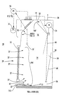
The
baffle assembly 60 is supported from wall left part 161 and right part 161'
brackets that are screw fastened to existing non asbestos lined fume hoods and
preferably with chemical resistant epoxy adhesive for asbestos lined fume
hoods.
The top articulating baffle assembly 66 is comprised of a series of
interconnected
parts 163, 164, 165, 169 and 170 connected preferably by machine screws as
shown. The assembly preferably has a lift out feature for ease of cleaning
baffle
conduit of trapped debris. The top baffle assembly 66 is supported on a
telescoping square rod assembly 162 and 168, with an actuator drive clevis
bracket 179, the lower articulating baffle 68 is assembled from parts 172 and
173.
The lower articulating baffle assembly 68 is interconnected to top baffle with
tabs
(not shown) inserted into top baffle assembly 66 and supported by rod 171. The
lower baffle assembly 68 increases lower baffle corner slot exhaust airflow by
tapering angle 175 by calculating E Re FIG. 8 from about the midpoint of the
lower baffle sides 172 and 173 to the bottom support. The increased lower
baffle
corner slot exhaust reduces the otherwise increased corner static pressure
losses
within the baffle conduit.
[0125] The baffle assembly accommodates a 47" internal height prior art hood.
Optional extension 174 is added to the lower baffle for conversion of hoods
with
internal heights greater than about 47"; the gap between work surface and
lower
baffle exhaust slot opening is 3".
CA 02632195 2008-05-13
WO 2007/047367 PCT/US2006/039890
[0126] FIG. 15A and 15B illustrate two views of one embodiment of a vortex
chamber turning vane 95 kit required for control sequence FIG. 9. The vortex
chamber turning vane 95 is comprised of an upper panel 192 connected to a top
edge 191 that is preferably angled downward from the upper panel. The upper
panel 192 is supported by a left bracket 193 and a right bracket 193' that
fasten to
existing asbestos liners preferably using chemical resistant epoxy and non
asbestos liners with screws, with angle determined by calculating ERe FIG. 8.
Top edge 191 is adjustable so that it can seal the vortex chamber turning vane
95
to existing fume hood ceilings. Incorporated within the upper panel 192 is a
Plexiglas panel 194, which is removable for servicing hood lights. An
adjustable,
expandable lower panel 196 is connected to the upper panel 192 by way of an
intermediate panel 195 that interlocks by tabs that also serves as an
adjustable
hinge to the upper panel 192 and the lower expandable sliding panels 195 and
196
and secured by mechanical screw connecting means. Panel 196 lower edge is
supported by 197 and seals sash 18 (not shown). When installed in accordance
with FIG. 9, the vortex chamber turning vane 95 closes the area between the
sash
18 and the vortex chamber 16.
[0127] FIG. 16A and 16B illustrate two views of an embodiment of a vortex
chamber turning vane 95 kit required for control sequence FIG. 10 and FIG. 11.
The kit is similar to that of the kit for control sequence 13 (FIG. 15A) with
some
changes. Top edge 191 of upper panel 192 is adjusted to achieve vortex bypass
airflow (VBA) as calculated in step No. 10. Additional parts 198 and 199 are
included to create the VBA bypass conduit, which allows air to circumvent the
vortex chamber 16. Panel 198 is secured to the top front edge of enclosure 12
using chemical resistant epoxy for asbestos lined fume hoods and screws on non
asbestos lined fume hoods and the lower edge is supported on 197. Part 199
supports lower edge of panel 196 which forms the bypass conduit with part 198.
Control sequence FIG. 11 vortex chamber turning vane does not use brackets 193
and 193' as the upper panel 192 is hinged and cannot be fixed into place by
these
brackets, which position is preferably actuator controlled by a vortex total
pressure controller (not shown).
[0128] FIG. 17 illustrates one embodiment of a kit to field convert an
existing
prior art vertical or combination vertical horizontal sash into a triple track
CA 02632195 2008-05-13
WO 2007/047367 PCT/US2006/039890
26
horizontal sash 180 with tear drop sash handle 100 and combination bypass
diffuser and dynamic turning vane bypass airfoil (BDTVA) 115. The upper roller
track 120 sash frame is shorter in width than the existing hood opening. Post
spacer panels 126 fill gaps to eliminate existing sash channel turbulence. New
post airfoils 128 are attached to the spacer panels 126. Airfoils 128 reject
existing
turbulence created by picture window and utility valve handles in many
existing
hoods. The existing combination vertical/horizontal hood sash being converted
can either be removed and or modified or replaced, or lifted and abandon in
place
if converted to a horizontal sash. A deflector 122 is installed over triple
track
horizontal sash 180 to reject unwanted down flow air currents from supply make
up air ceiling diffusers.
[0129] If the existing counter balance weight system is fully functional, then
the
existing fume hood vertical sash is replaced using conversion upper roller
track
120 sash frame and horizontal triple track as described in FIG. 18. The
existing
counter weight system may be reused or a new counterweight system added as a
part of new window frame system. Post airfoils 128 are attached to existing
posts.
Combination work surface bypass diffuser and dynamic turning vane (BDTVA)
115 replaces existing airfoil and is secured to the hood by brackets and
screws
116. BDTVA airfoil 115 is located out of the fume chamber and beneath the sash
handle instead of inside the hood. This location contributes to the stable
vortex
conversion hood being safer and energy efficient, and also prevents Bunsen
burner
flame outs and allows for sensitive powder measurements requiring a triple
beam
electronic scale.
[0130] FIG. 18A and 18C illustrate two views of a preferred horizontal sash
panel
110 for use with the triple track horizontal sash conversion or with newly
constructed hoods. The sash panel 110 is preferably constructed of
polycarbonate
unless the chemical use requires a different panel material. Sash panel edges
are
protected by edge guards 111. Top roller guides 137 are secured to the sash
panel
110 by way of posts 135 connected to a sash extension 133 that is secured to
the
sash panel at about position 138, as illustrated in more detail in FIG. 18B. A
single tab bottom guide 109 is generally used, except two tabs are required on
radioactive hoods with leaded sash panels 110.
CA 02632195 2008-05-13
WO 2007/047367 PCT/US2006/039890
27
Exhaust Damper Assembly
[0131] An apparatus and method of replacing existing exhaust duct airflow
controls with a simple hard balance constant exhaust airflow communication
system is also provided. Prior art fume hood exhaust connections are typically
round with a sharp edge facing airflow. The baffle conduit varies from 2 1/2"
to 3"
deep by the internal width and height of the prior art fume hood. The aspect
ratio
of a conduit or plenum is the relationship of the depth versus the width. One
aspect of the invention is based on the discovery that this relationship
should not
be less than 0.25. On prior art fume hoods, however, the baffle aspect ratio
is
typically 0.0625 or less. This ratio creates high exhaust airflow in the
center baffle
exhaust slots with low or no exhaust slot airflow on the left and right sides
and the
lower corners of the hood. FIG. 19 illustrates prior art fume hood uneven
velocity
profile of the rear baffle conduit, where the arrows represent airflow.
[0132] To maximize the performance of prior art fume hood conversion into a
high performance low airflow fume hood preferably includes a bellmouth inlet
assembly 200 as illustrated in FIG. 20. The assembly 200 includes a bellmouth
exhaust nozzle 205 and preferably an airflow meter 207 to measure required FHE
and a linear trim damper 209 that equalizes the airflow velocity and static
pressure
across the baffle conduit and is adjusted for required FHE. The distance
between
the axis 211 of the linear trim damper 209 and the leading edge 206 of the
bellmouth exhaust nozzle 205 is preferably not more than 18 inches. The linear
exhaust damper axis 211 is positioned to point out towards the fume hood face.
The assembly 200 is inserted into the existing exhaust discharge connection
215
from the inside of the hood.
[0133] FIG. 21 illustrates a cross section of the bellmouth exhaust nozzle
neck
connection 205. The diameter D is sized to achieve FHE cfin (step no.4) at
1200
to 1300 FPM duct velocity. The diameter D in square feet area can be easily
solved by dividing FHE by 1250 FPM and selecting the closest size bellmouth in
accordance with Table 2 that equals the calculated value in square feet in
accordance with the following table.
FHE/1250 FPM = Area of bellmouth in Sq. feet
CA 02632195 2008-05-13
WO 2007/047367 PCT/US2006/039890
28
Table 2
(Area Sq.Ft)
4 (0.087) 9" 1 1/2" 1 1/2
(0.136) 10" 2 1/2 1 1/2
6 (0197) 12" 37, 2"
7 (0267) 13" 3" 2"
8 (0349) 14" 3" 2"
9 (0442) 15" 3" 2"
(0.545) 16" 3" 2"
11 (a660) 19" 4" 3"
12 (0.785) 20" 4" 3"
[0134] The linear trim damper 209 style, size and location creates the
conditions
to produce the velocity airflow pattern that overcomes up stream duct
configuration patterns and aspect ratio induced static pressure losses and low
airflow velocity on the left and right sides, and lower corners, of the
exhaust baffle
conduit. FIG. 22 illustrates the now induced uniform velocity profile across
the
bypass conduit by the incorporation of bellmouth inlet assembly 200 (not
shown)
and linear trim damper 209. The assembly 200 induces air flow velocity to
equalize across the baffle conduit to create a more uniform baffle exhaust
slot air
velocity across and thru the baffle conduit. The linear trim damper 209 will
be at a
60% to 70% opening at design FHE airflow when damper is sized at 1200 to 1300
FPM duct airflow velocity that will induce these desired effects at the
following
flow coefficient (Cv) at 65% opening.
Table 3
Valve Size Flow Coefficient Cv at FHE (step 4)
65% Open Exhaust CFM
6"0 630 200-250
8"0 1115 251-475
10"0 1790 476-725
12"0 2515 726-1000
[0135] Standard ventilation flat sheet metal style butterfly duct dampers have
quick opening trim, not linear trim. To achieve linear airflow
characteristics, teeth
A-D are preferably proportionally sized according to FIG. 23D and 23E and are
preferably positioned according to FIG. 23C on the leading edges FIG. 23A and
23B of the rotating disc 220. The teeth protrude into the air stream FIG. 23B,
CA 02632195 2008-05-13
WO 2007/047367 PCT/US2006/039890
29
creating linear airflow characteristics to damper opening that also reduce
static
pressure losses and noise. The teeth can be substituted with a proportionally
sized
1/2" perforated plate which still produces a linear airflow but with an
increase in
static pressure losses and noise. FIG. 23A illustrates the front view and FIG.
23B
the side view of the preferred damper design, which shows an actuator 230. The
damper 209 can have either a metal seat as shown or bubble tight rubber seal.
There are no size limitations to the design except the teeth become
proportionally
bigger as the damper size changes. A swing-through round disc with 90 degree
rotational design is required for dampers smaller than 6" in diameter. Larger
dampers will be trunnion style with elliptical shape disc with 60 degrees of
rotation.
[0136] Unlike prior art fume hoods based on face velocity, fume hood
conversion
to a high performance low airflow hood is based on a precise airflow control
achieved by calculating FHE using ERe as described above. Using prior arts
method of multiple face velocity measurement of the sash opening to determine
fume hood exhaust airflow is imprecise. For one reason, the person taking the
measurements can greatly influence the results. For accurate fume hood FHE
measurement, an airflow meter and airflow pitot meter probe is used. It is
located
between the leading edge 206 of the bellmouth exhaust nozzle 205 and linear
trim
damper 209 and transverses the airflow velocity profile. In one embodiment,
the
flow pitot meter probe having an upstream tube and a downstream tube that
transverse the airflow assembly as disclosed in patent 4,959,990 is used in
the
preferred embodiment. The pressure transducer for flow measurement is located
in the bore of a housing connecting the total pressure and static pressure
tubes and
by incorporating the differential pressure transducer into a valve that can
block
flow between the tubes airflow meter can be used for either remote or local
airflow communication monitoring system. The differential pressure transducer
and flow pitot meter can also be calibrated both locally and remotely. The
airflow
pitot probe can be used with the pressure transducer for other sequences.
[0137] Sequence FIG. 24A illustrates a commissioning and balancing FHE
communication system which can be accomplished either locally or remotely.
The damper 209 can be adjusted manually by reading desired airflow from pitot
meter flow element FE-1 on airflow indicator Fl-1 and manually adjusting
linear
CA 02632195 2008-05-13
WO 2007/047367 PCT/US2006/039890
fume hood exhaust damper FV-2 or remotely by automatically scanning pitot
meter flow element FE-1 pitot signal through commercially available multiple
pressure selecting Scanivalve system thru differential pressure transducer PT-
2
and sequencing computer FI-2 and HC-2 controlling actuator M-2 on linear
damper FV-2 to obtain desired airflow.
10138] FIG. 24B illustrates an automatic communication sequencing balancing
and commissioning FHE system utilizing the combined differential pressure
transducer/pitot tube airflow meter FE-3/FT-3 with remote auto zero and span
calibration thru computer FY-3 and Scanivalve system FTV with differential
pressure transducer PT-3 and probe actuator M-3. Computer function HC-4
automatically adjusts for required FHE airflow by manipulating linear damper
FV-4 thru actuator M-4 through computer HC-4.