Note: Descriptions are shown in the official language in which they were submitted.
CA 02632371 2008-05-28
~ ' .
ADJUSTABLE HEADER ASSEMBLY FOR SIGNAGE
The present invention relates in general to signage that might be used in a
"big box"
retail outlet, such as one of the home improvement variety, and in particular
to a header
assembly for removable/replaceable signs or graphics.
BACKGROUND OF THE INVENTION
Retail outlets are replete with signs, advertising products and/or special
sales and
providing information to customers and staff alike. Signs can be of any size,
shape and/or
color; they can be purely graphical in nature, showing pictures, sketches
and/or
pictographs; they can be purely textual in nature; they can be a combination
of text and
graphics; they can be permanently or temporarily mounted to a shelf or other
support; or
they can be free-standing. When the retail outlet is large in area and volume,
such as a so-
called "big box store", small signs can become almost invisible to the
customers and staff.
Signs in such stores tend to be large in size (area) and they tend to be
secured to some
form of support, such as a shelf. Most such signs are fixed in position by
suitable means.
They usually cannot be positionally adjusted, whether to provide access to
goods stored on
the shelf behind the sign, or to provide ready access to the sign so that the
informational
portion thereof can be changed or updated.
SUMMARY OF THE INVENTION
The present invention meets the needs expressed above for a sign that is
adjustable
in its position so as to provide access to goods stored behind it, and to
provide access to the
sign so that it can be changed or updated as desired. The preferred embodiment
of the
invention provides a header frame assembly that carries means for supporting
the sign to
be held by the header frame. The apparatus of the invention also includes
support brackets
that can be removably connected or mounted to appropriate shelf structure. The
header
frame is preferably generally rectilinear in configuration, with parallel
upper and lower frame
members separated and interconnected by at least generally vertical end frame
members.
An arm extending upwardly and rearwardly from the frame assembly at each end
thereof
carries a rotatable wheel on a pin, which pin is receivable in a vertically
extending slot of an
associated bracket. Each slot leads into an upper portion which extends
upwardly and
rearwardly of the bracket. The slot also leads into a lower labyrinthine
portion which
1
CA 02632371 2008-05-28
provides an S-shaped path for a laterally extending pin at the lower end of
the frame
assembly. The labyrinthine portion also includes a notch for reception of the
pin, such that
with the pin engaged in the notch the frame assembly is fixed in a raised
condition, making
the signage fully visible and the shelf behind the signage inaccessible. When
the pins are
disengaged from their associated notches, the signage can be lowered to
provide access to
the shelf and to facilitate any desired change to the signage.
In its broadest form, the present invention may be considered as providing an
adjustable header assembly for the mounting of signage to a support,
comprising: frame
means including clip means adapted to carry such signage thereon; bracket
means
removably mountable to such support; guiding means associated with such
bracket means
and such frame means for guiding the frame means in a vertically oriented
direction; and
fixing means associated with such bracket means and such frame means for
fixing the
frame means in at least one of two vertically oriented positions, an upper
position blocking
access to the support surface and a lower position providing access to the
support surface.
In its preferred form, the present invention provides an adjustable header
assembly
for mounting signage to a support comprising: a generally rectilinear frame
assembly
including parallel upper and lower frame members interconnected by generally
vertically
extending end frame members; means associated with the frame assembly adapted
to
engage with peripheral areas of the signage so as to support such signage on
the frame
assembly; guide wheel means carried at each end of the frame assembly on an
associated
arm extending rearwardly and upwardly of the frame assembly; a pair of
brackets adapted
for spaced apart mounting to the support, each bracket including slot means
extending at
least vertically thereof, the slot means including lower portions defining
locking means for
the frame assembly and being adapted for guiding interaction with the guide
wheel means;
and pin means extending outwardly from each vertically extending end frame
member
adjacent a lower end thereof, the pin means being engageable with the locking
means of an
adjacent bracket to lock the frame assembly in a raised condition thereof.
In a second iteration, the present invention provides an adjustable header
assembly
for mounting signage to a support member, comprising: a generally rectilinear
frame
assembly including parallel upper and lower frame members interconnected by
generally
vertically extending end frame members, at least the upper frame member
defining a
channel opening to the rear of the frame member; clip means carried by the
upper and
lower frame members and adapted to engage with peripheral areas of the signage
so as to
2
CA 02632371 2008-05-28
support such signage on the frame assembly; a pair of support brackets each
adapted to be
mounted to the support member, each such support bracket including flange
means for
securement to the support member, a first leg to which the flange means is
connected, a
second leg extending normal to the first leg and defining a support surface
for the frame
assembly, and a pivot leg extending normal to the second leg and parallel to
the first leg; a
pair of first elongated pivot arms, each such arm being pivotally connected at
a proximal
end thereof to the pivot leg of a respective support bracket and rotatably
mounting a roller
wheel at the distal end thereof, each roller wheel being receivable within the
channel of the
upper frame member; and a pair of second elongated pivot arms, each such
second pivot
arm being pivotally connected at a distal end thereof to a respective first
pivot arm
intermediate the proximal and distal ends thereof, and being pivotally
connected at a distal
end thereof to the upper frame member between a respective end of the upper
frame
member and the roller wheel of the first pivot arm to which the second pivot
arm is
connected.
In yet another embodiment, the present invention provides an adjustable header
assembly for mounting a sign to a support comprising: upper and lower
horizontally
extending clip members for co-operating with upper and lower edges,
respectively, of the
sign to be carried by the header assembly; a pair of spaced apart track
members extending
perpendicular to the clip members and secured thereto, the track members
opening to a
rear of the assembly; a pair of clamping members, each slidably received in a
respective
one of the track members and adapted for being removably clamped to the
support; a
locking member adapted for being removably clamped to the support between the
track
members; and a locking mechanism mounted between and to the track members
adjacent a
lower end thereof, the locking mechanism including pivotable locking means
engageable
with the locking member when the header assembly is in a first raised position
relative to
the support and separable from the locking member to permit the header
assembly to be
lowered to a second lowered position.
BRIEF DESCRIPTION OF THE DRAWINGS
Figure 1 is perspective view of a first embodiment of the present invention in
a
raised condition and in position on a shelf of a retail establishment.
Figure 2 is an enlarged end view of the upper frame member of the present
invention.
3
CA 02632371 2008-05-28
Figure 3 is a perspective view of one of the support brackets of the present
invention.
Figure 4 is an enlarged perspective view showing a portion of the upper frame
member and the relative positioning of the first and second arms therein.
Figure 5 is a perspective view of the present invention in a lowered
condition.
Figure 6 is an illustration of signage according to a second embodiment of the
present invention in position on a shelf of a retail establishment.
Figure 7 is a rear view of the signage support of the second embodiment.
Figure 7a is a rear perspective view of the signage support of the second
embodiment.
Figure 8 is an enlarged view of the locking mechanism used with the signage
support
of the second embodiment.
Figure 9 is a perspective view of the locking mechanism.
Figure 10 is a partial perspective view of the clamping mechanism used with
the
signage support of the second embodiment.
Figure 10a is another partial perspective view of the clamping mechanism of
Figure
10.
Figure 11 is a partial perspective view showing a locking pin used with the
locking
mechanism of the second embodiment.
Figure 12 is a view showing the interior of the lock box of the locking
mechanism.
Figures 13a, 13b and 13c show the present invention mounting signage of
different
peripheral shapes.
Figure 14 is a schematic representation of a third embodiment of the present
invention, shown in a lowered condition.
Figure 15 is a schematic representation of the third embodiment, shown in a
raised
condition prior to locking in place.
Figure 16 is a partial enlarged side view showing the relative positions of
the
components in the raised condition of the signage.
Figure 17 is a partial side view showing a guide wheel of the third
embodiment.
Figure 18 is a side view of one of the brackets used with the third
embodiment.
Figure 19 is a cross-sectional view on the line 19-19 of Figure 18.
4
CA 02632371 2008-05-28
DESCRIPTION OF THE PREFERRED EMBODIMENTS
Figure 1 is a perspective view showing a first embodiment of a header assembly
10
according to the present invention as it would be seen in use, mounted to a
shelf 12 of a
retail outlet, such as a "big box store". The header assembly is shown without
specific
signage in place thereon, it being understood that the signage per se forms no
part of the
present invention, save that the signage will have upper and lower edges that
will be
utilized for retention purposes. Reference may be made to Figure 6 to see
signage in
position within a header assembly, Figure 6 pertaining to the second
embodiment of the
present invention.
The header assembly 10 comprises a generally rectilinear frame assembly 14
made
up of generally horizontal parallel upper and lower frame members 16, 18
interconnected
and held in position by generally vertical end frame members 20, 22. For
additional rigidity,
one or two central vertical support members 24 can be provided as well.
At least the upper frame member 16 is formed from an extruded channel-shaped
length of suitable material such as steel, aluminum or plastic. As seen in
Figure 2 this
frame member has a generally square, open, cross-section, with the channel 26
thereof
being defined by the upper 28 and lower 30 legs of the member, connected
together by the
inner bight portion 32. Upper 34 and lower 36 reentrant flanges complete the
channel,
there being a gap 38 between the facing edges of the flanges 34, 36. The lower
frame
member 18 may be a closed box section or it also may be formed as a channel
member, the
same as the upper frame member 16.
The channel 26 faces or opens to the rear of the header assembly 10. Each of
the
frame members 16, 18 carries an extruded clip member 40 that is adapted to
engage a
corresponding edge of the signage to be carried by the header assembly, the
upper and
lower clip members being the same but oriented in opposite directions. As can
be seen
from Figure 2 the upper clip member 40 has a main channel portion 42 that
clips onto the
upper frame member 16 and a pair of flanges 44, 46 extending downwardly from a
forwardly projecting flange member 48. The flange 44 defines a first channel
50 between
itself and the body of the clip member 40 while the flange 46 defines a second
channel 52
between itself and the flange 44. When the header assembly is in use upper and
lower
channels 50 will be vertically aligned with each other as will upper and lower
channels 52.
The signage can be positioned within either of the aligned pairs of channels
for ready
viewing by customers of the store. It would also be possible to arrange a
plurality of signs
CA 02632371 2008-05-28
within the aligned channels so as to impart a plurality of messages to the
customers of the
store.
Figure 3 shows a perspective view of one of the support brackets 54 that is
part of
the header assembly of the present invention and which is used to support the
header
frame on a shelf or other similar structure. Preferably, a pair of support
brackets 54 will be
utilized with the present invention, only one being described herein. It will
be noted that
the support bracket 54 shown in Figure 3 includes an upper flange 56 that is
adapted to rest
on the upper surface of the shelf so as to bear the weight of the header
assembly. The
flange 56 can be provided with a through aperture 58 permitting the flange to
be solidly
secured to the shelf by a suitable fastener (not shown) such as a lag bolt.
Alternatively, a
second flange 60, shown in broken lines, can be provided below the flange 56,
with the
second flange carrying a rotatable threaded rod 62 and a clamp member 64.
Using the
clamp member 64 will permit the support bracket to be readily removed from the
shelf so
that it can be used elsewhere without damaging the shelf. Of course, a
combination of
clamp and fastener can be utilized to provide even greater strength to the
attachment of the
support bracket to shelf.
The flange 56 (and the flange 60 if provided) extends rearwardly from a
generally
vertically oriented leg 66, from which projects forwardly a lower support leg
68 engageable
with the lower edge of the lower frame member 20. Furthermore, an upright leg
70
projects upwardly from the lower leg 68 close to but spaced from the leg 66 of
the support
means.
Each of the support brackets 56 has a first elongate pivot arm 72 pivotally
connected
at a proximal end thereof to, preferably, the vertically oriented leg 66. The
opposite, or
distal, end of the first pivot arm 72 carries a roller wheel 74 rotatably
mounted on a pivot
pin or axle 76. The roller wheel 74 is sized for rolling reception within the
channel 26 of the
upper frame member 16, the wheel being retained therein by the reentrant
flanges 34, 36
with the pivot axle extending therebetween through the gap 38. The roller
wheel 74 can be
introduced into the channel 26 through the adjacent open end of the frame
member 16.
A second pivot arm 78 is provided for each end of the header assembly, each
pivot
arm 78 being pivotally connected, at a proximal end thereof, to the first
pivot arm 72
intermediate the proximal and distal ends of the arm 72. At the distal end
thereof each
second pivot arm is pivotally connected, as by pivot pin 79, to the upper
frame member 16
between the adjacent end of the frame member and the roller wheel 74 carried
by the first
6
CA 02632371 2008-05-28
pivot arm 72.
A removable stop member 80 is secured to the upper frame member 16
intermediate
the connection thereto of the second pivot arm 78 and the roller wheel of the
first pivot arm
72. The stop member prevents the roller wheel 74 from moving too far along the
channel
during vertical movement of the header assembly.
The orientation and relative positioning of the first and second arms 72 and
78, the
stop member 80, and the channel 26 is seen in Figure 4.
The operation of the header assembly of the present invention will now be
described,
with particular reference to Figures 1 and 5. Figure 1 shows the header
assembly in its
raised position, with the lower frame member 18 supported by the lower legs 68
of the two
support brackets 56. It should be noted that, if desired, and in particular if
the frame
assembly 14 is large, there could be utilized several additional support
brackets
intermediate the end brackets. Of course, if intermediate brackets are used
then there
would be no pivot arms connected thereto. In the position shown in Figure 1
the first and
second pivot arms 72 and 78 form a y" shape, with the roller wheel 74 of each
first pivot
arm being at its outermost location, farthest away from the center of the
upper frame
member 16.
When it is desired to change the signage carried by the frame assembly 14 or
when
it is necessary to gain access to the shelf area behind the frame assembly one
will first of all
lift the frame assembly so that the lower frame member 18 can clear the
upwardly
extending lip 82 provided at the outer end of the lower leg 68 of each support
bracket 56.
The lower frame member 18 is then moved outwardly away from the shelf and the
support
brackets so that the entire frame assembly 14 can be lowered relative to the
shelf. There is
sufficient play in the components of the header assembly to permit such
movement. The
outward movement is depicted by the arrow A. Then the frame assembly 14 is
lowered in
the direction of the arrow B until the upper frame member 16 can be supported
by the
outwardly projecting legs 68 of the support brackets 56. The frame assembly 14
is
maintained parallel to the shelf and its downward motion is controlled by the
pairs of first
and second pivot arms 72, 78. During the downward movement each second pivot
arm
pivots about its distal connection to the upper frame member 16 while the
roller wheel 74 at
the distal end of the first pivot arm moves laterally within the channel 26
towards the center
of the frame member 16. The lowered position of the frame assembly is
illustrated in Figure
5. In its supported lowered position it is possible for an operator to remove
the existing
7
CA 02632371 2008-05-28
signage carried by the header assembly and to replace that signage with new
signage
imparting new information to potential customers. Furthermore, full access to
the shelf to
which the header assembly is mounted, is now available inasmuch as the header
assembly
is fully clear of the shelf and there is no impediment to such access.
Figure 6 illustrates a second embodiment of the present invention wherein a
sliding
header assembly 100 displays the actual informational sign 112 held in a
generally
rectangular support or header frame 114. The sliding header assembly carries
the sign 112
so that it is directed toward potential customers who might be interested in
the information
imparted by the sign itself. The sign 112 can be completely textual,
completely graphical,
or a combination of text and graphics. The nature of the sign 112 and the
information
imparted thereby is immaterial as far as the invention is concerned. The
header assembly
100 is shown as being positioned at the forward edge of a shelf 116 carrying
goods,
presumably for sale or in temporary storage, thereon.
Figure 7 shows the rear of the support or header frame 114. There it is seen
that
the header frame 114 may include a backing plate 118, generally rectangular in
configuration, with a pair of sign-engaging clips 120, 122 extending along the
upper and
lower edges of the plate 118. The clips 120, 122 are adapted to engage the
upper and
lower edges, respectively, of the sign 112. The clips 120, 122 can extend
forwardly of the
backing plate 118 so that when the sign is positioned in the header 114 it
will take on a
concave appearance as seen in Figure 6. If the upper clip 120 extends
forwardly a distance
greater than that by which the lower clip 122 extends then the sign 112 will
take an attitude
that is angled relative to the backing plate 118. If, for example, the header
is secured so as
to be vertical, then the sign would be angled downwardly towards the floor of
the retail
outlet, making the information thereon more readily visible to someone
endeavoring to read
the sign 112. The clips 120, 122 can come in a variety of configurations and
are generally
as disclosed and discussed in commonly owned US Patent Application No.
11/206,270 of
August 18, 2005 (published as US 2006/0070285 on April 6, 2006. A pair of end
plates
124, 126 cap off the header frame at the respective ends thereof, extending
between and
attached to the clips 120, 122. The end plates 124, 126 will prevent the sign
112 from
sliding lengthwise out of the header 114.
Extending between the clips 120 and 122, generally symmetrical to a central
vertical
centerline of the header 114 is a pair of U-shaped channels or track members
128, 130.
The track members are spaced apart by a suitable distance. Each track member
includes a
8
CA 02632371 2008-05-28
bight or rear wall 132, a pair of side walls 134, 134 extending
perpendicularly to the rear
wall, and a pair of reentrant flanges 136, 136 extending towards each other
from the free
edge of the respective side walls 134, 134. The free edges of the flanges 136,
136 are
spaced from each other, providing by a gap therebetween access to the interior
of each
track member as defined by the walls and flanges thereof.
The track members 128, 130 are securely connected to the respective upper and
lower clips 120, 122 as by way of nuts and bolts, by spot welding, by a
suitable adhesive,
by rivets, by machine screws, or by any other suitable fastening means. Since
the track
members act to space the clips 120, 122 apart it is possible that the header
frame 114 can
be manufactured without a backing plate 118, with the clips 120, 122, the end
plates 124,
126 and the track members 128, 130 creating a skeletal frame that is
sufficiently rigid to
effectively carry the sign 112, without the need for a backing plate. A
backing plate will, of
course, increase the rigidity of the header assembly 100, although it would
also increase the
weight thereof.
Each track member carries a clamping mechanism 138 best seen in Figures 10 and
10a. Each clamping mechanism includes a base or support member 140 with a
depending
clip member 142 that has a sliding fit within the interior of the track
member, co-operating
with the walls and flanges thereof to permit movement of the clip member along
the track
member while retaining the clip member 142 so that it cannot exit the track
member except
at an open end thereof. The base member 140 mounts thereon a C-shaped clamp
144, the
clamp 144 including a threaded member 146 with a foot member 148 thereon. The
threaded member 146 can be rotated so as to clamp a shelf or a portion thereof
between
the foot member 148 and the base 150 of the clamp, to thereby secure the
header 114 to a
shelf or any other suitable member. While the clamp 144 is illustrated in an
orientation
such that the structure (for example the front lip of a shelf) to which the
clamp would be
secured extends vertically, parallel to the track members 128, 130, it is
clear that the clamp
144 could be oriented such that it could be secured to a horizontally
extending structure,
such as a shelf itself.
With reference to Figures 11 and 11a a C- or U-shaped mounting member 152 is
provided for clamping directly to a shelf 116 or to a vertical flange 154 of
the shelf. The
member 152 is preferably in the form of a clamp that can be removably secured
to the shelf
or flange by way of a suitable clamping member (not shown). The clamping
effect has to be
sufficiently strong to support the weight of the header assembly 100. A pin
member 156 is
9
CA 02632371 2008-05-28
affixed to one of the walls of the member 154 and extends or projects away
from the
member 154 so as to be parallel to the side walls 134 of the track members
128, 130.
With reference to Figures 7, 7a, 8, 9 and 12 it will be noted that the
structure of the
header frame 114 includes a locking mechanism 160 that is secured to a pair of
mounting
bars 162, 162 that extend laterally between the track members 128, 130
adjacent the lower
edge of the header 114. The locking mechanism includes a pair of opposed
plates 164, 164
(only one is seen in the drawings), an opening 166, a locking arm 168 which
intrudes into
the opening 166, a release tab 170 and a locking tab 172. The interior of the
locking
mechanism 160 is best seen in Figure 12, where the locking arm 168 is
pivotally secured to
one of the opposed plates 164 by way of a pivot pin 174. The locking arm 168
includes a
first portion 175 which co-operates with the pivot pin 174 and an arcuate
second portion
176 which defines, with the first portion 174, a C-shaped opening 178 sized to
closely fit on
the locking pin member 154. The locking arm 168 extends from the first and
second
portions to a leg portion 180 from which a pin member 182 extends and is
slidably received
within an elongated slot 184 of a plunge arm 186. The plunge arm 186 is
pivotally mounted
to the plate 164 by way of a pivot pin 188. A tension spring 190 is connected
to the plunge
arm 186 near the slot 184 as well as to the plate 164. At the opposite end
thereof the
plunge arm 186 is pivotally connected to one end 192 of the elongated lock
release tab 170
by pivot pin 194, the other end 196 of which is available to be pushed. The
lock release tab
170 is slidably confined within the locking mechanism 160 for vertical
movement as seen in
Figure 12.
In operation, the header frame 114 would first of all be positioned relative
to a shelf
116 and the clamping mechanisms 138 operated so as to clamp the to the shelf
or to a
flange or lip 154 thereof. The mounting member 152 is clamped to the shelf or
flange so
that the pin member 156 is vertically aligned with the opening 166 of the
locking
mechanism. With the header frame 114 in its lowermost position relative to the
clamping
mechanism 138 a sign 112 can be located within the confines of the header
frame, with the
upper and lower edges thereof engaging the respective upper and lower clip
members 120,
122. Then, the entire signage can be raised relative to the shelf 116 and the
clamping
mechanisms 138 by pushing upwardly on the locking tab 172 of the locking
mechanism
160. The push may be applied by hand or by any suitable instrument, including
for
example a broom handle. The header frame and the sign carried thereby are
raised relative
to the clamping mechanisms and the shelf until the second portion 176 of the
locking arm
CA 02632371 2008-05-28
168 contacts the locking pin member 156. Since the second portion 176 of the
locking arm
is curved as seen in Figure 12 it will be pivoted or cammed by the pin member
156 until the
free end passes the pin member and the pin member enters the C-shaped opening
178.
The locking arm will pivot back, under the influence of the tension spring, so
as to capture
the pin member in the opening 178, thereby locking the header 114 with respect
to the pin
member 178 and thus with respect to the clamping mechanisms and the shelf.
With the
locking mechanism in place the sign is prevented from descending to its
lowermost position.
When it is necessary to access the goods carried by the shelf 116 behind the
header
assembly 100, or when it is necessary to replace, for example, the sign 112
carried by the
header frame 114, it is possible to quickly and easily lower the signage from
its uppermost
position relative to the shelf to its lowermost position. This is accomplished
by pushing
upwardly on the available end 196 of the release tab 170 by hand or with any
suitable
implement, such as the aforementioned broom handle. Upward movement of the
release
tab 170 will impart an upward movement to the adjacent end of the plunge arm
186
causing the plunge arm to rotate on the pivot pin 188. The plunge arm 186, by
way of the
slot 184, will exert a downwards force on the pin member 182 of the locking
arm 168
causing it to rotate on the pivot pin 174. This in turn opens the C-shaped
opening vertically
such that the weight of the header assembly 100 will cause it to descend away
from the
locking pin member 156. The signage can then be lowered away from the locking
pin
member 156, the clamping mechanism 138 and the shelf 116. With the signage in
its
lowermost position assess to goods on the shelf 116 is enabled and the sign
112 can be
changed or adjusted as necessary.
Note that the upper end of each track member 128, 130 will carry a suitable
plug or
cap (not shown), secured to its track member to prevent the signage from
separating from
the clamping mechanisms during the descent thereof. The plugs or caps can be
removably
secured to the track members so that the clamping mechanisms can be removed
from the
track members for assembly or disassembly of the header.
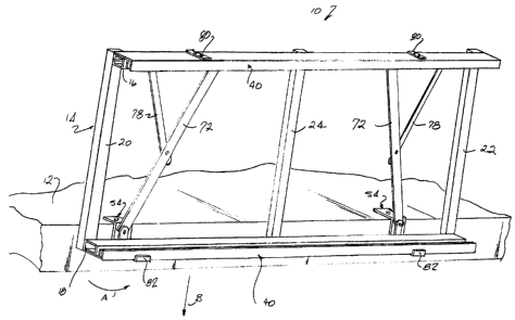
Figures 14 to 19 are illustrative of a third, and preferred, embodiment 150 of
the
present invention. In this case, the frame carrying appropriate signage is
designated by the
reference number 152, it being noted that the frame can be similar to the
frames depicted
in the first and second embodiments. The present description is primarily
concerned with
the mechanism for mounting the frame to a support and to the means for guiding
the frame
during raising and lowering thereof.
11
CA 02632371 2008-05-28
With reference to Figures 14 and 17 it will be seen that the frame 152 is
provided, at
each end thereof, with a vertically and rearwardly angled arm 154, the arm at
its proximal
end being affixed to the frame by any suitable means such as rivets, metal
screws, or bolts
and nuts. At its distal end each arm carries a rotatable guide wheel 156 on a
pin 158
affixed to the arm. The wheel 156 will be outboard of each arm.
Right and left mounting brackets 160, 162 are provided for mounting to,
preferably,
vertical supports of a shelving unit, by way of one or more of the through
holes 164. One of
the brackets is best seen in Figures 18 and 19. There it is seen that each
bracket has at
least three mounting holes 164 spaced apart along one vertical edge 166. The
mounting
holes 164 can be elongated so as to accommodate different spacings between
corresponding mounting holes in the associated vertical supports.
At it upper end, each bracket has a portion 168 that extends rearwardly of the
bracket. A guide slot 170 extends vertically adjacent the opposite edge 172
and leads into
an upper portion 174 that angles upwardly and rearwardly into the extension
portion 168.
At its lower end the slot leads into a labyrinthine portion which includes a
short portion 176
that slopes slightly upwardly and forwardly towards the vertical edge 166. A
short vertical
portion 178 extends upwardly from the free end of slot portion 176, leading to
another short
portion 180 that extends forwardly to and opens at the edge 172. As seen in
Figure 18, a
small notch 182 extends downwardly at the free end of short portion 176, as a
downward
extension of the vertical slot portion 178.
As can be seen in Figure 19, the outboard surface of each bracket is provided
with a
pair of opposing L-shaped flanges 184, 186 each of which has a short leg
portion 188
extending outwardly of the bracket, and a reentrant arm portion 190 which
faces the
opposing reentrant arm portion of the other flange. The width or distance
between the leg
portions 188 of the flanges is slightly greater than the outer diameter of the
guide wheel
156 carried by the adjacent arm 154 mounted to the frame 152.
Turning now to Figures 14 to 16, the operation of the third embodiment will
now be
described. Starting with the condition shown in Figure 14 it will be seen that
the frame 152
is lowered relative to the brackets 160, 162, the lowered condition providing
access to a
shelf or shelves normally blocked when the signage carried by the frame 152 is
in the raised
condition. In the lowered condition the guide wheels 156, contained by the
flanges 184,
186 are at the bottom of the vertical slot 170 and the frame is suspended
therebelow.
Access to the shelf or shelves is now possible, and the signage carried by the
frame can be
12
CA 02632371 2008-05-28
changed or altered as desired.
To move the signage to a raised condition, as seen in Figure 15, the frame has
been
moved vertically and the guide wheels 156 have moved upwardly in the channel
defined by
the flanges 184, 186, into the angled slot portions 174. During the upward
movement the
frame 152 has been angled forwardly, pivoting on the pins 158 to which the
wheels 156 are
mounted.
At the uppermost elevation of the frame 152, with the wheels 156 within the
angled
slot portions174, a pin 192 which extends outwardly from each side wall of the
frame 152 at
the lower end thereof, will be aligned with the entrance to each of the short
slot portions
180. Each pin 192 can then enter the adjacent slot portion 180, slide
therealong, and then
follow the vertical slot portion 178 downwardly until it rests in the notch
182. With the pins
resting in the notches the frame is locked or fixed in place, with the signage
carried by the
frame available to provide appropriate information to customers and others
desirous of
becoming informed by the material carried by the signage.
The present invention clearly enables staff of a store or other facility to
readily alter
and adjust signage intended to impart information to passers-by and it also
permits access
to a shelf or other structure to which the invention is mounted. While the
invention has
been described in relation to generally rectilinear signs, it need not be
restricted to such
signs; it would only be necessary to provide the generally rectangular frame
14, 114, 152
with suitable signage-carrying clip members 200, 202, 204 adapted to support
signs of a
different configuration (oval, circular, polygonal, e.g. hexagonal, et cetera)
as seen in
Figures 13a, 13b, and 13c. Such clip members would be secured to an
appropriate frame
206 of either the first or the second embodiment. Thus, while preferred
embodiments of the
present invention have been described herein the invention should not be
construed as
being restricted to such embodiments given that a skilled workman would be
able to effect
appropriate alterations to the invention without departing from the spirit
thereof.
13