Note: Descriptions are shown in the official language in which they were submitted.
CA 02632604 2013-08-23
METHOD FOR DISPLAYING CATHETER ELECTRODE-TISSUE CONTACT
IN ELECTRO-ANATOMIC MAPPING AND NAVIGATION SYSTEM
BACKGROUND OF THE INVENTION
a. Field of the Invention
[00021 The instant invention is directed toward an electrode catheter and a
method for
using the electrode catheter for tissue ablation. In particular, the electrode
catheter of the
present invention may comprise a circuit to assess electrode-tissue contact
and electrical
coupling for applying ablative energy (e.g., RF energy) to target tissue.
b. Background Art
100031 It is well known that benefits may be gained by forming lesions in
tissue if the
depth and location of the lesions being formed can be controlled. In
particular, it can be
desirable to elevate tissue temperature to around 50 C until lesions are
formed via
coagulation necrosis, which changes the electrical properties of the tissue.
For example,
lesions may be formed at specific locations in cardiac tissue via coagulation
necrosis to
lessen or eliminate undesirable atrial fibrillations.
10004] Several difficulties may be encountered, however, when attempting to
form
lesions at specific locations using some existing ablation electrodes. One
such difficulty
encountered with existing ablation electrodes is how to ensure adequate tissue
contact and
electrical coupling. Electrode-tissue contact is not readily determined using
conventional
techniques such as fluoroscopy. Instead, the physician determines electrode-
tissue contact
based on his/her experience using the electrode catheter. Such experience only
comes
with time, and may be quickly lost if the physician does not use the electrode
catheter on
a regular basis. In addition, when forming lesions in a heart, the beating of
the heart
1
CA 02632604 2008-06-04
WO 2007/067938
PCT/US2006/061711
further complicates matters, making it difficult to determine and maintain
sufficient
contact pressure between the electrode and the tissue for a sufficient length
of time to
form a desired lesion. If the contact between the electrode and the tissue
cannot be
properly maintained, a quality lesion is unlikely to be formed. Similarly,
information on
electrical coupling between the electrode and the target tissue is not readily
available a
priori to determine how much ablative energy may be absorbed in the tissue
during
ablation. Instead, the physician uses generalized pre-determined ablation
parameters, such
as power and duration, based on his/her experience to perform ablation
procedures with
the electrode catheter. Such experience may lead to deficiencies,
inefficiencies and
complications, such as inadequate lesion formation, premature high impedance
shut-off,
tissue chaffing, and thrombus formation.
BRIEF SUMMARY OF THE INVENTION
[0005] The present invention relates to providing an indication to the
physician, via the
navigation system, concerning the electrical coupling of an electrode, such as
an ablative
electrode or mapping electrode, with the patient. During an electrode catheter
procedure,
a physician uses the navigation system for monitoring electrode position. The
navigation
system may provide real-time visualization of electrode movements and position
in
relation to physiological structure of the patient.
[00061 It has been recognized that it is desirable to provide an indication
concerning
electrode coupling with minimal distraction to the physician. This is
particularly the case
where the system is used not only for initially establishing a desired
electrode position for
a procedure, but also for monitoring electrode procedure during the procedure.
This can
be accomplished, in accordance with the present invention, by providing an
indication via
a monitor of the navigation system. In this manner, the physician can receive
continuously or periodically (occasionally) updated electrode coupling
information during
a medical procedure while the physician's attention remains substantially
fully directed to
the medical procedure.
[0007] In accordance with one aspect of the present invention, a method and
apparatus
("utility") is provided that supplies an indication to the physician, via the
navigation
system, concerning the electrical coupling of an electrode. The utility
involves
establishing an electrical coupling monitoring system for evaluating a tissue
coupling
2
CA 02632604 2008-06-04
WO 2007/067938
PCT/US2006/061711
relationship. Any suitable monitoring system may be used in this regard,
including
systems based on impedance, phase angle, mechanical vibration or mechanical
deformation measurements. The monitoring system is operative to distinguish
between at
least two different electrode coupling levels (e.g., insufficient or
sufficient coupling for
the procedure at issue) and may distinguish between more than two electrode
coupling
levels (e.g., insufficient coupling, sufficient coupling and elevated
coupling). In one
implementation, the electrical coupling monitoring system employs a phase
angle
technology where different electrode coupling levels are associated with
different phase
angle ranges. The utility further involves operating said electrode coupling
assessment
system in connection with a medical procedure to identify a level of electrode
coupling.
For example, the assessment system may be operated prior to initiation of an
ablative or
mapping procedure to analyze electrode coupling. Additionally or
alternatively, the
assessment system may be operated continuously or periodically during a
medical
procedure to monitor electrode coupling. An output is then provided indicating
the
identified level of electrode coupling. In particular, the output is provided
via the
navigation system used by the physician in monitoring the electrode. For
example, the
color or other display parameter of a representation of the electrode may be
altered to
indicate the level of electrode coupling. Additionally or alternatively, a
waveform
reflecting values of electrode coupling versus time may be provided in
connection with a
display of the navigation system.
[00081 In accordance with a still further aspect of the present invention, an
electrode
catheter system is provided that allows for providing electrode coupling
information with
minimal distraction. An associated utility involves: an electrode adapted to
apply
electrical energy; a catheter for enabling the electrode to be remotely
operated by a
physician; guidance instrumentation for guiding the electrode relative to the
physiological
structure of a patient; and a processor for receiving signal information and
determining a
level of electrical coupling between the electrode and the patient. The
guidance
instrumentation includes at least a navigation system for use in monitoring a
position of
the electrode. The processor is further operative to control the navigation
system to
provide an indication of the level of electrode coupling. In this regard, the
processor can
distinguish between a least two different levels of electrode coupling. In one
implementation, the processor can distinguish between multiple levels of
electrode
3
CA 02632604 2013-08-23
coupling, including a level indicating elevated coupling that may be
associated with the
potential for penetrating tissue of interest. Such penetration may be desired
or undesired.
In either event, an indication of such elevated coupling can be useful to a
physician. The
various levels of electrode coupling may be determined by any suitable
technology. In
one implementation, the levels are distinguished based on a phase angle
analysis.
BRIEF DESCRIPTION OF THE DRAWINGS
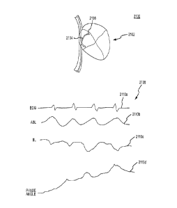
[0010] Fig. 1 is a diagrammatic illustration of an exemplary tissue ablation
system which
may be implemented to assess electrode-tissue contact during a tissue ablation
procedure
for a patient.
[0011] Fig. la is a detailed illustration of the patient's heart in Fig. 1,
showing the
electrode catheter after it has been moved into the patient's heart.
[0012] Fig. 2a illustrates exemplary levels of electrical contact or coupling
between the
electrode catheter and a target tissue.
[0013] Fig. 2b illustrates exemplary levels of mechanical contact or coupling
between the
electrode catheter and a target tissue.
[0014] Fig. 3 is a high-level functional block diagram showing the exemplary
tissue
ablation system of Fig. 1 in more detail.
[0015] Fig. 4 is a model of the electrode catheter in contact with (or coupled
to) target
tissue.
[0016] Fig. 4a is a simplified electrical circuit for the model shown in Fig.
4.
[0017] Fig. 5 is an exemplary phase detection circuit which may be implemented
in the
tissue ablation system for assessing electrode-tissue contact or coupling.
[0018] Fig. 6 is an exemplary block diagram showing phase angle measurement
for
contact sensing and tissue sensing.
[0019] Fig. 7 is an exemplary block diagram showing phase angle measurement
during
ablation with both ablation energy and a contact sensing signal applied to the
ablation
electrode at the same time.
4
CA 02632604 2008-06-04
WO 2007/067938
PCT/US2006/061711
[0020] Fig. 8 is an exemplary block diagram showing phase angle measurement
during
ablation with switching between a sensing signal and ablation power.
[0021] Fig. 9a illustrates one embodiment of a protocol that may be used to
assess a
coupling between an electrode and tissue based upon a phase angle comparison.
[0022] Fig. 9b illustrates one embodiment of a protocol that may be used to
assess a
coupling between an electrode and tissue based upon a reactance comparison.
[0023] Fig. 9c illustrates one embodiment of a protocol that may be used to
assess a
coupling between an electrode and tissue based upon an impedance components
ratio
comparison.
[0024] Fig. 10 illustrates a representative, schematic representation of an
electrical
coupling between an electrode and tissue.
[0025] Fig. 1 la illustrates a schematic of one embodiment of an ablation
system that uses
two power sources operating at different frequencies, where only one of these
power
sources is interconnected with the ablation electrode at any one time, and
where one of
these power sources is used for assessing a coupling between an electrode and
tissue.
[0026] Fig. 1 lb illustrates a schematic of one embodiment of an ablation
system that uses
two power sources operating at different frequencies, where both power sources
are
always interconnected with the ablation electrode, and where one of these
power sources
is used for assessing a coupling between an electrode and tissue.
[0027] Fig. 11c illustrates a schematic of one embodiment of an ablation
system that uses
two power sources operating at least generally at the same frequency, where
only one of
these power sources is interconnected with the ablation electrode at any one
time, and
where each of these power sources may be used for assessing a coupling between
an
electrode and tissue.
[0028] Fig. 12a illustrates one embodiment of a system for assessing a
coupling between
an electrode and tissue.
[0029] Fig. 12b illustrates one embodiment of a protocol that may be used to
assess a
coupling between an electrode and tissue based upon identifying a baseline
coupling
condition.
Fig. 12c illustrates one embodiment of a protocol that may be used to assess a
coupling
between an electrode and tissue based upon identifying a target frequency.
CA 02632604 2008-06-04
WO 2007/067938
PCT/US2006/061711
[0030] Fig. 13 is a schematic diagram of an electrode catheter system in
accordance with
the present invention.
[0031] Fig. 14 is a schematic diagram of an electrode coupling output system
in
accordance with the present invention.
[0032] Fig. 15 illustrates a handle set based electrode coupling output system
in
accordance with the present invention.
[0033] Fig. 16 illustrates a handle set incorporated various types of output
devices in
accordance with the present invention.
[0034] Fig. 17 illustrates a handle set incorporating a vibration device in
accordance with
the present invention.
[0035] Fig. 18 is a schematic diagram of a navigation system based electrode
coupling
output system in accordance with the present invention.
[0036] Figs. 19A-20D illustrate graphical representations of an electrode in a
navigation
system display in accordance with the present invention.
[0037] Fig. 21 illustrates a navigation system display in accordance with the
present
invention.
[0038] Fig. 22 is a flow chart illustrating a process for outputting electrode
coupling
information via guidance instrumentation in accordance with the present
invention.
DETAILED DESCRIPTION OF THE INVENTION
[0039] The present invention relates to providing an indication regarding a
condition of
interest, e.g., a level of electrode coupling, to a physician via guidance
instrumentation of
an electrode catheter system. While such an indication may be provided in
connection
with various parameters of interest in connection with an electrode catheter
procedure
and, specifically, in connection with a variety of electrode coupling
assessment
technologies, certain advantage are achieved by using an assessment technology
capable
6
CA 02632604 2008-06-04
WO 2007/067938 PCT/US2006/061711
of accurately identifying multiple electrode coupling levels such as a phase
angle
technology. In the following description, certain phase angle-related
technologies are
first described. Thereafter, various mechanisms for outputting information to
the
physician are described in detail.
[00401 Fig. 1 is a diagrammatic illustration of an exemplary electrode
catheter system 10
which may be implemented to assess electrode-tissue contact during a tissue
ablation
procedure for a patient 12. Catheter system 10 may include an electrode
catheter 14,
which may be inserted into the patient 12, e.g., for forming ablative lesions
inside the
patient's heart 16. During an exemplary ablation procedure, a user (e.g., the
patient's
physician or a technician) may insert the electrode catheter 14 into one of
the patient's
blood vessels 18, e.g., through the leg (as shown in Fig. 1) or the patient's
neck. The user,
guided by a real-time fluoroscopy imaging device (not shown), moves the
electrode
catheter 14 into the patient's heart 16 (as shown in more detail in Fig. la).
1
[0041] When the electrode catheter 14 reaches the patient's heart 16,
electrodes 20 at the
tip of the electrode catheter 14 may be implemented to electrically map the
myocardium
22 (i.e., muscular tissue in the heart wall) and locate a target tissue 24.
After locating the
target tissue 24, the user must move the electrode catheter 14 into contact
and electrically
couple the catheter electrode 14 with the target tissue 24 before applying
ablative energy
to form an ablative lesion or lesions. The electrode-tissue contact refers to
the condition
when the catheter electrode 14 physically touches the target tissue 24 thereby
causing a
mechanical coupling between the catheter electrode 14 and the target tissue
24. Electrical
coupling refers to the condition when a sufficient portion of electrical
energy passes from
the catheter electrode 14 to the target tissue 24 so as to allow efficient
lesion creation
during ablation. For target tissues with similar electrical and mechanical
properties,
electrical coupling includes mechanical contact. That is, mechanical contact
is a subset of
electrical coupling. Thus, the catheter electrode may be substantially
electrically coupled
with the target tissue without being in mechanical contact, but not vice-
versa. In other
words, if the catheter electrode is in mechanical contact, it is also
electrically coupled.
The range or sensitivity of electrical coupling, however, changes for tissues
with different
electrical properties. For example, the range of electrical coupling for
electrically
conductive myocardial tissue is different from the vessel walls. Likewise, the
range or
sensitivity of electrical coupling also changes for tissues with different
mechanical
7
CA 02632604 2008-06-04
WO 2007/067938
PCT/US2006/061711
properties, such as tissue compliance. For example, the range of electrical
coupling for
the relatively more compliant smooth atrial wall is different from the
relatively less
compliant pectinated myocardial tissue. The level of contact and electrical
coupling are
often critical to form sufficiently deep ablative lesions on the target tissue
24 without
damaging surrounding tissue in the heart 16. The catheter system 10 may be
implemented
to measure impedance at the electrode-tissue interface and assess the level of
contact
(illustrated by display 11) between the electrode catheter 14 and the target
tissue 24, as
described in more detail below.
[0042] Fig. 2a illustrates exemplary levels of electrical contact or coupling
between an
electrode catheter 14 and a target tissue 24. Fig. 2b illustrates exemplary
levels of
mechanical contact or coupling between an electrode catheter 14 and a target
tissue 24.
Exemplary levels of contact or coupling may include "little or no contact" as
illustrated
by contact condition 30a, "light to medium contact" as illustrated by contact
condition
30b, and "hard contact" as illustrated by contact condition 30c. In an
exemplary
embodiment, the catheter system 10 may be implemented to display or otherwise
output
the contact condition for the user, e.g., as illustrated by light arrays 3 la-
c corresponding
to contact conditions 30a-c, respectively.
[0043] Contact condition 30a ("little or no contact") may be experienced
before the
electrode catheter 14 comes into contact with the target tissue 24.
Insufficient contact may
inhibit or even prevent adequate lesions from being formed when the electrode
catheter
14 is operated to apply ablative energy. However, contact condition 30c ("hard
contact")
may result in the formation of lesions which are too deep (e.g., causing
perforations in the
myocardium 22) and/or the destruction of tissue surrounding the target tissue
24.
Accordingly, the user may desire contact condition 30b ("light to medium
contact").
[0044] It is noted that the exemplary contact or coupling conditions 30a-c in
Fig. 2a-b are
shown for purposes of illustration and are not intended to be limiting. Other
contact or
coupling conditions (e.g., finer granularity between contact conditions) may
also exist
and/or be desired by the user. The definition of such contact conditions may
depend at
least to some extent on operating conditions, such as, the type of target
tissue, desired
depth of the ablation lesion, and operating frequency of the RF radiation, to
name only a
few examples.
[0045] Fig. 3 is a high-level functional block diagram showing the catheter
system 10 in
more detail as it may be implemented to assess contact or coupling conditions
for the
8
CA 02632604 2008-06-04
WO 2007/067938
PCT/US2006/061711
electrode catheter 14. It is noted that some of the components typical of
conventional
tissue ablation systems are shown in simplified form and/or not shown at all
in Fig. 1 for
purposes of brevity. Such components may nevertheless also be provided as part
of, or for
use with the catheter system 10. For example, electrode catheter 14 may
include a handle
portion, a fluoroscopy imaging device, and/or various other controls, to name
only a few
examples. Such components are well understood in the medical devices arts and
therefore
further discussion herein is not necessary for a complete understanding of the
invention.
[0046] Exemplary catheter system 10 may include a generator 40, such as, e.g.,
a radio
frequency (RF) generator, and a measurement circuit 42 electrically connected
to the
electrode catheter 14 (as illustrated by wires 44 to the electrode catheter).
The electrode
catheter 14 may also be electrically grounded, e.g., through grounding patch
46 affixed to
the patient's arm or chest (as shown in Fig. 1).
[0047] Generator 40 may be operated to emit electrical energy (e.g., RF
current) near the
tip of the electrode catheter 14. It is noted that although the invention is
described herein
with reference to RF current, other types of electrical energy may also be
used for
assessing contact conditions.
[0048] In an exemplary embodiment, generator 40 emits a so-called "pinging"
(e.g., low)
frequency as the electrode catheter 14 approaches the target tissue 24. The
"pinging"
frequency may be emitted by the same electrode catheter that is used to apply
ablative
energy for lesion formation. Alternatively, a separate electrode catheter may
be used for
applying the "pinging" frequency. In such an embodiment, the separate
electrode may be
in close contact with (or affixed to) the electrode for applying ablative
energy so that a
contact or coupling condition can be determined for the electrode which will
be applying
the ablative energy.
[0049] The resulting impedance at the electrode-tissue interface may be
measured during
contact or coupling assessment (or "pinging") using a measurement circuit 42.
In an
exemplary embodiment, the measurement circuit 42 may be a conventionally
available
resistance-capacitance-inductance (RCL) meter. Another exemplary measurement
circuit
which may be implemented for determining the phase angle component is also
described
in more detail below with reference to Fig. 5. Still other measurement
circuits 42 may be
implemented and the invention is not limited to use with any particular type
or
configuration of measurement circuit.
9
CA 02632604 2008-06-04
WO 2007/067938
PCT/US2006/061711
[0050] The reactance and/or phase angle component of the impedance
measurements may
be used to determine a contact or coupling condition. The contact or coupling
condition
may then be conveyed to the user in real-time for achieving the desired level
of contact or
coupling for the ablation procedure. For example, the contact or coupling
condition may
be displayed for the user on a light array (e.g., as illustrated in Fig. 2a-
b).
[0051] After the user has successfully guided the electrode catheter 14 into
the desired
contact or coupling condition with the target tissue 24, a generator, such as
generator 40
or a second generator, may be operated to generate ablative (e.g., high
frequency) energy
for forming an ablative lesion or lesions on the target tissue 24. In an
exemplary
embodiment, the same generator 40 may be used to generate electrical energy at
various
frequencies both for the impedance measurements (e.g., "pinging" frequencies)
and for
forming the ablative lesion. In alternative embodiments, however, separate
generators or
generating units may also be implemented without departing from the scope of
the
invention.
[0052] In an exemplary embodiment, measurement circuit 42 may be operatively
associated with a processor 50 and memory 52 to analyze the measured
impedance. By
way of example, processor 50 may determine a reactance and/or phase angle
component
of the impedance measurement, and based on the reactance component and/or
phase
angle, the processor 50 may determine a corresponding contact or coupling
condition for
the electrode catheter 14. In an exemplary embodiment, contact or coupling
conditions
corresponding to various reactance and/or phase angles may be predetermined,
e.g.,
during testing for any of a wide range of tissue types and at various
frequencies. The
contact or coupling conditions may be stored in memory 52, e.g., as tables or
other
suitable data structures. The processor 50 may then access the tables in
memory 42 and
determine a contact or coupling condition corresponding to impedance
measurement
based on the reactance component and/or phase angle. The contact or coupling
condition
may be output for the user, e.g., at display device 54.
[0053] It is noted, that the catheter system 10 is not limited to use with
processor 50 and
memory 52. In other embodiments, analog circuitry may be implemented for
assessing
contact conditions based on the impedance measurement and for outputting a
corresponding contact condition. Such circuitry may be readily provided by one
having
ordinary skill in the electronics arts after having become familiar with the
teachings
herein, and therefore further discussion is not needed.
CA 02632604 2008-06-04
WO 2007/067938
PCT/US2006/061711
[0054] It is also noted that display device 54 is not limited to any
particular type of
device. For example, display device 54 may be a computer monitor such as a
liquid-
crystal display (LCD). Alternatively, display device may be implemented as a
light array,
wherein one or more light emitting diodes (LED) are activated in the light
array to
indicate a contact condition (e.g., more lights indicating more contact).
Indeed, any
suitable output device may be implemented for indicating contact conditions to
a user,
and is not limited to a display device. For example, the contact condition may
be output to
the user as an audio signal or tactile feedback (e.g., vibrations) on the
handle of the
electrode catheter.
[0055] It is further noted that the components of catheter system 10 do not
need to be
provided in the same housing. By way of example, measurement circuit 42 and/or
processor 50 and memory 52 may be provided in a handle portion of the
electrode
catheter 14. In another example, at least part of the measurement circuit 42
may be
provided elsewhere in the electrode catheter 14 (e.g., in the tip portion). In
still other
examples, processor 50, memory 52, and display device 54 may be provided as a
separate
computing device, such as a personal desktop or laptop computer which may be
operatively associated with other components of the catheter system 10.
[0056] Assessing a contact or coupling condition between the electrode
catheter 14 and
target tissue 24 based on impedance measurements at the electrode-tissue
interface may
be better understood with reference to Figs. 4 and 4a. Fig. 4 is a model of
the electrode
catheter 14 in contact with (or coupled to) target tissue 24. The electrode
catheter 14 is
electrically connected to the generator 40 (e.g., an RF generator). In an
exemplary
embodiment, the circuit may be completed through the target tissue 24, showing
that
current flows through the blood, myocardium, and other organs to the reference
electrode,
such as a grounding patch 46 on the patient's body (Fig. 1).
[0057] As described above, the generator 40 may be operated to generate
electrical
energy for emission by the electrode catheter 14. Emissions are illustrated in
Fig. 4 by
arrows 60. Also as described above, generator 40 may emit a "pinging"
frequency as the
electrode catheter 14 approaches the target tissue 24 for assessing electrode-
tissue contact
or coupling. In an exemplary embodiment, this "pinging" frequency may be
selected such
that inductive, capacitive, and resistive effects other than those at the
blood-tissue
interface do not appreciably affect the impedance measurements.
11
CA 02632604 2008-06-04
WO 2007/067938
PCT/US2006/061711
[0058] In an exemplary application, capacitive effects of the blood and at the
electrode-
blood interface (e.g., between the metal electrode catheter and the blood)
were found be
minimal or even non-existent at frequencies higher than about 50 kHz. Stray
inductance
(e.g., due to the relatively thin catheter wires), capacitance and resistance
at the electrode
interface, and capacitance effects of other organs (e.g., the lungs) were also
found to be
minimal or even non-existent at frequencies higher than about 50 kHz.
[0059] In addition, it was found that resistive effects dominate at the blood-
tissue
interface for frequencies below 50 kHz because the current flows into the
target tissue 24
primarily via the interstitial fluid spaces 23, and the cell membranes 25
(e.g., bi-lipids or
"fat") act as an insulator. However, at frequencies greater than about 50 kHz,
the cell
membranes 25 become conductive, and electrical current penetrates the target
tissue 24
through both the interstitial fluid spaces 23 and the cell membranes 25.
Accordingly, the
cell membranes act as "capacitors" and the resistive effects are reduced at
frequencies
above about 50 kHz.
[0060] To avoid a risk of creating an ablation lesion during contact or
coupling
assessment, it can be desirable to use a low amount of current and power. A
presently
preferred range for a current of less than lmA is a working frequency in the
50-500 kHz
range.
[0061] The frequency choice is mostly based on physiological aspect and
engineering
aspect and is within the purview of one of ordinary skill in the art. For
physiological
aspect, lower frequencies can introduce measurement errors due to electrode-
electrolyte
interface. When frequency goes higher to MHz range or above, the parasitic
capacitance
can become significant. It is noted, however, that the invention is not
limited to use at any
particular frequency or range of frequencies. The frequency may depend at
least to some
extent on operational considerations, such as, e.g., the application, the type
of target
tissue, and the type of electrical energy being used, to name only a few
examples.
[0062] Assuming, that a desired frequency has been selected for the particular
application, the model shown in Fig. 4 may be further expressed as a
simplified electrical
circuit 62, as shown in Fig. 4a. In the circuit 62, generator 40 is
represented as an AC
source 64. As discussed above, capacitance and resistance at the blood-tissue
interface
dominate impedance measurements at low frequency operation such as may be used
for
assessing electrode-tissue contact. Accordingly, other capacitive, inductive,
and resistive
12
CA 02632604 2008-06-04
WO 2007/067938
PCT/US2006/061711
effects may be ignored and the capacitive-resistive effects at the blood-
tissue interface
may be represented in circuit 62 by a resistor-capacitor (R-C) circuit 66.
[0063] The R-C circuit 66 may include a resistor 68 representing the resistive
effects of
blood on impedance, in parallel with a resistor 70 and capacitor 72
representing the
resistive and capacitive effects of the target tissue 24 on impedance. When
the electrode
catheter 14 has no or little contact with the target tissue 24, resistive
effects of the blood
affect the R-C circuit 66, and hence also affect the impedance measurements.
As the
electrode catheter 14 is moved into contact with the target tissue 24,
however, the
resistive and capacitive effects of the target tissue 24 affect the R-C
circuit 66, and hence
also affect the impedance measurements.
[0064] The effects of resistance and capacitance on impedance measurements may
be
better understood with reference to a definition of impedance. Impedance (Z)
may be
expressed as:
Z=R-FiX
where:
R is resistance from the blood and/or tissue;
j an imaginary number indicating the term has a phase angle of +90
degrees; and
X is reactance from both capacitance and inductance.
[0065] It is observed from the above equation that the magnitude of the
reactance
component responds to both resistive and capacitive effects of the circuit 62.
This
variation corresponds directly to the level of contact or coupling at the
electrode-tissue
interface, and therefore may be used to assess the electrode-tissue contact or
coupling. By
way of example, when the electrode catheter 14 is operated at a frequency of
100 kHz and
is primarily in contact with the blood, the impedance is purely resistive and
the reactance
(X) is close to 0 Ohms. When the electrode catheter 14 contacts the target
tissue, the
reactance component becomes negative. As the level of contact or coupling is
increased,
the reactance component becomes more negative.
[0066] Alternatively, contact or coupling conditions may be determined based
on the
phase angle. Indeed, determining contact or coupling conditions based on the
phase angle
may be preferred in some applications because the phase angle is represented
as a
13
CA 02632604 2008-06-04
WO 2007/067938
PCT/US2006/061711
trigonometric ratio between reactance and resistance. Although the magnitude
of the
reactance component may be different under varying conditions (e.g., for
different
patients), the phase angle is a relative measurement which tends to be
insensitive to
external conditions.
[0067] In an exemplary embodiment, the phase angle may be determined from the
impedance measurements (e.g., by the processor 50 in Fig. 3). That is,
impedance may be
expressed as:
Z= IZIL0
where:
1Z1 is the magnitude of the impedance; and
0 is the phase angle.
[0068] The terms IZI and .0 may further be expressed as:
1Z1 = VR2 +X2 ;and
tan 0 = ¨X
[0069] The phase angle also corresponds directly to the level of contact or
coupling at the
electrode-tissue interface, and therefore may be used to assess the electrode-
tissue contact
or coupling. By way of example, when the electrode catheter 14 is operated at
a
frequency of 100 kHz and is primarily in contact with the blood, the phase
angle is close
to zero (0). When the electrode catheter 14 contacts the target tissue, the
phase angle
becomes negative, and the phase angle becomes more negative as the level of
contact or
coupling is increased. An example is shown in Table 1 for purposes of
illustration.
TABLE Phase Angle Relation to Contact Conditions
Phase Angle Contact Condition
> -30 little or no contact or coupling
_30 < 0 <70 medium contact or coupling
-70 < 0 < o high contact or coupling
excessive contact or coupling
14
CA 02632604 2008-06-04
WO 2007/067938
PCT/US2006/061711
0 <-10
[0070] Although impedance measurements may be used to determine the phase
angle, in
an alternative embodiment, the measurement circuit 42 may be implemented as a
phase
detection circuit to directly determine the phase angle. An exemplary phase
detection
circuit 80 is shown in Fig. 5. Phase detection circuit 80 is shown and
described with
reference to functional components. It is noted that a particular hardware
configuration is
not necessary for a full understanding of the invention. Implementation of the
phase
detection circuit 80 in digital and/or analog hardware and/or software will be
readily
apparent to those having ordinary skill in the electronics art after becoming
familiar with
the teachings herein.
[0071] Exemplary phase detection circuit 80 may include a current sensor 82
and voltage
sensor 84 for measuring current and voltage at the electrode-tissue interface.
The current
and voltage measurements may be input to a phase comparator 86. Phase
comparator 86
provides a direct current (DC) output voltage proportional to the difference
in phase
between the voltage and current measurements.
[0072] In one embodiment, the current sensor 82 may be used to measure the
ablation
current. The sensor can be in series with ablation wire. For example, a
Coilcraft CST1
current sensing transformer may be placed in series with the ablation wire.
Alternatively,
the current wire can pass through holes of a current sensor, with or without
physical
connection. In addition, the voltage between the ablation electrode and the
ground patch
can be sensed. This voltage can be attenuated so that it can be fed into a
phase sensing
circuit. The phase sensing circuit then measures the current and voltage and
determines
the phase angle between them, which is then correlated to a coupling level. In
this way
the ablation current can be used to measure the phase angle rather than
injecting an
additional current for the coupling sensing purpose.
[0073] Optionally, current measurements may be phase shifted by phase shift
circuit 88
to facilitate operation of the phase comparator 86 by "correcting" phase lag
between the
measured current and the measured voltage. Also optionally, output from the
phase
comparator 86 may be "corrected" by phase adjustment circuit 90 to compensate
for
external factors, such as the type of grounding patch 46 being used. A signal
scaling
circuit 92 may also be provided to amplify the output (e.g., from milli-volts
to volts) for
use by various devices (e.g., the processor 50 and display device 54 in Fig.
3).
CA 02632604 2008-06-04
WO 2007/067938
PCT/US2006/061711
[0074] During ablation, the measured impedance, and its component's resistance
and
reactance, change with tissue temperature. In such conditions, the change due
to changes
in tissue temperature provides a measure of lesion formation during ablation.
[0075] It is noted that phase detection circuit 80 shown in Fig. 5 is provided
as one
example, and is not intended to be limiting. Other implementations may also be
readily
provided by those having ordinary skill in the electronics arts after becoming
familiar
with the teachings herein without departing from the scope of the invention.
[0076] Having described exemplary systems for electrode contact assessment,
exemplary
operational modes may now be better understood with reference to the block
diagrams
shown in Fig. 6-8. Fig. 6 is an exemplary block diagram 100 showing phase
angle
measurement for sensing contact or coupling. Fig. 7 is an exemplary block 200
diagram
showing phase angle measurement during ablation with both ablation energy and
a
contact sensing signal applied to the ablation electrode at the same time.
Fig. 8 is an
exemplary block diagram 300 showing phase angle measurement during ablation
with
switching between sensing signal and ablation power. It is noted that 200-
series and 300-
series reference numbers are used in Fig. 7 and Fig. 8, respectively, to
denote similar
elements and these elements may not be described again with reference to Fig.
7 and Fig.
8.
[0077] As noted above, the phase angle method of sensing contact or coupling
is based
on the fact that (1) tissue is both more resistive and capacitive than blood,
and (2)
measured electrode impedance is mostly dependant on the immediate surrounding
materials. Thus, when an electrode moves from blood to myocardium, the
measured
impedance value increases and phase angles change from 00 to negative values
(capacitive). Phase angle may be used to represent the contact or coupling
levels because
phase angle is a relative term of both resistance and reactance. That is, it
provides a 00
base line when the electrode is in contact with blood, and becomes
increasingly more
negative as more contact or coupling is established. It also minimizes the
influence of the
catheter, instrumentation, and physiological variables.
[0078] The phase angle measurement may be made by sampling both electrical
voltage
(V) 102 and current (i) 104 of a load and calculating the lag between those
signals as the
phase angle. As shown in Fig. 6, a sensing signal 106 is applied between the
ablation
electrode 108 and a reference electrode 110. This sensing signal 106 can, for
example, be
between 50 to 500 kHz at a small amplitude (<1 mA).
16
CA 02632604 2008-06-04
WO 2007/067938
PCT/US2006/061711
[0079] Exemplary instruments may be operated as frequencies of, for example
but not
limited to, 100 kHz, 400 kHz and 485 kHz, depending on the reference electrode
configuration. Both current 104 and voltage 102 are sensed. These two signals
are
transmitted to a phase comparator 112 to calculate phase angle, which
corresponds to the
contact or coupling condition of the electrode 108. The raw phase angle signal
is adjusted
in block 114 to compensate for external influence on the phase angle, e.g.,
caused by the
catheter, instrumentation, and physiological variables. It is also conditioned
for easy
interpretation and interface and then output in block 116 to other equipments
for display
or further processing.
[0080] The phase compensation may be achieved at the beginning of an ablation
procedure. First, the catheter electrode is maneuvered to the middle of the
heart chamber
(e.g., the right atrium or left atrium) so that the electrode 108 only
contacts blood. The
system measures the phase angle and uses this value as a baseline for zero
contact level.
This adjustment compensates the fixed phase angles caused by catheter and
patient such
as catheter wiring, location of the reference electrode and skin or adiposity
if external
patch is used.
[0081] After the initial zero adjustment, the user may maneuver the catheter
electrode to
one or more desired sites to ablate arrhythmic myocardium. In an exemplary
embodiment,
the phase angle starts to change when the electrode 108 approaches to say
within 3mm
from the myocardium and becomes increasingly more negative as more contact or
coupling is established. The user may judge the quality of electrode contact
or coupling
before administering the ablation energy based on phase angle output. In an
exemplary
embodiment, this phase angle value is about ¨3 when a 4mm ablation electrode
actually
contacts the myocardium. It is noted that there are at least two methods to
measure phase
angle during ablation, as described in more detail now with reference to Fig.
7 and Fig. 8.
[0082] In Fig. 7, ablation power 218 is applied to the electrode 208 while the
sensing
signal 206 is applied as well. The ablation and contact sensing operate at
different
frequencies. Accordingly, with filtering, the phase angle can be measured
during ablation
without disturbing the ablation of the myocardium.
[0083] Another option is to switch the phase measurement between the sensing
signal
306 and ablation power 318, as indicated by switch 320 in Fig. 8. When the
ablation
power 318 is switched off during approach, the small amplitude sensing signal
306 is
switched on and used to measure phase angle for sensing contact or coupling.
When the
17
CA 02632604 2008-06-04
WO 2007/067938
PCT/US2006/061711
ablation power 318 is switched on for the ablation procedure, the voltage and
current of
the large amplitude ablation power 318 are sensed and used as the contact or
coupling
indicator during ablation.
[0084] Fig. 9a
illustrates one embodiment of an electrode coupling assessment
protocol 400 (hereafter "assessment protocol 400") that may be used to assess
the
coupling of an electrode (e.g., a catheter electrode) with any appropriate
tissue, where this
assessment is phase angle based. Therefore, the protocol 400 may be used in
relation to
the embodiments discussed above in relation to Figs. 6-8. In any case,
"coupling" may
include an electrical coupling of an electrode with a target tissue, a
mechanical coupling
between an electrode and the target tissue, or both.
[0085] Step 402 of the assessment protocol 400 of Fig. 9a is directed to
sending an
electrical signal to an electrode. Typically this will be after the electrode
has been
positioned at least in the general vicinity of the target tissue (e.g., within
a heart chamber,
such as the left atrium). A phase angle is thereafter determined at step 404,
and the
electrode coupling is thereafter assessed at step 408 based upon this phase
angle. The
electrode coupling assessment from step 408 may be categorized through
execution of
step 410. However, the categorization of step 410 may not be required in all
instances.
In any case, the result of the assessment from step 408 is output pursuant to
step 412.
[0086] The electrical signal that is sent pursuant to-step 402 of the protocol
400 may be at
any appropriate frequency. However, only a single frequency is required to
make the
assessment for purposes of the protocol 400. The phase angle associated with
step 404
may be the phase angle of the impedance. This phase angle may be determined in
any
appropriate manner, for instance using a phase sensing circuit of any
appropriate
configuration. In one embodiment and using the electrical signal associated
with step
402, the phase angle is determined by measuring the current at the electrode,
measuring
the voltage between the electrode and another electrode (e.g., a return
electrode), and then
determining the phase angle between these current and voltage measurements.
Another
option would be to measure/determine the reactance and impedance in an
appropriate
manner, and to then determine the phase angle from these values (e.g., the
sine of the
phase angle being the ratio of the reactance to the impedance).
[0087] The phase angle may be determined using an RCL meter or a phase
detection
circuit (e.g., having an oscillator, multiplexer, filter, phase detection
circuit), and may be
referred to as a phase module. This phase module (measurement and/or
detection) may
18
CA 02632604 2008-06-04
WO 2007/067938
PCT/US2006/061711
be disposed at any appropriate location, such as by being incorporated into or
embedded
in the catheter handle set, by being in the form of a standalone unit between
the ablation
catheter and the power generator, by being incorporated into or embedded in
the power
generator, by being incorporated into an electrophysiology or EP mapping
system, or by
being part of an electrophysiology recording system.
[0088] Assessment of the coupling of the electrode with the tissue (step 408
of the
protocol 400) may be undertaken in any appropriate manner. For instance, the
phase
angle determined through step 404 may be compared with one or more benchmark
phase
angle values (e.g., using a phase angle comparator). These benchmark phase
angle values
may be determined/set in any appropriate manner, for instance empirically.
These
benchmark phase angle values may be stored in an appropriate data structure,
for instance
on a computer-readable data storage medium, or otherwise may be made available
to a
phase angle comparator. Generally and in one embodiment, the phase angle
decreases as
more electrode-tissue (e.g., myocardium) coupling exists.
[0089] There may be one or more benchmark phase angle values (e.g., a single
benchmark phase angle value or a range of benchmark phase angle values) for
one or
more of the following conditions for purposes of the categorization of step
410 of the
assessment protocol 400 of Fig. 9a: 1) insufficient electrode coupling (e.g.,
an electrode
coupling where the associated phase angle being less than "A" is equated with
an
insufficient electrode coupling); 2) sufficient electrode coupling (e.g., an
electrode
coupling with an associated phase angle greater than "A" and less than "B"
being equated
with a sufficient electrode coupling); and 3) elevated or excessive electrode
coupling
(e.g., an electrode coupling where the associated phase angle being greater
than "B" is
equated with an elevated or excessive electrode coupling). One embodiment
equates the
following phase angle values with the noted conditions:
insufficient electrode coupling: b> _5o
sufficient electrode coupling: -5 > b>( -10
elevated/excessive electrode coupling: 41) <-10
[0090] An "elevated" or "excessive" electrode coupling may be
elevated/excessive in
relation to the electrical coupling, the mechanical coupling, or both (the
coupling between
the electrode and the target tissue). In one embodiment, an elevated/excessive
or hard
19
CA 02632604 2008-06-04
WO 2007/067938
PCT/US2006/061711
electrode coupling means an elevated/excessive mechanical contact between the
electrode
and the target tissue. It may be desirable to know when an elevated or
excessive
mechanical contact exists between the electrode and tissue for a variety of
reasons. For
instance, it may be desirable to avoid an elevated or excessive mechanical
contact
between the electrode and the target tissue (e.g., to reduce the likelihood of
directing the
electrode through a tissue wall, membrane, or the like). However, it may also
be
desirable to know when a sufficient mechanical force is being exerted on the
target tissue
by the electrode (e.g., to increase the likelihood of directing the electrode
through a tissue
wall, membrane, or the like to gain access to a desired region on the other
side of this
tissue wall or membrane).
[0091] The result of the assessment of step 408 may be output in any
appropriate manner
pursuant to step 412 of the electrode coupling assessment protocol 400 of Fig.
9a. Any
appropriate output may be utilized, for instance visually (e.g., a bar graph
or any other
appropriate display at any appropriate location or combination of locations),
audibly (e.g.,
an alarm), physically (e.g., by vibrating a handle being held by a physician
that is
performing an electrode-based procedure, and as discussed in more detail
herein), or any
combination thereof. A single output may be provided. A combination of two or
more
outputs may also be utilized. One or more outputs may be issued to a single
location or to
multiple locations.
[0092] Fig. 9b illustrates one embodiment of an electrode coupling assessment
protocol
400' that may be used to assess the coupling of an electrode (e.g., a catheter
electrode)
with any appropriate tissue, where this assessment is reactance based. As the
protocol
400' is a variation of the protocol 400 of Fig. 9a, a "single prime"
designation is used in
relation the reference numerals that identify the individual steps of the
protocol 400' of
Fig. 9b.
[0093] Step 402' of the assessment protocol 400' of Fig. 9b is directed to
sending an
electrical signal. Only a single frequency is required for the protocol 400'
to provide its
assessment. That is, the electrode coupling assessment may be provided using a
single
frequency in the case of the assessment protocol 400'. Typically this will be
after the
electrode has been positioned at least in the general vicinity of the target
tissue (e.g.,
within a heart chamber). A reactance of the electrical circuit that includes
the electrode
and the target tissue is thereafter determined at step 404'. This reactance
may be
determined in any appropriate manner. For instance, the phase angle may be
measured
CA 02632604 2008-06-04
WO 2007/067938
PCT/US2006/061711
(e.g., in accordance with the foregoing), the impedance may be measured, and
the
reactance may be calculated from these two values (e.g., the sine of the phase
angle is
equal to the ratio of the reactance to the impedance). Another option for
determining the
reactance would be to determine the phase or frequency response of a pulse
wave.
[0094] The electrode coupling is assessed at step 408' of the protocol 400'
based upon the
above-noted reactance. This electrode coupling from step 408' may be
categorized
through execution of step 410'. However, the categorization of step 410' may
not be
required in all instances. In any case, the result of the assessment is output
pursuant to
step 412'. Step 412' may correspond with step 412 of the electrode coupling
assessment
protocol 400 of Fig. 9a.
[0095] Assessment of the electrode coupling with the tissue (step 408' of the
protocol
400') may be undertaken in any appropriate manner. For instance, the reactance
determined through step 404' may be compared with one or more benchmark
reactance
values (e.g., using a reactance comparator). These benchmark reactance values
may be
determined/set in any appropriate manner, for instance empirically. These
benchmark
reactance values may be stored in an appropriate data structure, for instance
a computer ¨
readable data storage medium, or otherwise may be made available to a
reactance
comparator. Generally and in one embodiment, the reactance decreases as more
electrode-tissue (e.g., myocardium) coupling exists.
[0096] There may be one or more benchmark reactance values (e.g., a single
benchmark
reactance value or a range of benchmark reactance values) for one or more of
the
following conditions for purposes of the categorization of step 410': 1)
insufficient
electrode coupling (e.g., an electrode coupling where the associated reactance
being less
than "A" is equated with insufficient electrode coupling); 2) sufficient
electrode coupling
(e.g., an electrode coupling with an associated reactance greater than "A" and
less than
"B" being equated with a sufficient electrode coupling); and 3) elevated or
excessive
electrode coupling (e.g., an electrode coupling where the associated reactance
being
greater than "B" is equated with an elevated or excessive electrode coupling).
One
embodiment equates the following reactance values for the noted conditions:
insufficient electrode coupling: X> -5
sufficient electrode coupling: -5 > X > -15
elevated/excessive electrode coupling: X <-15
21
CA 02632604 2008-06-04
WO 2007/067938
PCT/US2006/061711
[0097] One benefit of basing the electrode coupling assessment upon phase
angle is that
the phase angle is more insensitive to changes from patient to patient, or
operation setup,
than both impedance or reactance when considered alone or individually. Other
ways of
realizing less sensitivity to changes from tissue to tissue or such other
conditions may be
utilized to provide an electrode coupling assessment. Fig. 9c illustrates such
an
embodiment of an electrode coupling assessment protocol 480 ¨ a protocol 480
that may
be used to assess the coupling of an electrode (e.g., a catheter electrode)
with any
appropriate tissue. Step 482 of the assessment protocol 480 is directed to
sending an
electrical signal to an electrode at a certain frequency. At least one
electrical parameter is
measured at step 484. What may be characterized as an "impedance components
ratio" is
then determined from this measurement at step 486. The phrase "impedance
components
ratio" means any term that is a ratio of two individual components of the
impedance, such
as the phase angle (the tangent of the phase angle being equal to the ratio of
reactance to
resistance). The impedance components ratio may be determined in any
appropriate
manner, such as by simply measuring a phase angle. Other ways for determining
the
impedance components ratio include without limitation determining a resistance
and
reactance at the frequency encompassed by step 482, and calculating the
impedance
components ratio from these two parameters. Using a ratio of two components
that relate
to impedance may provide less sensitivity to changes from tissue to tissue for
an electrode
coupling assessment - an assessment of the coupling between an electrode and
the target
tissue.
[0098] The electrode coupling is assessed at step 488 of the protocol 480.
This electrode
coupling from step 488 may be categorized through execution of step 490, where
step 490
may be in accordance with step 410 of the electrode coupling assessment
protocol 400
discussed above in relation to Fig. 9a. As such, the categorization of step
490 may not be
required in all instances. In any case, the result of the assessment is output
pursuant to
step 492. Step 492 may be in accordance step 412 of the electrode coupling
assessment
protocol 400 discussed above in relation to Fig. 9a.
[0099] Each of the protocols of Figs. 9a-c encompasses the electrode coupling
being a
mechanical coupling between the electrode and the target tissue (i.e.,
physical contact), as
well as an electrical coupling (e.g., a condition when a sufficient portion of
the electrical
energy passes from the electrode to the target tissue). Any time there is a
mechanical
coupling, there is an electrical coupling. The reverse, however, is not true.
There may be
22
CA 02632604 2008-06-04
WO 2007/067938
PCT/US2006/061711
an electrical coupling without the electrode being in contact with the target
tissue. Fig. 10
illustrates a representative example of where there is an electrical coupling
without
haying mechanical contact between an electrode 414 and the target tissue 416.
Here, the
electrode 414 is disposed within a cavity 418 on the surface of the tissue
416, and which
provides an electrical coupling between the electrode 414 and the target
tissue 416.
Therefore, each of the protocols of Figs. 9a-c may provide an indication of
electrical
coupling without requiring mechanical contact between the electrode and the
target tissue.
[00100] Figs.
11a-c schematically present various configurations that may be used in
relation to providing an electrode coupling assessment. Although each of these
systems
will be discussed in relation to an ablation electrode, this electrode
coupling assessment
may be used for any appropriate application where an electrode provides any
appropriate
function or combination of functions. Each of the systems of Figs. lla-c may
be used to
provide the assessment protocols discussed above in relation to Figs. 9a-c. It
should also
be appreciated that it may be desirable to utilize various other components to
commercially implement these configurations, such as filters (e.g., as there
may be a
current from one or more other sources that should be isolated from the
current being
used to make the coupling assessment), one or more components to "electrically
protect"
the patient and/or the electrical circuitry used to make the electrode
coupling assessment.
[00101] Fig. 1
la illustrates an ablation system 420 that includes an ablation power
source 424, an ablation electrode 422, and a return electrode 426. Any
appropriate
frequency may be used by the ablation power source 424. Each of the ablation
electrode
422 and return electrode 426 may be of any appropriate size, shape, and/or
configuration.
Typically the ablation electrode 422 will be in the form of a catheter
electrode that is
disposed within the patient's body. The return electrode 426 may be disposed
at any
appropriate location (e.g., a ground patch disposed on the skin of a patient;
a catheter
electrode disposed within the body of a patient).
[00102]
Additional components of the ablation system 420 include an electrode
coupling assessment power source 428 (hereafter the "assessment power source
428"), an
assessment return electrode 430, and an electrode coupling assessment module
432
(hereafter the "assessment module 432"). Any appropriate frequency may be used
by the
assessment power source 428. Typically, the ablation power source 424 will
also use a
significantly higher current than the assessment power source 428.
23
CA 02632604 2008-06-04
WO 2007/067938
PCT/US2006/061711
[00103] The
assessment return electrode 430 may be of any appropriate size, shape,
and/or configuration, and may be disposed at any appropriate location. One
embodiment
has the return electrode 426 and the assessment return electrode 430 being in
the form of
separate structures that are disposed at different locations. Another
embodiment has the
functionality of the return electrode 426 and the functionality of the
assessment return
electrode 430 be provided by a single structure (a single unit that functions
as both a
return electrode 426 and as an assessment return electrode 430).
[00104] The
ablation electrode 422 either receives power from the ablation power
source 424 or the assessment power source 428, depending upon the position of
a switch
434 for the ablation system 420. That is, ablation operations and electrode
coupling
assessment operations may not be simultaneously conducted in the case of the
ablation
system 420 of Fig. 11a. During electrode coupling assessment operations, the
switch 434
is of course positioned to receive power from the assessment power source 428.
This
allows the assessment module 432 to assess the coupling between the ablation
electrode
422 and the target tissue. Any appropriate configuration may be utilized by
the
assessment module 432 to provides its electrode coupling assessment function,
including
without limitation the various configurations addressed herein (e.g.,
assessment based
upon phase angle comparisons; assessment based upon reactance comparisons;
assessment based upon impedance components ratio comparisons; assessment based
upon
identifying the frequency associated with a 0 phase frequency or a 0
inductance
frequency as will be discussed below in relation to Figs. 12a-b). The
assessment module
432 may provide the electrode coupling assessment using any of the protocols
of Figs. 9a-
c from a single frequency.
[00105] Fig. 1
lb illustrates an ablation system 440 that includes an ablation power
source 444, an ablation electrode 442, and a return electrode 446. Any
appropriate
frequency may be used by the ablation power source 444. Each of the ablation
electrode
442 and return electrode 446 may be of any appropriate size, shape, and/or
configuration.
Typically the ablation electrode 442 will be in the form of a catheter
electrode that is
disposed within the patient's body. The return electrode 446 may be disposed
at any
appropriate location (e.g., a ground patch disposed on the skin of a patient;
a catheter
electrode disposed within the body of a patient).
[00106]
Additional components of the ablation system 440 include an electrode
coupling assessment power source 448 (hereafter the "assessment power source
448"), an
24
CA 02632604 2008-06-04
WO 2007/067938
PCT/US2006/061711
assessment return electrode 450, and an electrode coupling assessment module
452
(hereafter the "assessment module 452"). Any appropriate frequency may be used
by the
assessment power source 448. However, the ablation power source 444 and the
assessment power source 448 operate at different frequencies in the case of
the ablation
system 440 in order to accommodate the simultaneous execution of ablation and
electrode
coupling assessment operations. Moreover, typically the ablation power source
444 will
also use a significantly higher current than the assessment power source 448.
[00107] The
assessment return electrode 450 may be of any appropriate size, shape,
and/or configuration, and may be disposed at any appropriate location. One
embodiment
has the return electrode 446 and the assessment return electrode 450 being in
the form of
separate structures that are disposed at different locations. Another
embodiment has the
functionality of the return electrode 446 and the functionality of the
assessment return
electrode 450 be provided by a single structure (a single unit that functions
as both a
return electrode 446 and as an assessment return electrode 450).
[00108] The
ablation electrode 442 may simultaneously receive power from the
ablation power source 444 and the assessment power source 448. That is,
ablation
operations and electrode coupling assessment operations may be simultaneously
executed
in the case of the ablation system 440 of Fig. 11b. In this regard, the
ablation power
source 444 and the assessment power source 448 again will operate at different
frequencies. The assessment module 452 may provide the electrode coupling
assessment
using any of the protocols of Figs. 9a-c from a single frequency. In any case,
the
assessment module 452 assesses the coupling between the ablation electrode 442
and the
target tissue. The discussion presented above with regard to the assessment
module 432
for the ablation system 420 of Fig. 1 la is equally applicable to the
assessment module
452 for the ablation system 440 of Fig. 11b.
[00109] Fig. 11c
illustrates an ablation system 460 that includes an ablation power
source 464, an ablation electrode 462, and a return electrode 466. Any
appropriate
frequency may be used by the ablation power source 464. Each of the ablation
electrode
462 and return electrode 466 may be of any appropriate size, shape, and/or
configuration.
Typically the ablation electrode 462 will be in the form of a catheter
electrode that is
disi3osed within the patient's body. The return electrode 466 may be disposed
at any
appropriate location (e.g., a ground patch disposed on the skin of a patient;
a catheter
electrode disposed within the body of a patient).
CA 02632604 2008-06-04
WO 2007/067938
PCT/US2006/061711
[001101
Additional components of the ablation system 460 include an electrode
coupling assessment power source 468 (hereafter the "assessment power source
468").
Any appropriate frequency may be used by the assessment power source 468.
Typically,
the ablation power source 464 will also use a significantly higher cuiTent
than the
assessment power source 468.
[00111] The
ablation system 460 further includes a pair of electrode coupling
assessment modules 472a, 472b (hereafter the "assessment module 472a" and "the
assessment module 472b"). The assessment module 472a is associated with the
assessment power source 468, while the assessment module 472b is associated
with the
ablation power source 464. Both ablation operations and electrode coupling
assessment
operations utilize the return electrode 466 in the illustrated embodiment,
although it may
be possible to utilize separate return electrodes as in the case of the
embodiments of Figs.
11 a and 1 1 b discussed above.
[00112] The
ablation electrode 462 either receives power from the ablation power
source 464 or the assessment power source 468, depending upon the position of
a switch
474 for the ablation system 460. However, electrode coupling assessment
operations may
be executed regardless of the position of the switch 474, unlike the
embodiment of Fig.
11 a. When the ablation electrode 462 is electrically interconnected with the
assessment
power source 468 through the switch 474, the assessment module 472a is used to
assess
the coupling between the ablation electrode 462 and the target tissue. When
the ablation
electrode 462 is electrically interconnected with the ablation power source
464 through
the switch 474, the assessment module 472b is used to assess the coupling
between the
ablation electrode 462 and the target tissue. The assessment modules 427a,
472b may
each provide an electrode coupling assessment using any of the protocols of
Figs. 9a-c
from a single frequency.
[00113] Any
appropriate configuration may be utilized by each of the assessment
module 472a, 472b to provide their respective electrode coupling assessment
functions,
including without limitation the various configurations addressed herein. The
discussion
presented above with regard to the assessment module 432 for the ablation
system 420 of
Fig. ha is equally applicable to the assessment modules 472a, 472b for the
ablation
system 460 of Fig. 11c. Typically, the assessment modules 472a, 472b will be
of the
same configuration for assessing electrode coupling, although such may not be
required
in all instances. When the assessment modules 472a, 472b are the same
configuration,
26
CA 02632604 2008-06-04
WO 2007/067938
PCT/US2006/061711
the ablation power source 464 and the assessment power source 468 will
typically operate
at the same frequency. Therefore, the ablation system 460 accommodates the
assessment
of electrode coupling prior to initiating ablation operations (e.g., using an
assessment
current and the assessment module 472a), and further accommodates the
assessment of
electrode coupling during ablation operations (e.g., using the actual ablation
current
versus a smaller current, and using the assessment module 472b). The ablation
system
440 of Fig. 1 lb also accommodates the assessment of electrode coupling during
ablation
operations, but it uses a separate assessment current versus the actual
ablation current.
[00114] One of
the electrodes used by the assessment module in each of the
embodiments of Figs. I la-c is of course the ablation or "active" electrode.
Both the
electrode coupling assessment module and the ablation electrode need another
electrode
that interfaces with the patient in some manner to provide their respective
functions. Fig.
la illustrates one embodiment where the return electrode used by the
assessment module
and the return electrode that cooperates with the ablation electrode to
provide electrical
energy to the tissue for providing one or more desired functions are
integrated into a
common structure. More specifically, an ablation electrode 20 (e.g., a
catheter electrode)
is disposed in a chamber of the heart 16 (e.g., the left atrium), and is in
the form of a
catheter electrode 20. A return electrode 20a (e.g., a catheter electrode) is
also disposed
in the same chamber of the heart 16 and may be used by each of the assessment
modules
of Figs. 1 la-c (to assess coupling of the ablation electrode 20 with the
target tissue 24)
and the ablation electrode 20 (to deliver electrical energy to the target
tissue 24 to provide
a desired medical function). Therefore, the ablation electrode 20 and the
return electrode
20a may be associated with different catheters, and thereby may be
independently moved
or manipulated. In one embodiment, the return electrode 20a has a larger
surface area
than the ablation electrode 20. Each of the ablation electrode 20 and the
return electrode
20a have electrode tips that are spaced from each other.
[00115] The
configuration shown in Fig. la provides two electrodes 20, 20a in a
common heart chamber. Another option would be to have two or more electrodes
be
associated with a common catheter, but where the catheter has two separated
distal
portions each with an electrode on a separate electrode tip on a distal end
thereof such
that the electrode tips are spaced from each other.
[00116] One or
more ways of using a phase angle to assess the coupling between an
active electrode and the target tissue have been presented above. Another way
in which a
27
CA 02632604 2008-06-04
WO 2007/067938
PCT/US2006/061711
phase angle may be used to assess electrode coupling is illustrated in Figs.
12a-b. Fig.
12a presents a schematic of an electrode coupling assessment system 500 which
includes
a variable frequency source 502, an electrical parameter measurement module
504, an
electrode coupling assessment module 506, and an electrode 508 that is to be
coupled
with tissue 510 to provide a desired function or combination of functions
(e.g., ablation).
The return electrode is not illustrated in Fig. 12a, but may be of any
appropriate type and
disposed at any appropriate location. Generally, the variable frequency source
502
provides an electrical signal to the electrode 508 for purposes of
transmitting electrical
energy to the tissue 510. The electrical parameter measurement module 504 may
be of
any appropriate type and/or configuration, measures one or more electrical
parameters,
and provides information used by the electrode coupling assessment module 506.
The
electrode coupling assessment module 506 assesses the coupling between the
electrode
508 and the tissue 510.
[00117] Fig. 12b
presents one embodiment of an electrode coupling protocol 520 that
may be used by the electrode coupling assessment module 506 of Fig. 12a. One
or more
electrical signals are sent to the electrode 508 through execution of step
524. A baseline
coupling condition can be assessed. For example, the baseline coupling
condition can be
defined pursuant to steps 524-528 of protocol 520. The term "baseline coupling
condition" encompasses a zeroed phase angle or zeroed reactance at a desired
frequency
in a medium (e.g., blood).
[00118] A
determination is made through execution of step 525 to determine when the
electrode is in the desired medium, e.g., the blood. Next, through the
execution of step
526, the baseline coupling condition is established. For example, the
physician can
activate an input device to indicate the establishment of the baseline
coupling condition.
Then protocol 520 adjusts to the baseline coupling condition in step 528 by
correcting the
phase angle or the reactance to zero.
[00119] In an
alternative to zeroing the baseline coupling condition, the value(s) of the
baseline coupling condition established in step 526 may be stored and used to
determine
an electrode coupling condition relative to such a baseline coupling
condition.
In a second alternative, the baseline coupling condition may be determined by
comparing
the determined phase angle with one or more predetermined benchmark values.
These
benchmark values may be determined/set in any appropriate manner, for instance
empirically through in vitro, ex vivo, or in vivo studies. These benchmark
values may be
28
CA 02632604 2008-06-04
WO 2007/067938
PCT/US2006/061711
stored in an appropriate data structure, for instance on a computer-readable
data storage
medium, or otherwise may be made available to a phase comparator.
[00120] The
electrode coupling may be assessed pursuant to step 532 of the protocol
520 using the baseline coupling condition from step 528. One or more
electrical
parameters may be determined in any appropriate manner and compared with the
corresponding value of the baseline coupling condition from step 528. For
instance, the
following categories may be provided: 1) insufficient electrode coupling
(e.g., an
electrode coupling where the value(s) associated with a baseline coupling
condition being
less than "A" is equated with insufficient electrode coupling); 2) sufficient
electrode
coupling (e.g., an electrode coupling where the value(s) associated with a
baseline
coupling condition greater than "A" and less than "B" is equated with a
sufficient
electrode coupling); and 3) elevated or excessive electrode coupling (e.g., an
electrode
coupling where the value(s) associated with a baseline coupling condition
being greater
than "B" is equated with an elevated or excessive electrode coupling).
[00121] In
another embodiment, the electrical coupling is measured as a function of a
"target frequency" - a frequency that corresponds to a preset value for an
electrical
parameter (e.g., a preset reactance or a phase angle value). Fig. 12c presents
one
embodiment of an electrode coupling protocol 620 that may be used by the
electrode
coupling assessment module 506 of Fig. 12a. Electrical signals are sent to the
electrode
508 through execution of step 624. The electrical signals are sent at varying
frequencies.
At each frequency sent, step 626 measures the reactance and/or phase. Step 628
compares the measured reactance or phase with a preset value. The frequency at
which
the reactance or phase matches the preset value is the "target frequency." Any
appropriate value may be used for the preset value for purposes of step 628,
including a
positive value, zero, or a negative value (e.g., a zero phase angle, such that
the target
frequency may be referred to as a 00 phase frequency; or a zero inductance,
such that the
target condition frequency may be referred to as a 0 inductance frequency).
[00122] When the
protocol 620 determines that the target frequency exists, the
protocol 620 proceeds to step 630 where the coupling of the electrode 508 with
the tissue
510 is assessed using the information provided by step 628, and the result of
this
assessment is output pursuant to step 636 of the protocol 620. Step 636 may be
in
accordance with step 412 of the protocol discussed above in relation to Fig.
9a.
29
CA 02632604 2008-06-04
WO 2007/067938
PCT/US2006/061711
[00123]
Assessment of the electrode coupling with the tissue is provided through step
630 of the protocol 620 of Fig. 12c. The target frequency from step 628 may be
compared with one or more benchmark frequency values (e.g., using a
comparator).
These benchmark frequency values may be determined/set in any appropriate
manner.
The values can be predetermined, for instance empirically through in vitro, ex
vivo, or in
vivo studies. These benchmark frequency values may be stored in an appropriate
data
structure, for instance on a computer-readable data storage medium. The
benchmark
frequency values can also be determined during the procedure by a physician.
For
example, a determination can be made when the electrode is in the desired
medium, e.g.,
the blood. At that point the physician can activate an input device to set the
benchmark
value for the existing coupling relevant condition.
[00124] There
may be one or more benchmark frequency values (e.g., a single
benchmark frequency value or a range of benchmark frequency values) for one or
more of
the following conditions for purposes of the categorization for the assessment
protocol
620 of Fig. 12c: 1) insufficient electrode coupling (e.g., an electrode
coupling where the
target frequency being less than "A" is equated with insufficient electrode
coupling); 2)
sufficient electrode coupling (e.g., an electrode coupling where the target
frequency is
greater than "A" and less than "B" is equated with sufficient electrode
coupling); and 3)
excessive electrode coupling (e.g., an electrode coupling where the target
frequency being
greater than "B" is equated with an excessive electrode coupling). One
embodiment
equates the following target frequency values for the noted conditions (where
Ft is the
target frequency for the noted condition):
insufficient electrode coupling: Ft< 120 kHz
sufficient electrode coupling: 120 kHz < Ft < 400 kHz
elevated/excessive electrode coupling: Ft > 400 kHz
The protocol 620 of Fig. 12c may be implemented in any appropriate manner. For
instance, the impedance may be monitored to obtain the target phase frequency
by
sweeping the signal frequency (e.g., in accordance with the system 500 of Fig.
12a).
This frequency sweep could be provided between two appropriate values (e.g.,
50 kHz
and 1 MHz) and using any appropriate incremental change between these values
for the
sweep (e.g., 10-20 kHz increments). This approach uses what may be referred to
as
frequency switching, which involves measuring the impedance one frequency at a
time
CA 02632604 2008-06-04
WO 2007/067938
PCT/US2006/061711
and rotating the frequencies by a frequency synthesizer or the like. Another
approach
would be to combine multiple frequencies together, and to determine the
impedance at
each of the individual frequencies from the combined signal through filtering.
It should
be appreciated that it may be such that interpolation will be required to
determine the
frequency associated with the target frequency condition in some cases (e.g.,
where the
frequency associated with the target frequency condition is determined to
exist between
two frequencies used by the protocol 620).
[00125] The discussion above describes various implementations for
determining a
level of electrode coupling to a patient based on certain impedance related
measurements
such as phase angle. It will be appreciated that, while this is believed to be
a particularly
effective mechanism for obtaining electrode coupling information, other
mechanisms may
be utilized. Some of these mechanisms include other impedance-based
measurement,
mechanical vibration measurements (such as obtained from piezoelectric
devices) or
mechanical deformation measurements (such as obtained via a strain gauge).
Thus, an
indication of electrode positioning may be based on electrical, mechanical or
other
properties.
[00126] In any event, once an indication of electrode position has been
obtained, it is
desirable to convey this information to the physician. Moreover, as discussed
above, it is
useful to provide this information to the physician in a manner that minimizes
distraction.
[00127] One aspect of the present invention relates to providing electrode
coupling
information or other information to a physician via electrode guidance
instrumentation.
In the following discussion, this is set forth in the context of providing
outputs via the
catheter handle set and/or a navigation system that can indicate any of
multiple levels of
electrode coupling such as insufficient coupling, sufficient coupling or
elevated coupling.
However, it will be appreciated that the invention is not limited to these
specific contexts
or implementations.
[00128] Referring to Fig. 13, a catheter system 1300 in accordance with the
present
invention is shown. The system 1300 generally includes an electrode catheter
1302 that
is operatively associated with a navigation system display 1312 and a user
interface 1314.
The illustrated electrode catheter 1302 includes an electrode 1308 for
interacting with
fluids and tissue of a patient, a handle set 1304 that can be gripped by a
physician to
31
CA 02632604 2008-06-04
WO 2007/067938
PCT/US2006/061711
advance withdraw, rotate or otherwise position the electrode 1308, and a
catheter body
1306 extending between the handle set 1304 and the electrode 1308. The
illustrated
electrode catheter 1302 further includes an output device 1310 such as an LED
array for
providing an output concerning a level of electrode coupling, as will be
discussed in more
detail below.
[00129] The navigation system display 1312 provides visual information for
assisting
the physician in positioning the electrode 1308 in a desired position in
relation to the
patient. The navigation system will be described in more detail below.
However,
generally, the navigation system displays certain physiological structure of
the patient,
such as cardiac structure, based on electrical mapping, fluoroscopic and/or
other
information. Moreover, the position of the electrode 1308 is generally
depicted on the
display 1312 in relation to the physiological structure in order to assist the
physician in
directing the electrode 1308 to a desired position. It will thus be
appreciated that the
physician's visual attention is largely directed to the display during a
medical procedure
involving the electrode catheter 1302. However, skilled physicians will also
deduce
certain information regarding the electrode position based on tactile feedback
through the
handle set 1304.
[00130] The illustrated system also includes a user interface 1314 that the
physician
can utilize to input certain information regarding a procedure. For example,
the physician
may input information identifying the patient, the equipment utilized, the
procedure being
performed and the like. In addition, the physician may use the user interface
1314 to
identify locations of interest, e.g., for ablation or the like. Thus, the user
interface may
include a keyboard, a graphical user interface or other input mechanisms.
[00131] Fig. 14 is a schematic diagram of an electrode coupling output
system 1400 in
accordance with the present invention. The system 1400 receives an input 1401
indicative of a level of electrode coupling. For example, in implementations
as discussed
above, this input may provide information regarding phase angle. The system
1400
includes a coupling assessment module 1402, an output drive module 1404 and an
output
device 1406.
[00132] The coupling assessment module 1402 receives the input 1401 and
determines a level of electrode coupling based on the input 1401. Depending on
the
32
CA 02632604 2008-06-04
WO 2007/067938
PCT/US2006/061711
implementation, the coupling assessment module 1402 may be capable of
distinguishing
between two or more levels of electrode coupling. The module 1402 may be
embodied in
a processor for executing logic to implement electrode coupling calculation as
described
above. The processor has appropriate I/0 structure including an input
interface for
receiving the noted input 1401 and an output interface for transmitting
control signals to
the output drive module 1404. Thus, in certain implementations, the module
1402 may
distinguish between insufficient coupling (e.g., corresponding to electrode
contact with
blood) and sufficient coupling (e.g., associated with tissue contact or
electrical coupling
sufficient for the desired procedure, such as ablation or mapping, regardless
of physical
contact). Alternatively, the module may distinguish between insufficient
contact,
sufficient contact and elevated contact (e.g., associated with potential
penetration of the
electrode through a chamber wall, which may or may not be desired). It will be
appreciated that more levels may be defmed, for example, representing
additional contact
levels or finer resolution between the noted contact levels.
[00133] Based on the determined coupling level, the coupling assessment
module
1402 provides an output signal 1403 to the output drive module 1404. The
output drive
module generates a drive signal 1405 to drive an output device 1406 that
provides an
output to the physician, indicating the determined level of electrode
coupling. As will be
discussed in more detail below, various types of output devices may be
utilized to provide
this output to the physician. For example, an audio, visual or mechanical
(e.g., vibration)
indication may be provided via the handle set of the electrode catheter.
Alternatively, an
audio, visual or other indication may be provided to the physician via the
navigation
system. Accordingly, the nature of the output device 1406 varies depending on
the
specific implementation. Relatedly, the nature of the drive signal 1405
provided by the
output drive module 1404 varies depending on the application, as will be
described in
more detail below.
[00134] As discussed above, an output indicating the determined level of
electrode
coupling may be provided to the physician via, for example, the handle set or
the
navigation system. Fig. 15 is a schematic diagram of a catheter system 1500
for
providing such an output via the catheter handle set 1504. The illustrated
system 1500
includes the handle set 1504 and a coupling detection module 1502. Although
the
coupling detection module 1502 is schematically illustrated as being separate
from the
33
CA 02632604 2008-06-04
WO 2007/067938
PCT/US2006/061711
handle set 1504, it will be appreciated that the module 1502 may be physically
incorporated into the handle set 1504. In the illustrated system 1500, the
handle set 1504,
which is associated with the electrode of the electrode catheter, provides a
sensing signal
1501 to the coupling detection module 1502. For example, in the case of a
phase angle
implementation, the sensing signal 1501 may include information sufficient to
indicate
phase angle relative to movement of the electrode. In that case, the detection
module
1502 executes logic as described above to determine an electrode coupling
level based on
the phase angle information.
[00135] Based on this determination, a contact indication signal 1503 is
provided to
the handle set 1504. The handle set 1504 is then operative to provide an
output 1505 to
the physician, indicating the coupling level. Any suitable type of output may
be used in
this regard. For example, a mechanical output, such as a vibration of the
handle set 1504,
a visual output, such as an LED or LED bar graph, or an audio output, such as
a variable
tone (e.g., variable in pitch, volume or other audio parameter) may be
utilized in this
regard. Moreover, combinations of these types of outputs may be utilized. For
example,
a visual or audio output may be utilized to indicate an insufficient or
sufficient level of
electrode coupling, whereas a mechanical output may be used to indicate
elevated
electrode coupling. The type of output may be selected to minimize distraction
to the
physician or enhance physician awareness of the output. Again, it will be
appreciated that
the physician's visual attention may be primarily directed to a display of a
navigation
system during the medical procedure.
[00136] Fig. 16 is a partially schematic illustration of a handle set 1600
incorporating
multiple output devices. The handle set receives an input signal 1601 from a
coupling
detection module. This signal 1601 is used to drive one or more of a vibration
device
1602, an audio output device 1604, such as a tone generator, and a display
1606, in this
case an LED bar graph. In this regard, the signal 1601 can be either a digital
or analog
signal. In the case of a digital signal, the signal may indicate yes/no
information with
regard to one or more coupling levels, e.g.: (1) insufficient contact
(yes/no); (2) sufficient
contact (yes/no); and (3) elevated contact (yes/no). Alternatively, the
digital signal may
indicate any of multiple coupling levels in step-wise fashion. That is, the
digital signal
may be encoded with information indicating the coupling level where such
coding is
based on a current level, voltage level, pulse sequence or other signal
characteristic. In
34
CA 02632604 2008-06-04
WO 2007/067938
PCT/US2006/061711
the case of an analog signal, the analog signal may be continuously variable
to represent
the electrode coupling level.
[00137] The vibration source 1602 is operative in response to the input
signal 1601 to
cause vibration of the handle set 1600 so as to provide electrode coupling
information to
the physician. For example, the device 1602 may be activated to indicate a
particular
coupling level, such as elevated contact. Alternatively, the vibration device
may be
operated at different frequencies or other parameters to indicate different
electrode
coupling levels.
[00138] The audio output device can output any suitable audio indication to
identify
the electrode coupling level. Thus, for example, where the input signal 1601
is an analog
signal, the current, voltage or other parameter of the signal 1601 can be
correlated to an
electrode contact parameter such as phase angle. In response to the signal
1601, the pitch,
volume or other parameter of a tone generated by the audio output device 1604
can be
varied to directly correspond to the electrode coupling level.
[00139] The visual display 1606 can provide any suitable visual indication
of the
electrode coupling level. Thus, for example, the display 1606 may include a
single LED,
multiple LEDs or an LED bar graph. In the illustrated embodiment, the display
comprises an LED bar graph, including multiple light segments 1608. Thus, for
example,
the voltage of the input signal 1601 can raise as a function of increasing
electrode
coupling. This raising voltage results in increased lighting of the light
segments 1608 to
provide a direct visual indication of electrode coupling level. Although Fig.
16 shows
three separate output devices 1602, 1604 and 1606 in a single handle set 1600,
it will be
appreciated that a single type of output device may be utilized to indicate
the electrode
coupling level. Moreover, any combination of the illustrated output device
types or other
output device types may be utilized in this regard.
[00140] Fig. 17 illustrates one embodiment of a mechanical vibration output
device
that may be utilized to indicate the electrode coupling level. It will be
appreciated that
vibration devices are well known and are used, for example, in connection with
cell
phones, pagers, control pads of video games and other existing products. A
handle set
1700 incorporating such a vibration device is illustrated in Fig. 17. The
vibration device
of the handle set 1700 includes a motor 1702 that rotates an output shaft
1704. An
CA 02632604 2008-06-04
WO 2007/067938
PCT/US2006/061711
unbalanced load 1706 is mounted on the output shaft 1704. Accordingly,
operation of the
motor 1702 to rotate the output shaft 1704 results in reciprocating forces
associated with
rotational movement of the unbalanced load 1706. The motor 1702 is mounted on
a
support structure 1708 that allows the motor 1702 to reciprocate in response
to these
forces. This, in turn, causes the handle set 1700 to vibrate. Accordingly, the
motor 1702
receives an input signal 1701 indicating a level of electrode coupling. The
motor 1702
can be activated or its operating parameters can be varied based on the input
signal 1701
to provide an indication of the electrode coupling level. For example, the
motor may be
operative to vibrate the handle set 1700 only when a particular level of
electrode coupling
is indicated, such as elevated coupling. Alternatively, the operating speed of
the motor
1702 or another parameter may be varied to indicate multiple levels of
electrode coupling.
[00141] As noted above, during a medical procedure performed using the
electrode
catheter, the physician's visual attention is primarily directed to the
navigation system.
Accordingly, it has been recognized that an indication regarding the electrode
coupling
level may be provided (e.g., visually) via the navigation system in lieu of,
or in addition
to, the handle set indications described above. Certain implementations of
such a system
are described below.
[00142] Fig. 18 is a block diagram illustrating an electrode coupling
assessment
system 1800 that provides an indication of the electrode coupling level via a
navigation
system display. Although the level of electrode coupling may be determined in
any
appropriate manner, the illustrated system utilizes a phase angle measurement,
as
described above. The system 1800 includes a signal generator 1802 for
generating a
signal 1803 useful for making the phase angle measurement. As described above,
the
signal generator may be a dedicated signal generator for providing the
electrode coupling
assessment signal and/or a signal generator for providing a mapping, ablation
or other
procedure signal. The signal 1803 is applied to the patient via an electrode
1804 such as
an ablation or mapping electrode.
[00143] The resulting cunent signal 1806 and voltage signal 1808 are
compared by a
phase comparator 1812. The phase comparator 1812 therefore provides an output
signal
1813 indicative of a time series of phase angle values. Optionally, current
measurements
may be shifted by a phase shift circuit to facilitate operation of the phase
comparator
36
CA 02632604 2008-06-04
WO 2007/067938
PCT/US2006/061711
1812 by "correcting" phase lag between the measured current and the measured
voltage.
Also optionally, output from the phase comparator 1812 may be "corrected" by a
phase
adjustment circuit to compensator for external factors, such as the type of
grounding
patch being used. The result is a phase angle signal 1815 indicative of the
level of
electrode coupling.
[00144] This signal 1815 can be displayed as a waveform and/or interpreted
as an
electrode contact level by an electro-anatomic mapping and navigation (EAMN)
system
or other procedure monitoring system (generically, "navigation system").
Examples of
commercially available EAMN systems include the NAVX system of St. Jude
Medical
and the CARTO system of Johnson and Johnson. Fluoroscopic or other systems may
also
be used for procedure monitoring in this regard. The signal 1815 may therefore
be scaled
or otherwise processed by a signal scaling module 1816 to provide an input
that can be
properly handled by the navigation system. For example, the resulting signal
1817 may
be voltage signal scaled to a range of 0-1V, a current signal scaled to 4-
20mA, or any
other signal as required by the navigation system. In the illustrated
implementation, this
signal 1817 is used to provide a phase angle versus time waveform 1820 and is
interpreted as a graphical electrode representation 1822 reflecting a level of
electrode
coupling.
[00145] In the latter regard, the graphical electrode representation may
reflect any of
two or more levels of electrode coupling depending on the specific
implementation. Figs.
19A and 19B depict an exemplary implementation for indicating two possible
electrode
coupling levels, for example, indicating no physical tissue contact (e.g., the
electrode is
disposed in the patient's blood within a cardiac chamber) or tissue contact
(e.g., the
electrode is directly contacting cardiac tissue). Such two-state systems have
been
proposed by various parties.
[00146] Figs. 19A and 19B show how these two electrode coupling conditions
may be
depicted on a display of a navigation system in accordance with the present
invention.
Specifically, Fig. 19A shows a condition where there is no physical contact
between the
electrode 1900 of catheter 1902 and the cardiac tissue 1904 of interest. This
condition is
detected by an electrode coupling detection system (a phase angle based system
as
described above or other system), and the associated electrode coupling level
is
37
CA 02632604 2008-06-04
WO 2007/067938
PCT/US2006/061711
communicated to the navigation system. The navigation system then uses this
electrode
coupling level to select a display parameter (e.g., a color) for the electrode
1900. For
example, the electrode may be depicted in blue (represented as lighter shading
in Fig.
19A) for the no contact condition and in red (represented as darker shading in
Fig. 191B)
for the direct physical contact condition.
[00147] Other systems may be capable of detecting and indicating more than
two
levels of electrode coupling, as shown in Figs. 20A-20D. In this case, four
levels of
coupling, which may be designated no coupling (Fig. 20A), light coupling (Fig.
20B),
hard coupling (Fig. 20C) and elevated coupling (Fig. 20D) are detected and
shown in the
display as different electrode colors (represented by different shading in
Figs. 20A-20D).
Any colors can be used to designate the levels no coupling, light coupling,
hard coupling
and elevated coupling, such as white, green, yellow and red, respectively. In
the case of a
phase angle implementation, theses levels may be defined by corresponding
phase angle
ranges. Although the increasing electrode coupling levels of Figs. 20A-20D are
shown as
corresponding to increasing levels of physical contact, it is noted that
electrode coupling,
including significant levels of coupling, can be achieved without physical
contact.
[00148] Other types of display representations may be used to provide the
electrode
coupling level information in connection with a navigation system display. For
example,
physicians in this field tend to be comfortable with and to derive a
substantial amount of
information from waveform data. Indeed, it is common to provide an ECG
waveform or
other waveforms on the navigation system display. Fig. 21 illustrates a
display screen
2100, including imaging portion 2102 depicting a catheter 2104 with an
electrode 2106
(which may change colors to indicate the electrode coupling level) and a
waveform
portion 2108 showing various waveforms 2110a-2110d. For example, these
waveforms
may include an ECG waveform 2110a, a waveform showing the signal detected by
an
ablation electrode 2110b (which can be the same as electrode 2106), a waveform
detected
by a reference electrode 2110c (e.g., another electrode on the catheter 2104,
an electrode
on another catheter or an external return electrode patch) and a phase angle
waveform
2110d.
[00149] In this case, the phase angle waveform 2110d shows not only the
magnitude
of the phase angle at a given time, but also the trend or change in magnitude
over time
38
CA 02632604 2013-08-23
which may assist a physician in evaluating the electrode coupling level or
provide other
useful information (e.g., to evaluate the quality of a lesion formed by
ablation). The
waveform may be a raw waveform reflecting each successive determined value of
phase
angle. Alternatively, the waveform 2110d may be filtered to remove noise such
as
artifact associated with patient motion or provide averaging. Thus, in the
illustrated
example, the waveform includes plethysmogaphic features reflecting variations
in
electrode coupling due to movement of the beating heart. This may be useful to
a
physician in evaluating the electrode coupling (e.g., the level or modulation
in this regard,
as visually discerned by the physician or calculated, for example, by spectral
analysis,
may be indicative of the level of electrode coupling) or otherwise.
Alternatively, such
waveform features may be eliminated by applying an appropriate low pass filter
to
remove these components and provide a degree of averaging. Such filtering or
averaging
may also be desired in relation to outputting electrode coupling level
information (e.g.,
via displayed electrode color) so as to avoid elevated output flicker.
1001501 A number of
implementations for providing an indication of electrode contact
level via electrode guidance instrumentation (e.g., the handle set and/or the
navigation
system) have thus been described. The associated functionality can be
summarized by
reference to the flow chart of Fig. 22. The illustrated process 2200 is
initiated by
receiving (2202) current and voltage signals associated with the electrode
under
consideration and determining a phase angle value. This value can then be used
to
determine (2204) an electrode coupling level. Information regarding this
coupling level
can be provided to the physician in various ways via the handset (an audio,
visual and/or
mechanical output) and/or via a navigation system display. Accordingly, an
appropriate
drive signal is established (2206) depending on the nature of the output
device. In any
event, the output indicates an electrode cooling level of two or more possible
coupling
levels. The output device is thereby operated (2208) to provide an output
indicating the
determined electrode coupling level.
Although a number embodiments of this invention have been described above with
a
certain degree of particularity, those skilled in the art could make numerous
alterations to
the disclosed embodiments.
For example, the levels of electrode coupling may be determined via various
technologies. Moreover, certain aspects of the invention are applicable in
other contexts.
39
CA 02632604 2013-08-23
For example, an output device may be incorporated into an electrode catheter
to provide
any information of interest and is not limited to providing electrode coupling
information.
All directional references (e.g., upper, lower, upward, downward, left, right,
leftward,
rightward, top, bottom, above, below, vertical, horizontal, clockwise, and
counterclockwise) are only used for identification purposes to aid the
reader's
understanding of the present invention, and do not create limitations,
particularly as to the
position, orientation, or use of the invention. Joinder references (e.g.,
attached, coupled,
connected, and the like) are to be construed broadly and may include
intermediate
members between a connection of elements and relative movement between
elements.
As such, joinder references do not necessarily infer that two elements are
directly
connected and in fixed relation to each other. It is intended that all matter
contained in
the above description or shown in the accompanying drawings shall be
interpreted as
illustrative only and not limiting.