Note: Descriptions are shown in the official language in which they were submitted.
CA 02632861 2008-05-30
3
METHOD OF ASSISTING THE DEPLOYMENT/RETRIEVAL OF LINEAR
ACOUSTIC ANTENNAS TOWED BY A VESSEL, DURING THE COURSE
OF WHICH DISTANCE-MEASURING MEANS CARRIED BY THE
ANTENNAS COMMUNICATE WITH ONE ANOTHER
The field of the invention is that of seismic data
acquisition. More precisely, the invention relates to
seabed analysis equipment.
In particular, the invention relates to the
seismic oil exploration industry, but can apply to any
field implementing a seismic data acquisition network
in a marine environment.
In the field of the invention, on-site geophysical
data acquisition operations conventionally implement
sensor arrays (designated by the term "hydrophones," in
connection with data acquisition in a marine
environment).
In order to collect geophysical data in a marine
environment, one or more underwater seismic sources are
activated in order to propagate omnidirectional seismic
wave trains.
CA 02632861 2008-05-30
4
The sources currently being implemented to conduct
seismic surveys are air guns.
The wave trains generated are sensed by the
aforementioned hydrophones, which are distributed along
cables in order to form linear acoustic antennas
commonly designated by the term "streamer".
Acquisition of seismic data in an environment is
conventionally carried out with the assistance of a
series of streamers towed by a vessel.
Each streamer may include a head buoy and a tail
buoy with which means for global positioning by
satellite are associated, for the purpose of accurately
tracking each stream.
This tracking of the streamers is important, in
particular for:
- following the position of the hydrophones in
order to obtain an adequately precise image of the
seabed;
- detecting the movements of the streamers in
relation to one another;
- following the navigation of the streamers, in
particular in the situation wherein an obstacle such as
an oil barge is circumnavigated.
It is noted that streamers consist of an assembly
of sections generally having a length of approximately
150 metres, the streamers having a total possible
length of several kilometres (conventionally 6 to 7
kilometres).
In actual practice, it is sought to conduct
analysis of a seabed with a minimum number of passes of
the vessel over the zone concerned. To accomplish this,
CA 02632861 2008-05-30
the width of the sensor array is increased as much as
possible, which involves the implementation of a
significant number of streamers.
The tracking of streamers is therefore a
5 particularly sensitive issue, taking into account the
length and number thereof.
As a matter of fact, the streamers are subjected
to various external stresses varying in nature and
importance, such as the wind, waves, currents...
These stresses regularly result in relative
movements of the streamers, at the risk of them
becoming entangled with one another, which can cause
more or less consequential damage to the streamers.
Currently, one solution attempting to control the
respective positions of the streamers is based on the
implementation of navigational control devices
(commonly designated by the term airplane or "birds")
such as those described in the patent document
published under the number FR-2 870 509.
These devices include a body equipped with
pivoting wings enabling the position of the streamer to
be modified laterally.
Furthermore, the "birds" can be equipped with
pressure sensors for detecting variations in depth and
for bringing the streamer to a predetermined depth.
Additionally, the set of "birds" is piloted by a
centralized system such as the one described in the
patent document published under the number WO-02/103393.
According to this technique, active controllers
(acoustic transducers, GPS devices...) are evenly
distributed along the streamers and the signals
. . . . . . . . . .
CA 02632861 2008-05-30
6
supplied by these controllers are transmitted to a
master controller present on the survey vessel.
The master controller centralizes and processes
the data for the purpose of comparing it to a
predetermined configuration. To accomplish this, the
active controllers, and in particular the acoustic
transducers, are labelled as cells: one cell consists
of a transducer considered to be central for the cell
in question, and of several peripheral transducers on
the streamer or streamers immediately adjacent to the
one carrying the central transducer, distances being
established for each position of the peripheral
transducers relative to the central transducer.
On the basis of the comparison result between the
predetermined configuration and the actual
configuration, the master controller returns
instructions to the birds distributed along the
streamers for the purpose of modifying the positions
thereof.
Due to the centralized processing of the data,
this technique involves several disadvantages,
including:
- the processed data is copious and requires high-
performance and thus costly processing means (master
controller);
- the data retrieval and processing times as well
as the instruction routing times can lead to real-time
delays between the detected position and the actual
position at the time of instruction return;
CA 02632861 2008-05-30
7
- in the case of a master controller failure, it
is no longer possible to exercise any control over the
position of the streamers.
It is noted that the active controllers (acoustic
transducers, GPS devices...) evenly distributed along the
streamers are each associated with a stand-alone power
supply battery.
Furthermore, currently during deployment (or
retrieval) of the streamers, the positioning of the
streamers is not accurately controlled.
As a matter of fact, the current systems do not
support any dynamic configuration mode for the acoustic
cells, but only a static mode wherein the cells are
predefined by the distances separating the peripheral
transducers from the central transducer, and, as
indicated previously, these distances are fixedly
parameterised and correspond to an ideal configuration.
Such being the case, during the
deployment/retrieval or turning phases, the distances
are not fixed (on the contrary, they vary considerably).
Consequently, comparison of the actual configuration in
relation to a predetermined configuration using the
technique of controlling the cells defined by
transducer positions and fixed distances between these
transducers is inadequate for the deployment/retrieval
or turning phases.
Thus, the users do not activate the external power
supplies of the acoustic transducers in order to save
the stand-alone power supply batteries. As a matter of
fact, knowing that a deployment phase for a array of
streamers can take place over a period of 24 hrs to 48
CA 02632861 2008-05-30
8
hrs, and that the acoustic transducers are not used to
control the position of the streamers during this phase,
the power supply to the transducers is cut off, with a
view to saving the battery thereof, this being done to
ensure complete autonomy of the batteries during the
seismic data acquisition phase.
Therefore, during the deployment/retrieval or
turning phases, other streamer positioning indicators
are active, such as compasses (distributed along the
streamers) or GPS receivers positioned on tail and head
streamer buoys.
However, the information provided by these other
indicators is insufficient to reliably control the
positioning of the array of streamers.
In order to prevent entanglement of the streamers
and/or possible collisions between the tail buoys of
the streamers, a "staggered" deployment of the
streamers is conventionally implemented.
According to this technique, a streamer is
deployed over a length substantially greater (or less)
than the deployment length of the streamer which is
immediately adjacent thereto. Thus, the deployment of
the streamers is carried out such that two adjacent
streamers have a deployed length offset equivalent to
one section (or more).
In the same way, the lateral positioning of the
streamers is also acted upon, by imposing a width upon
the entire array of streamers, using two floating wings
called paravanes.
Despite these arrangements, there are times when,
during deployment of the array of streamers, it is
CA 02632861 2008-05-30
9
observed that some of them become entangled, this being
due in particular, to the winds and/or the waves and/or
the sea currents.
It is then necessary for men to be sent onto
smaller craft, called "workboats," in order to attempt
to separate the streamers for the purpose of enabling
deployment to be continued, or even to enable recovery
of a streamer that has been damaged.
Of course, these human interventions are
particularly perilous and therefore present risks to
the men brought to move about on equipment weighing
several tons.
The same problem with respect to the relative
positioning of the streamers also occurs during
retrieval of a faulty streamer: the power supply to the
active controllers is cut off during the recovery
thereof.
The objective of the invention, in particular, is
to mitigate the disadvantages of the prior art.
More precisely, the objective of the invention is
to propose a technique for assisting the
deployment/retrieval of an array of streamers which
significantly limits the risks of collision or
entanglement of the streamers with one another,
compared with the known deployment/retrieval methods of
the prior art.
Another objective of the invention is to provide a
technique which eliminates, or at the very least limits,
human interventions on the array of streamers during
the deployment/retrieval thereof.
.. ~ . . . . .... _ .. . .
CA 02632861 2008-05-30
Another objective of the invention is to provide a
technique such as this which is simple in design and
easy to implement.
These objectives, as well as others which will
5 become apparent hereinbelow, are accomplished on
account of the invention, the subject matter of which
is a method of assisting the deployment/retrieval of
linear acoustic antennas towed by a vessel, said linear
antennas each having geophysical data sensors, means
10 for measuring the distance of at least one adjacent
linear antenna, during the course of which at least one
of said linear acoustic antennas has at least
longitudinal mobility in relation to said vessel,
characterised in that it includes:
- at least one phase for configuring cells each
defined by a central position corresponding to a
distance-measuring means, and by at least one
peripheral position corresponding to another distance-
measuring means in proximity to said distance-measuring
means for said central position, reference distances
between said central positions and said peripheral
positions being predetermined;
- at least one phase for controlling said central
and peripheral positions with respect to said reference
distances, by establishing communication between at
least some of said distance-measuring means.
It is thereby possible to accurately and regularly
control the evolution of the streamer positions and, as
a result, to anticipate situations in which streamers
become entangled and/or collide with one another.
CA 02632861 2008-05-30
11
According to one advantageous solution, it is
noted that the method provides for a continuous power
supply to the distance measuring means by means of a
power cable which is built into the streamers and
connected to a generator present on the vessel.
Based on the situations, the method can
advantageously include at least one phase for
repositioning at least one of said linear antennas with
the aid of said navigational control means.
In this way, the navigational control means act on
the positioning of the streamers, if need be, as
deviations from the reference distances become detected.
It is understood that, on smaller craft, it is
thus possible to avoid involving men in order to
untangle the acoustic antennas during malfunctions,
which constitutes a considerable advantage in terms of
safety.
According to one preferred solution wherein said
antennas further include navigation control means
distributed over the length of said linear antennas in
order to act at least laterally on the position of said
linear antennas, said repositioning step is carried out
with the assistance of closed-loop control means for
said navigation control means, said closed-loop control
means being distributed over the length of said linear
antennas and intended to communicate locally with said
distance-measuring means for the purpose of collecting
and processing data provided by said distance-measuring
means and, on the basis of said data, to operate said
control means.
~ . ... ... . . . ... . . .. ..
CA 02632861 2008-05-30
12
In this way, a system for tracking and positioning
streamers is obtained, which is significantly more
responsive than the techniques of the prior art.
As a matter of fact, the distribution of the
closed-loop control means along the streamers enables
these means to be placed in the immediate vicinity of
the distance-measuring means and navigational control
means.
Thus, the times for routing data between the
distance-measuring means and the closed-loop control
means are considerably limited, as well as the times
for routing instructions between the closed-loop
control means and the distance-measuring means.
In other words, the detected position of a
streamer is the same as that of the streamer at the
moment when the instruction sent to the control means
is executed, which ensures reliable positioning of the
streamers.
Furthermore, processing of data is ensured by a
plurality of closed-loop control means distributed
along the streamers, which makes it possible:
- to avoid implementing heavy and costly
centralized processing means on the towing vessel;
- to continue to exercise control of certain
streamers in the event of failure of one or more of the
closed-loop control means.
During said repositioning phase, said navigational
control means advantageously act on the depth and/or
the lateral positioning of said linear antennas.
According to one advantageous embodiment, said
configuration step is carried out so as to define a
CA 02632861 2008-05-30
13
plurality of cells, each comprising a distance-
measuring means for one primary linear antenna and at
least two distance-measuring means out of at least one
among two linear antennas adjacent to said primary
linear antenna.
According to another characteristic, said
configuration step is carried out so as to define a
plurality of cells and to modify, for at least some of
said cells, the number of distance-measuring means used
on at least one among two antennas adjacent to said
primary linear antenna.
The method advantageously includes at least one
step for reconfiguring said cells, which is capable of
being initiated:
- by an operator;
- semi-automatically or automatically based on at
least one of the data sets belonging to the following
group:
- deployment/retrieval information from
the distance-measuring means along said linear antenna;
- deployment/retrieval information from
said linear antenna;
- analysis of distance information
provided by the distance-measuring means.
According to one particular situation, for a
curved course of said vessel, the method includes at
least one step for reconfiguring said cells, aiming to
modify said reference distances.
According to another particular situation, during
an isolated deployment/retrieval phase for one of said
acoustic antennas, the method includes at least one
.. .. I . . . . . .. . . . . .
CA 02632861 2008-05-30
14
step for reconfiguring said cells wherein the distance-
measuring means for the acoustic linear antenna, which
is the subject of said isolated deployment/retrieval,
are used only as receivers for acoustic signals
transmitted by the distance-measuring means of the
adjacent linear antennas.
Other characteristics and advantages of the
invention will become more apparent upon reading the
following description of a preferred embodiment of the
invention, given for non-limiting and illustrative
purposes, and of the appended drawings, in which:
- figure 1 is a schematic illustration of a
deployment phase for a array of streamers;
- figure 2 is a schematic illustration of a
retrieval phase for a array of streamers;
- figure 3 is a schematic illustration of an array
of streamers in a turning configuration.
As indicated previously, during deployment of a
array of linear acoustic antennas (or during retrieval
of one or more of same), the principle of the invention
is based on the fact of providing for the establishment
of communication between the distance-measuring means
carried by the antennas, so as to control the positions
of the antennas in relation to reference positions and
distances corresponding to cells that have been
predefined during a configuration phase.
In the following description, the term "streamer"
designates a towed linear acoustic antenna.
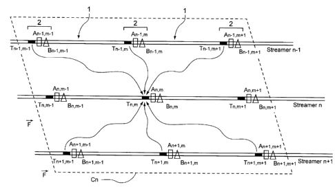
Figure 1 shows an array of streamers being
deployed (in the direction indicated by the arrow F).
. . . . . . .. .. . .
CA 02632861 2008-05-30
According to the deployment mode shown, the
streamers are deployed with a deployed length offset in
relation to one another (streamer n+l has a deployed
length greater than that of streamer n, itself having a
5 deployed length greater than that of streamer n-1...).
Each streamer includes evenly distributed (e.g.,
every 300 metres (or ever 2 sections)) distance-
measuring means T and navigational control means B, the
latter, according to this embodiment, being "birds,"
10 e.g., such as those described by the patent document
published under the number FR-2 870 509.
The distance-measuring means use an acoustic
measurement system. This acoustic measurement is
bidirectional.
15 Furthermore, an electrical power cable is built
into the sheathing of the streamers so as to power all
of the components distributed on the streamers, and in
particular the distance-measuring means, from a
generator on-board the towing vessel (which avoids
using the stand-alone batteries).
According to this embodiment, the measuring means
are acoustic transducers which communicate with one
another such that, at various moments, the transducers
Tn-l,m-l; Tn-l,m; Tn-1,m+1 of a streamer n-1 and the
transducers Tn+l,m-1; Tn+1,m; Tn+l,m+1 of a streamer
n+1 each transmit a signal for the transducer Tn,m of a
streamer n.
To accomplish this, each transducer includes means
of transmitting and means of receiving an acoustic
signal.
CA 02632861 2008-05-30
16
The measurement of distance between the pieces of
equipment is carried out by any appropriate acoustic
measuring technique known by those skilled in the art.
According to the principle of the invention, the
method of assisting the deployment (or retrieval) of
the streamers includes a step (aided by computer
software means) for configuring a plurality of cells Cn
each defined by:
- a central position corresponding to the position
of a transducer Tn,m of a streamer n;
- peripheral positions corresponding to other
transducers in the vicinity of transducer Tn,m: in the
case significant longitudinal and/or lateral offsets
between streamers, each cell is advantageously defined
by at least two, preferably three, or even four or more
transducers of each streamer adjacent to transducer
Tn,m, namely transducers Tn-l,m-1; Tn-l,m; Tn-l,m+l and
transducers Tn+l,m-1; Tn+l,m; Tn+l,m+l of streamer n-1
and streamer n+1, respectively.
It is understood that cell configuration step (or
that a cell reconfiguration step) can also consist in
defining (modifying) the number of peripheral
transducers taken into account in the definition of a
cell.
The method thus offers a large degree of
flexibility, in that it enables the configuration of
the cells to be adapted to the situation (isolated or
non-isolated deployment, isolated or non-isolated
retrieval, turning...) .
Furthermore, reference distances between the
central positions and the peripheral positions are
CA 02632861 2008-05-30
17
specified. Typically, it is attempted to maintain a
spacing of approximately 100 metres between the
streamers, the reference distances being calculated
accordingly (in particular, on the basis of the spacing
between transducers), the tendency, however, being to
reduce this spacing to values of the order of 30 to 50
metres.
During the course of deployment (or retrieval) of
the streamers, measurement of the positions of the
streamers relative to one another is thus carried out
gradually by analysis of the central and peripheral
positions in relation to the reference distances, this
being done for each cell Cn, in synchronized fashion,
and over the entire array of streamers.
In addition, in the case of synchronization of the
various components of the system, this synchronization
can be ensured by a controller on-board the towing
vessel.
More precisely, a synchronization order is sent to
all of the transducers T, this order having the
capability of consisting of a transmitting order, a
receiving order or an idle mode order.
The distance measurements are carried out for the
transducers concerned, the corresponding data being
stored by the transducers having received a receiving
order.
The cycle is repeated with other transducers until
all of the transducer positions are mapped and all are
analyzed by an operator on the boat, thus providing a
precious decision-making tool.
CA 02632861 2008-05-30
18
If the mapping of the array of streamers shows
that some of them deviate from the reference distances,
the most well-positioned "birds" can be used to bring
the corresponding streamer or streamers back to the
reference distance or distances.
It is noted that the "birds" (or any other
navigation control means for the streamers) are capable
of correcting the position of the streamers, by
imparting a lateral movement thereto and/or a variation
in the position thereof, depending on the depth of same
in the water.
In addition, based on the evolution of the
deployment (or retrieval) of the streamers and/or the
mapping of the array, steps for reconfiguring the cells
Cn are carried out, the relative positions of the
transducers having been modified, for example, to the
point of having to declare new transducers in
peripheral positions for a transducer in central
position.
A reconfiguration step such as this can be
initiated:
- by an operator;
- on the basis of deployment information provided
by an on-board system, and used by an operator who
initiates and/or validates the reconfiguration of the
cells: this information can be obtained by an operator
who positions a bird on a streamer (in deployment phase
from the deck of the boat), and who declares, via an
action on a graphic interface, the acoustic node/bird
to have been deployed, i.e., as being ready to go into
the water;
CA 02632861 2008-05-30
19
- automatically: on the basis of deployment
information from the distance-measuring means or
deployment information from the linear antennas: the
"winches" (deployment/retrieval drums for the streamers)
are then equipped with means of measuring the
deployment/retrieval rate and/or length of the
streamers and provide measurement signals to
calculating means which determine the activation of
cell reconfiguration; this information corresponds
either to a deployed distance of the streamer, or to a
deployment rate. It can be provided by the winches or
any other means on-board or built-into the streamer
(GPS, compass...) ;
- automatically: on the basis of the analysis of
the actual acoustic distance measurements of the system
(relative positioning of the streamers in relation to
one another): in this case, the system analyzes all of
the acoustic distances at its disposal and
automatically adapts the array.
In actual practice, these reconfiguration steps
are carried out repeatedly and iteratively.
In particular, in the particular case of a turning
course of the vessel, as shown schematically in figure
3, this or these reconfiguration steps can also consist
in redefining the reference distances. As a matter of
fact, during turning courses, the streamers tend to
move away from one another as the distance from the
towing vessel increases. Consequently, the cells tend
to become larger and it is necessary to take this
aspect into consideration in the configuration thereof,
by modifying the reference distances.
CA 02632861 2008-05-30
Another reconfiguration phase can again be carried
out in another particular case, involving the isolated
deployment/retrieval of a streamer from an existing
array.
5 In this case, the streamer in question is
deployed/retrieved in "phantom" mode: the transducers
that it carries are rendered "passive" for mapping the
array of streamers and, in configuring the cells,
account is taken of the positions of the transducers
10 carried by the streamer which is immediately adjacent
thereto. Thus, in the example of figure 2, since
streamer n-1 is being retrieved in the direction
indicated by the arrow F, transducers Tn-l,m-1; Tn-l,m;
Tn-1,m+1... are configured as receivers only, the
15 acoustic signals emitted by the adjacent streamers
enabling the positioning of the streamer to be
controlled during retrieval. In the same way, in
configuring the cells, the latter are reconfigured such
that, for a cell having the transducer Tn,m as the
20 central position, the positions considered to be
peripheral, which are occupied by transducers Tn-1,m-1;
Tn-1,m; Tn-l,m+l are substituted by the positions
occupied by transducers Tn-2,m-1; Tn-2, m; Tn-2,m+1. Of
course, the corresponding reference distances are
likewise redefined.
According to a preferred implementation of the
invention, each streamer also carries closed-loop
control means A, distributed over the length of the
streamer and placed in the vicinity of a "bird,"
whereby the closed-loop control means An,m-l; An,m;
An,m+1 of a streamer A communicate locally with the
CA 02632861 2008-05-30
21
"birds" Bn,m-1; Bn,m; Bn,m+l of the same streamer,
respectively, after processing of the data transmitted
by the array of adjacent transducers.
It is understood that the transducers T
communicate with one another so as to determine the
respective positions thereof, and then transmit the
data relating to the position of same to the closed-
loop control means A corresponding locally thereto
(An, m+l for transducer Tn, m+l ; An,m for Tn, m; ...) , the
latter transmitting an instruction to the corresponding
bird (Bn,m+l for the closed-loop control means An,m+l;
Bn,m for An,m;...) .
In this way, the streamers can be kept at a
desired distance from one another, the closed-loop
control means A being configured to keep this distance
in a straight-line configuration, like the one shown in
figure 1, as well as in a turning configuration, like
the one shown in figure 3.
It is noted that the streamers consist of the
assembly of sections 1 some of these sections of which
are interconnected via connecting elements 2.
According to a preferred solution, each connecting
element integrates an embedded electronics system
comprising closed-loop control means A, and carries a
bird B. The connecting elements also have electrical
connectors so as to enable power to be progressively
supplied to the sections, from an electrical generator
on-board the towing vessel.
Furthermore, transducers T are mounted on the
sections in the vicinity of each connecting element,
e.g., at a distance of approximately 30 cm (these being
CA 02632861 2008-05-30
22
similarly capable of being integrated directly into the
connecting elements according to one foreseeable
alternative).
According to one preferred embodiment, pressure
sensors are integrated into the connecting elements so
as to measure the depth of the streamer at the location
of the bird in question.
The depth-related data is transmitted to
processing means carried by the streamers, these
processing means enabling a projection of the position
of the transducers in a horizontal plane to be produced
by means of an appropriate algorithm.
According to one preferred embodiment, these means
of processing depth-related data are integrated into
the embedded electronics system of the connecting
elements.
Furthermore, the connecting elements each carry
(or only some of them) a compass enabling acquisition
of bearing information. This information, combined with
that relating to the positions of the transducers, may
enable repositioning of the streamers to be optimized
by detecting the configuration of the streamers
relative to one another (in a straight line or when
turning).