Note: Descriptions are shown in the official language in which they were submitted.
CA 02632865 2008-06-12
68226-12E
CRIB SHIELD SYSTEM
AND OTHER BREATHABLE APPARATUS
This is a divisional application of Canadian patent application No. 2,549,343
filed
December 16, 2003.
It is to be understood that the expression "the present invention" or the like
as used in
this specification refers not only to the subject matter of this divisional
application but to that
of the parent application and any other divisional application also.
Backaround of the Invention
The present invention relates to cribs and other usable objects (e_g., child
usable objects). More particularly, the present invention pertains to crib
attachments
and other breazhable apparatus that, for example, protect infants or young
children
from harnz, e.g., crib attachments that prevent or protect infants or young
children
when in a crib from getting into one or- more problematic situations, e.g.,
getting
liinbs extended and caught between crib slats or chewing on crib rails,
siblings poking
shaip objects into the crib, etc.
For example, conventional baby cribs include side rails that are made up of
top and bottom horizontal bars interconnected by a series of spaced supports
(e.g.,
vertical slats). Frequently, babics and toddlcrs, while sleeping or playing in
their
cribs, intentionally or accidentally extend their limbs out of the crib
between the slats
and have difficulty drawing them back into the crib. If this occurs when the
child is
sleeping, the extended limbs will remain uncovered and become cold, and the
child
will be ultimately awakened. Many cribs also have headboards and footboards
that
are also nlade with spaced-apart supports and the baby may also extend its
arms or
legs out of the crib between these slats.
Although various types of apparatus have been used to prevent such
problematic situations (e.g., extension of limbs outside of the crib through
the spaced-
apart supports), many of such apparatus exhibit their own problems. For
example, as
described herein, ventilation may be problematic (e.g., such as that leading
up to and
resulting in suffocation). Foi- example, crib bunipel- pads are widely used in
cribs for
1
CA 02632865 2008-06-12
WO 2004/056237 PCTIUS2003/040461
protecting a child from injury caused by bodily impact of the child against
the sides of
the crib that define the interior boundary of the crib. However, in many
cases, such
crib bumpers do not allow for adequate ventilation within the crib and
obstruct view
of the child.
Infants usually breathe through the nasal passages. However, during crying or
in the event their nasal passages are blocked, infants may breathe through
their oral
cavities. Mechanical resistance suffocation takes places when respiration is
interrupted if these passages are both blocked externally by an object. When
respiration is interrupted, CO7 levels in the blood rise. The body's response
to this
elevation in COz levels is to attempt more rigorous respiration. If the agent
of
suffocation is not renioved, the incident may be fatal after two or three
minutes.
Further, the accumulation of CO2 or other dangerous gases inside the crib may
be a
possible cause of sudden infant death syndrome (SIDS). Existing crib
apparatus, such
as crib bumper pads, tend to trap dangerous gases inside the crib. Further,
such
apparatus may bloek the passages of infants under certain circumstances.
Various types of other crib apparatus have been described and attempt to
reduce one or more of the above problems. For example, such apparatus are
described in U.S. Patent No. 5,881,408 to Bashista et al., entitled "Mesh Crib
Liner,"
issued 16 March 1999; and U.S. Patent No. 6,178,573 to Wagner et al., entitled
"
Ventilation Upgrade Kit for a Crib Bumper and Method of Using It."
Summary of the Invention
The present invention, as described herein, addresses the problems described
above and other problems of prior art systems and methods which will become
apparent to one skilled in the art from the description below. Generally, the
present
invention provides a crib shield systein that is breathable, as well as other
breathable
apparatus. (e.g., objects such as blankets, toys, etc.). For example, one crib
shield
system is for use with a crib that includes a first and second side rail, a
headboard,
and a footboard connected and sized for receiving a mattress therein. At least
one of
the first and second side rails includes a top bar and a plurality of spaced
support
elements.
The crib shield system according to the present invention for use with the
crib
2
CA 02632865 2008-06-12
76433-101
includes a first and second side. panel, wherein each of the fii-st and second
side panels
is configured as a separate panel to cover at least a substantial portion of a
corresponding side rail with a mesh-type material comprising openings too
small to
permit an infant to insert a finger or toe therethrough, and wherein the first
side panel is not
connected to the second side panel. Each of the first and second side panels
includes at least one
fastening apparatus that extends along an entire edge of the side panel to
attach the side panel to
the top bar of a corresponding side rail. Further, each of the first and
second side panels includes
at least one other fastening apparatus for securing the side panel to the
corresponding side rail.
In one embodiment of the crib shield system, the system further includes at
least one of a first and second end panel. Each of the at least one first and
second end
panels is configured as a separate panel to cover at least a substantial
portion of a
corresponding headboard or footboard with a mesh-type material having openings
too
small to pernut an infant to insert a finger or toe therethrough. Each of the
first and
second end panels includes at least one fastening apparatus that extends along
an
entire edge of the panel to attach the panel to a spaced support element of a
corresponding headboard or footbo,-ffd, and fi.irther wherein each of the
first and
second end panels includes at least one other fastening apparatus for
sectiring the
panel to the coiTesponding headboard or footboard.
In yet another embodiment, the at least one other fastening apparatus of each
of the first and second end panels is provided at one or more positions along
an edge
opposite the entire edge to allow a user to pull the panel taut across the
corresponding
headboard or footboard when the at least one fastening apparatus extending
along the
entire edge of the panel is attached to the spaced support element of the
corresponding headboard or footboard. Further, it is confignred to secure the
panel to
another spaced support element of the coiYesponding headboard or footboard
using
the at least one other fastening apparatus.
hi yet anotlier embodiment of the system, the at least one othei- fastening
apparatus of eacli of the first and second side panels is pi-ovided at one or
more
positions along an edge opposite the entire edge to allow a user to pull the
panel taut
across the corresponding side i-ail -when the at least one fastening apparatus
extending
along the entire edge of the panel is attached to the top rail of a
corresponding side
rail. Further, it is configui-ed to secure the panel to another portion of the
3
CA 02632865 2008-06-12
76433-101
corresponding side rail using the at least one other fastening apparatus.
Another crib shield system according to the present invention for use with a
crib (e_g., wherein each of the first and second side rails extend along a
length of the
crib between the headboard ancl the footboard) includes a fii-st panel and a
second
panel. The first panel is configured to cover at least a portion of the first
side rail and
to extend along substantially the length of the crib. Further, the first panel
is formed
substantially of a mesh-type material having openings too small to permit an
infant to
insert a finger or toe therethrough and includes at least one fastening
apparatus to
attach a first end of the first panel to a first portion of the first side
rail. Yet furtlier,
the first panel includes at least one other fastening apparatus for securing a
second
end opposite of the first end of the first panel to a second portion of the
first side rail.
The second panel is separate from and not connected to the first panel and is
configured
to cover at least a portion of the second side rail and to extend at least
along the length of the
crib. The second panel is substantially formed of a mesh-type material having
openings too small to pennit an infant to insert a finger or toe therethrough
and
second panel includes at least one fastening apparatus to attach a first end
of the second panel to
the crib. Further, the second panel includes at least one other fastening
apparatus for securing a
second end opposite of the first end of the second panel to the crib.
In one embodiment of this crib shield system, the second panel is further
configured to cover at least a portion of the headboard and footboard, the at
least one
fastening apparatus of the second panel is configured to attach the second
panel to
one of the headboard and footboard, and the at least one other fastening
apparatus of
the second panel is configured to secure the second panel to the other of the
headboard and footboard.
In another embocliment of the system, the at least one fastening apparatus of
the second panel is configured to attach the second panel to a spaced support
element
that forms a part of the headboard, and the at least one other fastening
apparatus of
the second panel is configured to attach the second panel to another spaced
support
element that forms a part of the footboard.
Yet further, in another embodiment, the at least one fastening apparatus of
the
first panel is configured to attach the first end of the first panel to a
spaced support
4
CA 02632865 2008-06-12
76433-101(S)
element of the first side rail proximate the headboard, and
the at least one other fastening apparatus of the first
panel is configured to attached the second end of the first
panel to another spaced support element of the first side
rail proximate the footboard.
Further, in one or more embodiments of this crib
shield system, at least the first panel includes a width
that is less than the length of a spaced support element of
the first side rail or a width that is less than one half
the length of a spaced support element of the first side
rail.
Another crib shield system for a crib that
includes at least a first side rail, wherein the at least
the first side rail comprises a plurality of spaced support
elements (e.g., used in defining an interior boundary
extending proximate and around a periphery of a mattress
disposed within the crib) includes at least one panel
configured to cover at least a portion of the plurality of
spaced support elements of the first side rail and to extend
along at least a portion of the interior boundary. The at
least one panel is formed substantially of a breathable
integrated padded mesh material and includes at least one
fastening apparatus for securing the at least one panel to
the crib. In an exemplary embodiment, the at least one
panel comprises a width that is less than a length of a
spaced support element of the first side rail that is in a
vertical position as part of the crib. This width may be
less than one-half the length of the spaced support element.
In one embodiment of this system, the at least one
panel may include a first panel and a second panel. The
5
CA 02632865 2008-06-12
. 76433-101 (S)
first panel is siz-ed to cover at least a portion of the
plurality of spaced support elements that form a part of a
first side rail that defines at least a part of the interior
5a
CA 02632865 2008-06-12
76433-101
boundary and to extend along a substantial portion of a
length of the first side rail from a headboard to a
footboard of the crib. Further, the first panel includes at
least one fastening apparatus to attach a first end of the
first panel to one of the plurality of spaced support
elements of the first side rail, and also at least one other
fastening apparatus for securing a second end of the first
panel to another one of the plurality of spaced support
elements of the first side rail. The second panel is
separate from the first panel and is sized to cover at least
a portion of the plurality of spaced support elements that
form a part of a second side rail that defines at least a
part of the interior boundary and to extend at least along a
subst ant i a l pnrt i nn nf a length cf t.hP sPrnnci side ra i l from
a headboard to a footboard of the crib. The second panel
includes at least one fastening apparatus to attach the
second panel to one of the plurality of spaced support
elements of the crib, and also includes at least one other
fastening apparatus for securing the second panel to another
one of the plurality of spaced support elements of the crib.
In yet another embodiment of the system, the
second panel is further sized to cover at least a portion of
the headboard and the footboard that defines at least a part
of the interior boundary. For example, the at least one
fastening apparatus of the second panel is configured to
attach the second panel to a spaced support element of the
headboard and the at least one other fastening apparatus of
the second panel is configured to secure the second panel to
a spaced support element of the footboard.
In one or more embodiments of the apparatus or
systems described herein, the plurality of spaced support
elements covered, at least in part, by the at least one
panel form a part of a side rail that is movable relative to
6
CA 02632865 2009-09-23
78643-18E(S)
a remainder of the crib. Further, one or more of the
fastening apparatus may include a hook and loop fastener.
Further, one or more of the panels of the systems
described herein may be formed of a breathable integrated
padded mesh material alone or in combination with one or
more other breathable materials. For example, the mesh-type
material may include a front substructure, a back
substructure, and a pile substructure integrated with and
extending between the front and back substructures. Each of
the substructures allows air to substantially move
effectively therethrough.
Yet further according to the present invention,
various breathable apparatus may be provided. For example,
an apparatus may include a body portion that includes one or
more surfaces. The body portion is, for example, used
proximate the mouth of a human being. The body portion may
form at least a substantial portion of at least one of a
blanket, a baby carrier apparatus, baby clothing, a toy,
etc. Further, substantially all of the one or more surfaces
of the body portion may be formed of a breathable integrated
padded mesh material alone or in combination with one or
more other breathable materials.
In one invention embodiment, there is provided an
apparatus for use with a mattress comprising: a planar body
portion configured as a sheet for use on a mattress
proximate the mouth of a human being as the human being is
lying thereon, wherein the planar body portion comprises a
plurality of layers of material laid flat against each other
to provide at least upper and lower surfaces of the body
portion, wherein the plurality of layers of material
comprise: a layer of a breathable integrated padded mesh
6a
CA 02632865 2009-09-23
78643-18E(S)
material, wherein the breathable integrated padded mesh
material comprises a front substructure, a back
substructure, and a pile substructure integrated with and
extending between the front and back substructures, wherein
each of the substructures allows air to substantially move
effectively therethrough; and a first layer of material laid
flat against the layer of breathable integrated padded mesh
material, the first layer of material decreasing air
movement through the planar body portion in a wet state to a
greater degree than the layer of the breathable integrated
padded mesh material.
In a further invention embodiment, there is
provided an apparatus comprising: a planar body portion
configured as a substantial portion of one of a changing
pad, a play mat, a sleeping mat, and a bath mat, wherein the
planar body portion comprises a plurality of layers of
material laid flat against each other to provide at least
upper and lower surfaces of the body portion, wherein the
plurality of layers of material comprise: a layer of
breathable integrated padded mesh material, wherein the
layer of breathable integrated padded mesh material
comprises a front substructure, a back substructure, and a
pile substructure integrated with and extending between the
front and back substructures, wherein each of the
substructures allows air to substantially move effectively
therethrough; and at least one layer of material coupled to
the layer of breathable integrated padded mesh material such
that the at least one layer of material is adjacent to at
least one of the front substructure or the back
substructure, the at least one layer of material decreasing
air movement through the planar body portion in a wet state
to a greater degree than the layer of the breathable
integrated padded mesh material.
6b
CA 02632865 2009-09-23
78643-18E (S)
In a further invention embodiment, there is
provided an apparatus comprising: a planar body portion
configured as a substantial portion of a wearable blanket,
wherein the planar body portion comprises a plurality of
layers of material laid flat against each other to provide
at least upper and lower surfaces of the body portion,
wherein the plurality of layers of material comprise: a
layer of breathable integrated padded mesh material, wherein
the layer of breathable integrated padded mesh material
comprises a front substructure, a back substructure, and a
pile substructure integrated with and extending between the
front and back substructures, wherein each of the
substructures allows air to substantially move effectively
therethrough; and at least one layer of material coupled to
the layer of breathable integrated padded mesh material such
that the at least one layer of material is adjacent to at
least one of the front substructure or the back
substructure, the at least one layer of material decreasing
air movement through the planar body portion in a wet state
to a greater degree than the layer of the breathable
integrated padded mesh material.
In another invention embodiment, there is provided
a baby carrier apparatus comprising: a body portion
defining a volume to receive a child within the defined
volume, wherein a majority of the body portion is formed of
a breathable integrated padded mesh material, the breathable
integrated padded mesh material being positioned such that
it is next to the child's face when the child is received in
the defined volume; and an attachment mechanism to attach
the body portion to a person that will carry the child
received in the defined volume.
6c
CA 02632865 2009-09-23
78643-18E (S)
In a still further invention embodiment, there is
provided a toy apparatus comprising: a three dimensional
body portion configured for use proximate the mouth of a
child, wherein the three dimensional body portion comprises:
a breathable integrated padded mesh material covering a
majority of the three dimensional body portion; and a
padding material covered at least in part by the breathable
padded mesh material.
The above summary of the present invention is not
intended to describe each embodiment or every implementation
of the present invention. Advantages, together with a more
complete understanding of the invention, will become
apparent and appreciated by referring to the following
detailed description and claims taken in conjunction with
the accompanying drawings.
BRIEF DESCRIPTION OF THE DRAWINGS
Figure 1 shows a perspective view of one
embodiment of a low crib shield
6d
CA 02632865 2008-06-12
WO 2004/056237 PCT/US2003/040461
system attached to a crib with a side rail of the crib in a raised state.
Figure 2A is a top view of one embodiment of a first side panel of the low
crib
shield system shown in Figure 1 in an unattached position laid flat.
Figure 2B is a top view of one embodiment of a second side panel of the low
crib shield system shown in Figure 1 in an unattached position laid flat.
Figures 2C-2F show details of one embodiment of an integrated padded mesh
material that may be used in forming the side panels and the crib shield
system shown
in Figures 1 and 2, as well as other apparatus or objects described in the
other figures.
Figures 3A-3C illustrate the attachment of the first and second side panels
shown in Figures 1 and 2 to a crib according to one embodiment of the present
invention.
Figure 4 shows a perspective view of one embodiment of a full crib shield
system attached to a crib with the mattress of the crib in a lowered position
and a
moveable side rail in a raised state.
Figure 5 shows a top view of one embodiment of a side panel for use in the
full crib shield system shown in Figure 4 according to the present invention
in an
unattached position laid flat.
Figures 6A-6F show various illustrations for use in describing the attachment
of the side panel shown in Figure 5 to a crib side rail according to one
embodiment of
the present invention.
Figure 7 shows a top view of an end panel for use in the full crib shield
system
shown in Figure 4 according to the present invention in an unattached position
laid
flat.
Figure 8 shows an illustration for use in describing attachment of the end
panel shown generally in Figure 7 to a headboard or footboard of a crib
according to
one embodiment of the present invention.
Figure 9 is a diagram showing a general embodiment of a breathable apparatus
according to the present invention.
Figures l0A-lOC show illustrations of a breathable blanket and a breathable
comforter, along with more detail thereof, respectively, according to the
present
invention.
7
CA 02632865 2008-06-12
WO 2004/056237 PCT/US2003/040461
Figures 11A-11F show various illustrations of breathable apparatus, such as
apparatus for carrying or receiving a small child (e.g., a baby) according to
the
present invention.
Figure 12 shows an illustration of one embodiment of a breathable toy
according to the present invention.
Figure 13 shows a diagram of one embodiment of breathable clothing or
wearables according to the present invention.
Detailed Description of the Embodiments
One or more embodiments of crib shield systems shall be described with
reference to Figures 1-8. Thereafter, various embodiments of other breathable
apparatus shall be described with further reference to Figures 9-13.
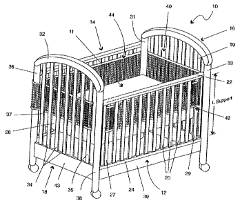
Figure 1 shows a conventional crib 10. The crib 10 includes two side rails 12,
14, a footboard 16, and a headboard 18. The side rails 12, 14 extend between
the
footboard 16 and headboard 18 along a length thereof. The headboard 18,
footboard
16, and side rails 12, 14 are connected and sized for receiving a mattress
within an
interior 11 of the crib 10.
Generally, the side rails 12, 14, footboard 16, and headboard 18 define an
interior boundary extending proximate and around a periphery of the mattress
26
disposed within the crib 10. The mattress 26 is supported within the crib 10
by
various structure not shown in Figure 1. For example, a bottom structural
member
may be supported at one or more positions about the interior boundary of the
crib 10
(e.g., elements attached to corner posts 36, 38, 31, 33) or in any other
fashion. In
many conventional cribs 10, the mattress 26 and/or a supporting member
therebelow
may be raised and/or lowered. For example, as shown in Figure 1, the mattress
26 is
in a raised state. On the other hand, as shown in Figure 4 (to be described
further
herein), the mattress is shown in a lowered state. The lowered state is closer
to the
ground or floor upon which the crib 10 is positioned than the raised state.
The side rail 12 generally includes a top bar 22 and a bottom bar 24
positioned
substantially parallel to one another. A plurality of generally vertically-
spaced side
support elements 20 extend between the horizontal top bar 22 and horizontal
bottom
bar 24. The side rail 12 in many conventional cribs is moveable from a raised
state to
8
CA 02632865 2008-06-12
WO 2004/056237 PCT/US2003/040461
a lowered state. For example, the moveable side rail 12 allows a user to lower
the
side rail 12 in order to have easier access to a child lying on mattress 26.
As shown in
Figure 1, side rail 12 can be raised or lowered relative to support structure
element 39
and the remainder of the crib 10. The present invention allows for the side
rail 12 to
be moved from a lowered state to a raised state, or vice versa, even with the
crib
shield system 40 attached to the crib 10.
Side rail 14 may be similarly configured like that of side rail 12. In other
words, side rail 14 may be moveable from a lowered to a raised state, and vice
versa.
However, side rail 14 may also be in a stationary position fixedly attached to
corner
posts 36, 31. Likewise, side rail 12 may be moveable or in a fixed position.
As
moveable side rails are conventional configurations, no further description is
provided
with respect to the mechanisms for allowing such movement thereof. The crib
shield
systems described herein work with various mechanisms for moving side rails,
e.g.,
side and bottom latch systems and gliding side mechanisms.
Headboard 18 of crib 10 includes an upper bar 32 (e.g., in a decorative curved
shape) as well as a bottom horizontal element 43, each connected in a fixed
position
to corner posts 36, 38. In a similar manner to the side rails 12, 14,
generally
vertically-spaced support elements 34 extend between the top bar 32 and the
horizontal element 43. It will be recognized that many cribs may or may not
have
spaced support elements that define a part of the footboard 16 or headboard
18. For
example, the headboard and footboard may be solid materials as opposed to
spaced-
apart supports. The footboard 16 is configured in a manner like that of
headboard 18
and includes corner posts 31, 33.
As shown in Figure 1, the plurality of spaced-apart side support elements 20,
34 of the side rails 12, 14 and the headboard and footboard 16, 18 are used to
define
the interior boundary extending proximate and around the periphery of the
mattress
26 disposed within the crib 10. In one embodiment, and as shown in Figure 1,
at least
one panel is sized for covering at least a portion of the plurality of spaced-
apart side
support elements and configured to extend along at least a portion of the
interior
boundary. As is described herein, in one preferred enibodiment, substantially
the
eiitire panel is formed of a breathable integrated padded mesh material and
the panel
includes at least one fastening apparatus for securing at least one panel to
the crib 10.
9
CA 02632865 2009-02-13
68226-12E(S)
As used herein, the term mattress may include any structure disposed within
crib 10 and upon which objects and/or human beings may be placed. In other
words,
mattress refers to any structure and not just a soft sleeping apparatus. For
example,
the crib could be configured into a playpen-type structure with a solid hard
and/or flat
bottom that is, for example, lowered very close to the floor. As such, and as
used
herein, a crib can be equated to and encompasses the various structures
similar to a
crib, such as those for containing a small cliild (e.g., playpens, portable
cribs,
convertible cribs, round cribs, or other structures including, for exanlple,
spaced-apart
side supports which require an apparatus or system such as that described
herein).
As further shown in Figure 1, crib shield system 40 is attached to crib 10
along a substantial portion of the interior boundary of the crib 10 defined by
the
headboard 18, footboard 16, and side rails 12, 14. As shown in Figure 1, a
first side
pane142 is attached to side rail 12. Further, a second side pane144 is
attached for
coverir-g side rail 14, footboard 16, and headboard 18. However, one skilled
in the art
will recognize that the second side pane144 may also be configured to cover
just the
second side rail 14 and the footboard 16 (e.g., such as when the headboard
181acks
vertical spaced-apart side support elerrients), or may cover just side rail 14
and
headboard 18 (e.g., such as when footboard 161acks spaced-apart side support
elements). In otlier words, the configuration of the second side pane144 niay
differ
depending upon the configuration of crib 10 upon which it is attached.
Figure 2A shows the first side pane142 in an unattached laid flat position.
The
first side pane142 includes a body 46 formed of a mesh-type material that
extends
along the length (L panel 1) from a first end 48 of the first side panel 42 to
a second
end 50 of the first side panel 42. The length (L panel 1) of the first side
panel 42 is
sized for allowing attachment to the side rail 12 of crib 10. For example, the
length
(L panel 1) is slightly longer than the distance between spaced-apart side
support
elements 27, 29. In sucli a manner, the first side panel 42 can be wrapped
about such
side support elernents 27, 29 and fastened thereto using hook and loop
closures 53,
54, as is further described herein with reference to Figure 3A.
The body portion 46 has a width (W panel 1) that is less than a length (L
support as shown in Figure 1) of a vertical spaced support element 20 of the
first side
rail 12. Preferably, the width (W panel 1) is less than one-half the length (L
support)
CA 02632865 2008-06-12
WO 2004/056237 PCT/US2003/040461
of the vertical spaced side support element 20.
The first side panel 42 includes a first fastening apparatus 52 at the first
end
48 of the first side panel 42 and a second fastening apparatus 54 at the
second end 50
of the first side panel 42. Fastening apparatus 52 includes fastening portions
53, 55,
such as hook and loop closures (e.g., Velcro). In one embodiment, fastening
apparatus 54 is the same as fastening apparatus 52, however, such closure
structures
may also be different.
Various fastening apparatus may be used to attach the first side panel as well
as the other panels as described herein to a crib. For example, various types
of
fastening apparatus may include hook and loop closures (e.g., Velcro), snaps,
buttons/buttonholes, ties, straps, buckles, zippers, etc. Although hook and
loop
fasteners are preferable, any other closure or fastener apparatus suitable for
attaching
panels to crib 10 may be used.
In one embodiment, a finishing edge material 58 is provided along the
pcriphery of the body portion 46. For example, as shown in Figurc 2A, a
finishing
edge material (e.g., a decorative material) may be used along edges 61-64.
Figure 2B shows the second side panel 44 in an unattached laid flat position.
The second side panel 44 includes a body portion 70 that extends along a
length (L
panel 2) from a first end 72 thereof to a second end 74 of the second side
panel 44.
The length (L pane12) of the second side pane144 is sized for allowing
attachment to
footboard 16 and headboard 18 and across side rail 14 of crib 10. For example,
the
length (L panel 2) is slightly longer than the combined lengths of the three
sides of
the crib 10 (i.e., the lengths of the footboard 16, headboard 18, and side
rail 14). In
such a manner, the second side pane144 can be wrapped about support elements
19,
35 and fastened thereto using hook and loop closures 76, 78, as is further
described
herein. Further, the second side pane144 has a width (W panel 2) that, at
least in one
embodiment, has substantially the same width as the width (W panel 1) of first
panel
42.
Further, second side panel 44 includes fastening apparatus 76 at first end 72
of
the second side pane144 and fastening apparatus 78 at the second end 74 of the
second panel 44. Such fastening apparatus 76, 78 are substantially similar to
the hook
and loop fasteners described with respect to first pane142. Further, in a like
manner,
11
CA 02632865 2008-06-12
WO 2004/056237 PCT/US2003/040461
finishing edge material 80 may be used around the perimeter of the body
portion 70
as shown by the finishing materia180 along edges 81-84.
The mesh-type material of the body portion 46 of first side panel 42 and body
portion 70 of second side panel 44 may include any suitable mesh-type material
that
provides breathable functionality. Breathable functionality refers to the
ability of the
material to allow air to substantially move effectively therethrough. As used
herein,
when air is indicated as substantially moving effectively through a material,
it is
meant that the material includes openings (e.g., mesh openings, open-
framework,
spaces between elements thereof, or even those that may not be visually
perceivable
openings but still allow a breathable function to occur) that do not impede
air
movement to an extent that would prevent a human being from breathing through
(e.g., when a human's respiratory openings (e.g., nose/mouth) are in direct
contact
with a material) such a material in order to prevent suffocation and further
that such
openings are too small to permit an infant to insert a finger or toe
therethrough. For
example, such materials may include cotton, silk, polyester, nylon, etc.
In one embodiment, the mesh-type material may include a mesh available
from Apex Mills, Inc. under the trade designation TA1 Mesh. However, other
various similar mesh materials (e.g., mesh material having suitable openings
are
available). A Suffocation Hazard Assessment was performed by RAM Consulting
(Oak Brook, IL) (e.g., the Assessment is further described herein and for
which
protocol is available from RAM Consulting) on the TAI Mesh resulting in
average
readings of 1.6 cm H20 and, for an upper specification limit of 5 cm H20, a Z-
value of
9.0 was obtained.
Preferably, the mesh-type material is a breathable integrated padded mesh
material 300 (e.g., a padded spacer mesh), such as that show generally in
Figures 2C-
2F. The breathable integrated padded mesh material 300 includes openings 349
on a
front substructure 391 thereof, as shown in top view of the material 300 of
Figure 2C.
As shown in the cross-section of the breathable integrated padded mesh
material 300
in Figure 2F, the material 300 further includes a back substructure 392. A
pile
substructure 393 is integrated with and extends between the front and back
substructures 391, 392. Each of the substructures (e.g., the front, back, and
pile
substructures) allows air to substantially move effectively therethrough. The
material
12
CA 02632865 2008-06-12
WO 2004/056237 PCT/US2003/040461
300 is further shown in the perspective views of Figures 2D-2E.
It will be recognized that the thickness of the padded mesh material may vary,
as well as for other materials described herein. For example, more padding may
create a softer more plush effect with slightly different
breathability/ventilation
properties and more opaqueness (e.g., less light transmissive) whereas less
padding
may create more breathability and buoyancy with less opaqueness (e.g., more
light
transmissive). Preferably, the panels described herein are at least somewhat
transparent such that at least motion of the child in the crib can be seen.
Yet further, the padded mesh material is collapsible. As such, when installed
or uninstalled, should a child stand on it, the material will collapse. This
reduces the
risk of the mesh material being leverage to a climbing infant (unlike most
conventional bumpers).
In one embodiment, the breathable integrated padded mesh material 300 is a
woven polymeric fiber mesh material that includes larger openings on the front
substnicture 391 than on the back subslructure 392 and to which such
substructures
391, 392 are woven using the fibers that are provided as part of pile
substructure 393.
In such a manner, these fibers that form a part of the pile substructure 393
are
integrated with and extend between front and back substructures 391, 392. In
other
words, they form a unitary sti-ucture. This is substantially different than a
structure
whereby a mesh material or some other material is provided as the back or
front
covering with a pad material therebetween (e.g., a pad quilted in between a
front and
back material or a pad laniinated between a front and back material). Such a
layered
structure is not, and does not, provide the same functionality as an
integrated (i.e.,
unitary) breathable padded mesh material 300, such as shown in Figures 2C-2F.
In one enibodiment, for example, the breathable integrated padded mesh
material 300 may include a padded spacer mesh available from Apex Mills, Inc.
under the trade designation DNB27 Spacer Mesh. However, other various similar
padded spacer mesh materials are available.
In another embodiment, the mesh-type material is a breathable integrated
padded mesh material in combination with one or more other material layers.
For
example, the breathable integrated padded mesh material may be used in
combination
with one or more layers of other material adjacent to (e.g., one material laid
flat
13
CA 02632865 2008-06-12
WO 2004/056237 PCT/US2003/040461
against the other) either the front substructure and/or back substructure of
the
breathable integrated padded mesh material. In various embodiments of such a
combination, one or more layers of material may be used adjacent the front
substructure, one or more layers of material may be used adjacent the back
substructure, or one or more layers of material niay be used adjacent the
front
substructure and the back substructure. For example, such additional layers
may be
layers of cotton material, knit jersey material, etc. Such additional material
layers
may provide additional benefits such as, for example, thermal properties with
breathability.
Further, for example, the breathable integrated padded mesh material when
used alone, or in combination with one or more additional layers, may be any
breathable integrated padded mesh material that has a suffocation resistance
level of
less than about 15 cm H20, and preferably less than about 5 cm H20. Such a
suffocation resistance is determined according to the RAM Consulting Virtual
Child
Suffocation Hazard Assessment Model which is a physical model and testing
methodology that quantitatively assesses the potential suffocation hazards
posed by
various types of materials. The details of this Model are available from RAM
Consulting (Oak Brook, IL). Further, according to this Model, Z-values are
determined that are statistical measurement tools that describe and predict
product
performance in relation to its specification limit (e.g., such as those
described below).
For example, the suffocation resistance limit of 5 cm H20 is an upper
specification
limit for materials or products that foreseeably are used and/or intended for
young
infants with high accessibility; and further, the suffocation resistance limit
of about 15
cm H20 is an upper specification limit for other materials or products (e.g.,
those for
toddlers). A Z-value of 4.0 or greater with the corresponding upper
specification
limit for each applicable testing technique is required for a product to be
classified as
a very low suffocation risk. The details regarding the determination of Z-
values are
available from RAM Consulting (Oak Brook, IL).
Suffocation Hazard Assessment was performed by RAM Consulting (Oak
Brook, IL) on various configurations using the breathable integrated padded
mesh
material available from Apex Mills, Inc. under the trade designation DNB27
Spacer
Mesh.
14
CA 02632865 2008-06-12
WO 2004/056237 PCTIUS2003/040461
Configuration 1: Single Layer of Padded Spacer Mesh
Configuration 2: Layer 1: Padded Spacer Mesh
Layer 2: Cotton
Configuration 3: Layer 1: Knit Jersey
Layer 2: Padded Spacer Mesh
Layer 3: Cotton
Configuration 4: Layer 1: Cotton
Layer 2: Padded Spacer Mesh
Layer 3: Cotton
Configuration 5: Layer 1: Knit Jersey
Layer 2: Padded Spacer Mesh
Layer 3: Knit Jersey
Configuration 6: Layer 1: Padded Spacer Mesh
Layer 2: Flannel
Fabrics tested: Knit Jersey - Manufacturer: NATEX
Content: 50% Polyester/50% Cotton Knit Jersey
Style#: INT
Cotton - Manufacturer: SOUTHERN BELLE
Content: 100% Cotton
Style#: L93N67
Flannel - Manufacturer: QUILTERS CORNER
Content: 100% Cotton
Style#: RN41324
A screening was performed on all configurations in both a dry and wet state.
The spacer padded mesh when layered with fabrics resulted in a satisfactory
reading
based on values in cm H20, wherein the specification upper limit for products
young
children are intended to lie on is equal to 5 cm H20 (e.g., mattress pads or
items young
infants are intended to have their face on) and wherein the specification for
products
young children are not intended to lie on is equal to 15 cm H20.
CA 02632865 2009-02-13
68226-12E(S)
Four individual readings were performed with an average being determined.
Dry state readings did not register, thus presenting very low hazard when the
configurations were dry (i.e., under the 5 cm H20 specification limit). In the
wet state
(after application of 8 ml of sprayed on water), the average readings for the
configurations were between 4.6 cm 1120 and 6.2 cm I120.
For the individual single layer of spacer padded mesh, average readings of 1.7
cm HZ0 were taken. Furtlier, for an upper specification limit of 5 cm H20, a Z-
value
of 9.5 was obtained.
As shown in Figure 1, the first side pane142 is attached to first side rail 12
by
wrapping first end 48 of the first side panel 42 about spaced side support
element
27 and mating the hook aud loop fastener portions 53, 55 as shown in Figure
3A. The
second end 50 of first side panel 42 is wrapped around side support element 29
and
fastening apparatus 54 is used to hold the first side panel in place. For
example, in
one embodiment, the fastening apparatus 54 is attached to the side support
element
27. Thcreaftcr, the user pulls the panel taut across the plurality of spaced
side support
elements 20 by pulling on the second end 50 containing the fastening apparatus
54.
Fastening apparatus 54 is the attached to stipport elenient 29 in such a
inanner to hold
the taut panel in place. As such, the first side panel 42 is prevented from
slipping
after being attached to the spaced side support elements 27, 29.
In at least one embodiment, the first side panel 42 is configured to cover at
least a portion of the first side rail 12 and to extend substantially along
the length of
the crib 10. As used herein when a panel extends substantially along the
length of the
crib 10, it will be recognized that the panel may not extend completely along
the
entire length, but may end proximate the headboard and footboard. For example,
depending upon the fastening techniques used, the panel may be attached a
short
distance from the corner posts of the crib (see panel 42 as shown in Figure
1).
In a like manner, second side panel 44 is attached to the crib 10. For
example,
the second end 74 of the second side panel 44 is wrapped about spaced support
element 35 of headboard 18. Fastening apparatus 78 (e.g., Velcro closures) is
used to
fasten the second end 74 about the support element 35.
Further, as shown in Figure 1, the body portion 70 of the second side panel 44
is fed to the inside of the crib 10 (e.g., to the inside portions of support
elements 34)
16
CA 02632865 2008-06-12
WO 2004/056237 PCT/US2003/040461
and thereafter fed to the outside of the crib 10 and around corner post 36.
The body
portion 70 is continued to be fed back into the inside of the crib 10 (e.g.,
to the inside
of the support elements of the second side rail 14) and thereafter fed once
again to the
outside of the crib 10 and around corner post 31 (see Figures 3B-3C).
Thereafter, the
body portion 70 of the second side panel 44 is fed to the inside of the crib
10 once
again at the footboard 16 and then wrapped around support element 19 of
footboard
16 in a similar manner to the fastening of the second side panel 44 around
suppor-t
element 35 of headboard 18.
One will recognize that the second side panel may be attached to any number
of different support elements, may be fed around and/or to the outside of one
or more
spaced support elements, and, as with the first side panel 42, is pulled taut
prior to
fastening to keep the second side pane144 in position. Further, the weaving of
the
second side panel 44 around the corner posts and/or around one or more of the
spaced
support elements also assists in maintaining the second side panel 44 in
position (e.g.,
in a position higher on the crib 10 when the mattress is raised relative to
the floor and
lower in the crib 10 when the mattress is lowered to the floor). In addition,
any of the
panels may be positioned such that a portion of the panel is below the upper
surface
of the mattress (e.g., a few centimeters below the surface along the side of
the
mattress) to assist in securing the crib and preventing arms and legs from
going under
the panel.
As shown in Figure 4, the crib 10 is substantially the same as that shown in
Figure 1 except that the mattress 26 is in a lowered position. However, the
side rail
12 is a side rail that can be lowered or raised, as desired. Like the crib
shield system
40 in Figure 1, crib shield system 100, shown in Figure 4, allows the side
rail 12 to be
moved even with the crib shield system 100 attached to crib 10.
Crib shield system 100 includes a first side panel 102 and a second side panel
104 for attachment to respective side rails 12, 14. Further, the crib shield
system 100
includes a first end panel 106 for attachment to the footboard 16 and a second
end
panel 108 for attachment to the headboard 18.
Figure 5 shows the first side panel 102 of crib shield system 100 in an
unattached laid flat position. The first side panel 102 includes a body
portion 120
formed of a mesh-type material. In one embodiment, the mesh-type material is
an
17
CA 02632865 2009-02-13
68226-12E (S)
open framework material that includes openings too small to perniit an infant
to insert
a finger or toe therethrough. However, any mesh-type material described herein
may
be used as well.
The body portion 120 extends along a length (L panel 1) extending fronl a
first
end 122 of the first side panel 102 to a second end 124 thereof. Further, the
laid flat
first side panel 102 has a width (W panel 1) that is sized to cover at least a
substantial
portion of side rail 12.
As used herein, when referring to the covering of a substantial portion of a
side rail (or headboard or footboard, at least two-thirds of the side rail 12
is covered.
However, the first side panel may cover less than a substantial portion. For
example,
the first side panel may cover just a majority of the entire side rail 12.
The first side panel 102 further includes a fastening apparatus 126 that
extends
along an entire edge 144 of the side panel 102 for use in attaching the side
panel 102
to the top bar 22 of the side rail 12, as is shown in further detail in
Figures 6A fill.
The fastening apparatus 126, at least in onc embodiment, inclndes first and
second
fastening portions 147, 148 that are both for mating with one another in order
to hold
the first side panel 102 in a fixed position relative to side rail 12.
As shown in Figure 6A, the fastening apparatus 126 includes a padded portion
150 that is wrapped around top rail 22 such that first and second fastening
portions
147, 148 can be placed in contact with one another. As a result, the padded
portion
150 covers the top bar 22 of the side rail 12. With use of the fastening
apparatus 126
that extends along the entire edge 144 of the first side panel 102, the first
side panel
102 can be fixed in a stable position with respect to side rai] 12. For
example, the
first side panel 102 can be fixedly positioned to prevent movement thereof
relative to
the side rail 12 using one or more other various fastening apparatus.
For example, as shown in Figure 5, closures 127-128 provide for additional
affixing functionality about the top bar 22 of the crib 10. In addition,
closures 129-
130 assist in affixing the first side panel 102 to respective corner posts 38,
33. Yet
fiirther, for example, a plurality of closures 131-133, located opposite the
edge 144
can be used to attach the first side panel 102 to bottom bar 24 of the side
rail 12 such
that the panel 102 is held in a taut manner across the plurality of support
elements 20.
18
CA 02632865 2008-06-12
WO 2004/056237 PCT/US2003/040461
One skilled in the art will recognize that many types of closures may be used
to provide the attachment functionality, such as those described previously
herein
with respect to crib shield system 40. In one particular embodiment, all of
the
closures are provided with hook and loop fasteners (e.g., Velcro fasteners).
In such a
manner, no ties are necessary, which eliminate additional material that could
be
grabbed by a small child and pulled upon.
Figures 6A-6D show further detail illustrating the attachment of the first
side
panel 102 to the crib 10. Figure 6A shows the fastening apparatus 126 wrapped
around the top bar 22 of the crib 10 and, in particular, a closure 130 wrapped
around
post 33 but not yet in a closed position.
Figure 6B shows the closure 130 in a wrapped around configuration and
closed (e.g., the hook and loop fasteners in direct contact with one another
and
providing attachment to corner post 33).
Figure 6C shows the fastening apparatus 126 in further detail, including
fastening portions 147-148 and closure 127 in a partially unattached
configuration.
Figure 6D shows a cross-section view of the top bar 22 having the padded rail
cover portion 150 wrapped therearound.
Figure 6E shows one of the bottom closure strap attachments 133 used to wrap
around bottom bar 24. The strap attachment 133 is shown in a partially closed
position with a part of the hook and loop fasteners in direct contact.
Figure 6F shows a cross-section of the bottom bar 24 having strap attachment
closure 133 wrapped therearound and in a fastened configuration.
It will be readily understood that second side panel 104 is substantially
similar
to that of first side panel 102. In addition, the attachment of second side
panel 104 to
side rail 14 is performed in substantially the same manner as the attachment
of first
side panel 102 to side rail 12 of crib 10.
Figure 7 shows the end panel 108 in an unattached laid flat position. The end
panel 108 includes a body portion 160 of mesh-type material like that
described with
respect to first side panel 102 which extends along a length (L panel 2) from
a first
end 162 to a second end 164 of the end panel 108. Further, the end panel 108
has a
width (W panel 2) that along with length (L panel 2) is sized to cover a
substantial
portion of headboard 18. The end panel 108 includes fastening apparatus 166,
for
19
CA 02632865 2008-06-12
WO 2004/056237 PCT/US2003/040461
example, along the entire edge 183 of the body portion 160 for use in
attachment of
the end panel 108 to a support element 37 of the headboard 18. The fastening
apparatus 166 includes fastener portions 168-169 and a body portion 170. The
body
portion 170 is wrapped around the support element 37, as shown in further
detail in
Figure 8, with the fastener portions 168-169 placed in direct contact with one
another
to provide attachment of the end panel 108 to the headboard 118. The fastener
portions 168-169 are preferably hook and loop fasteners to provide a
consistent
closure along the entire width (W panel 2).
At least one other fastening apparatus, such as fastening apparatus 176, are
provided at one or more positions along an edge 184 opposite edge 183 to allow
a
user to pull the panel taut across the headboard 118 when fastening apparatus
166 has
been attached to support element 37. Such fastening apparatus 176 can be
thereafter
used to secure the end panel 108 around support element 35 and maintain the
end
panel 108 in a taut position adjacent the support elerrients 34. In one
embodiment, the
fastening apparatus 176 includes hook and loop fasteners 177-179 (e.g., Velcro
closures) positioned along edge 184 using a body of material 193 that can be
wrapped
about support element 35.
Figure 8 shows an illustration of attaching the end panel 108 to headboard
118. For example, as shown therein, closure 177 is in an unattached
configuration,
whereas closures 178, 179 are in a fastened configuration. Likewise, fastening
apparatus 166 along the first end 162 of the end panel 108 is shown in a
partially
fastened configuration.
It will be readily understood that second end panel 106 is substantially
similar
to that of first end panel 108. In addition, the attachment of second end
panel 106 to
the footboard 16 is performed in substantially the same manner as the
attachment of
first end panel 108 to headboard 18 of crib 10.
Both the side panel 102 and the end panel 108 may be provided with
associated finishing material for functional or decorative purposes (e.g., to
prevent the
fraying of niesh material of body portion 120, to provide further padding,
etc.). For
example, as shown in Figure 5, finishing edge material 138 may be used along
edges
141-143. Likewise, as shown in Figure 7, finishing material 172 may be used
along
edges 181-182. Further, it will be recognized by one skilled in the art that
various
CA 02632865 2008-06-12
WO 2004/056237 PCT/US2003/040461
types of materials may be used along the edges and in combination with various
fastening apparatus for attaching the panels to the crib 10. However,
preferably,
substantially the entire exposed portions of the panels (e.g., exposed to a
child in the
crib) are formed of the mesh-type material.
As used herein, when reference is made to the panels having substantially the
entire exposed portions thereof being formed of the mesh-type material, it
means that
at least two-thirds of the exposed portions are formed thereof. However, in
some
configurations, less than substantially the entire exposed portions may be
formed
thereof. For example, a majority or more of the exposed portions may be formed
of
the mesh-type material.
The breathable materials allow for full air circulation. When a padded, soft
breathable mesh material is utilized, further protection is provided to a
child from
bodily harm. When using one or more of the breathahle mesh matPrials described
herein, it is preferred that subslautially nu rebreathing of carbon dioxide
occur when a
child's face is in direct contact with the material.
Figure 9 shows a general illustrative block diagram embodiment of a
breathable apparatus 200 that includes a body portion 210 having one or more
surfaces 212. In one particular embodiment, the body portion 210 is useable in
proximity to the respiratory orifices (e.g., mouth and nose) of a human being
202.
Further, in another embodiment, substantially all of the one or more surfaces
are
formed of the breathable integrated padded mesh material, a material described
herein.
The breathable apparatus 200 shown generally in Figure 9 may include one or
more various types of objects. For example, as shown in Figures l0A-lOB, the
breathable apparatus may take the form of an object used to cover a child or
other
human being. For example, as shown in Figure 10A, a breathable blanket 220
including a body portion 222 formed of the breathable integrated padded mesh
material is shown. Likewise, in Figure IOB, a breathable comforter 230 is
shown that
includes a body portion 232 that is formed of the breathable integrated padded
mesh
material. It will be understood that the body portions 222, 232 may be trimmed
using
any various finishing materials. For example, trim 224 may be used along the
edges
of the breathable blanket 220, as shown in Figure 10A, and trim 234 may be
used to
21
CA 02632865 2008-06-12
WO 2004/056237 PCT/US2003/040461
trim the breathable comforter 230 along its edges. Likewise, a breathable
material
235 may be used in conjunction with the breathable integrated padded mesh
material,
as shown in Figure lOB, as a back panel. In other words, the breathable
integrated
padded mesh material which forms the body portion may be configured as a
single
layer blanket or comforter foimed only of the padded mesh material or the
padded
mesh material may be used in combination with one or more additional
breathable
layers as shown in Figure 10C. For exaniple, the configurations described
above with
reference to the crib shield systems may be used (e.g., cotton on one or both
sides of
the padded mesh material). As described above and as shown generally in Figure
lOC, the breathable integrated padded mesh material may be used in combination
with one or more other material layers. For example, the breathable integrated
padded mesh material may be used in combination with one or more layers of
other
material adjacent to (e.g., one material laid flat against the other) either
the front
substructure and/or back substructure of the breathable integrated padded mesh
material. In Figure 10C, one or more layers of material 237 may be used
adjacent the
front substi-ucture of the breathable integrated padded mesh materia1238
and/or one
or more layers of material 239 may be used adjacent the back substructure
thereof.
One skilled in the art will recognize that various types of sizes and shapes
may be
used, as well as various types of breathable materials.
Further, the breathable apparatus 200 may take the form of one or more other
carrying apparatus. For example, as shown in Figure 11A, a breathable bundle
240
including a body portion 242 is shown for carrying a baby. The body member 242
defines a volume 244 for receiving a child.
As shown in Figure 11B, a breathable carrier cover 250 includes a body
member 252 that defines a volunie (not shown) in which a carrier is received.
Figure 11C shows an illustrative embodiment of a baby carrier 260. The baby
carrier 260 includes a body portion 262 formed of at least a part of a
breathable
integrated padded mesh material according to the present invention that
defines a
volume 264 for receiving a child. As one skilled in the art will recognize,
various
attachment mechanisms for use in attaching the carrier to another person are
required.
However, a substantial portion of the one or more surfaces forming the carrier
260,
22
CA 02632865 2008-06-12
WO 2004/056237 PCT/US2003/040461
particularly those that would exist next to a child's face, are preferably
formed of the
breathable integrated padded mesh nlaterial.
Figure l ID shows a car seat cover 270 for a car seat 269 including a body
portion 272 formed of the breathable integrated padded mesh material. The body
portion 272 forms or defines a volume 274 in which a child is positioned. Once
again, preferably, a substantial portion of all the surfaces of the car seat
cover 270 are
formed of the breathable integrated padded mesh material.
As shown in Figure 1 lE, a double headrest 280 includes a body portion 282
fonned of the breathable integrated padded mesh material. The body portion 282
defines a volume 284 for receiving, for example, the head of a child.
Figure 11F shows a sleep positioner 290 including a body portion 292 formed
of the breathable integrated padded mesh material. The body portion 292
provides a
defined volume 294 for receiving a portion of a child's body.
One skilled in the art will recognize that various types of padding may be
used
in addition to the breathable integrated padded mesh material in order to form
one or
more of the shapes of the objects previously described herein. Further, for
example,
sucb padding materials may be the breathable integrated padded mesh material
itself
and/or other breathable materials, such as cotton, jersey, flannel, polyester,
nylon,
rayon, gabardine, terty cloth, etc.
The breathable apparatus 200, shown generally in Figure 9, may also take the
form of a breathable toy 300, as shown in Figure 12. The breathable toy 300,
shown
in Figure 12 as a teddy bear, includes a body portion 302 formed of the
breathable
integrated padded mesh material. Further, trim material and various decorative
elements 304 will be used to accessorize the body portion 302 (e.g., padded
feet, a
nose, eyes, etc.). Preferably, however, a majority of the toy 300 is covered
with the
breathable integrated padded mesh material.
Further, preferably, any single portion of trim material 304 of the toy 300
(or
of any other apparatus described herein that includes the breathable padded
mesh
material) is smaller than that which could potentially block breathing of a
child.
Further, preferably, substantially the entire toy (or of any other apparatus
described
herein that includes the breathable padded mesh material) is fornled of the
breathable
integrated padded mesh material. As used herein, when substantially the entire
23
CA 02632865 2008-06-12
WO 2004/056237 PCT/US2003/040461
apparatus is formed of the breathable integrated padded mesh material at least
two-
thirds of the object is formed thereof. For example, some material may still
be used
for decorative or other trimming purposes, including additional padding.
However,
such material is kept to portions that are smaller than those which may
potentially
block breathing of a child (e.g., through mouth and nose of a child). Further,
the
breathable integrated padded mesh material may cover less than a substantial
portion.
For example, the breathable integrated padded mesh material may cover just a
majority of the apparatus.
It will be recognized that the toy bear shown in Figure 12 is but one
illustrative embodiment of a toy that may utilize the breathable integrated
padded
mesh material. For example, dolls, or any other animal or stuffed toy, may be
created
using the breathable integrated padded mesh material.
Yet further, the breathable apparatus 200 shown generally in Figure 9 may
take the forrn of breattiable clothing or wearables, as shown in Figure 13.
For
example, the breathable clothing 310 may include a body portion 312 that
defines a
volume (not shown) that may receive the body of a human or doll. Such clothing
may
be used as outerwear to be worn outside of other clothing or may be used as an
inner
layer or a single layer for covering the body of a human.
Although many of such breathable apparatus may be preferably used with
respect to children (e.g., to prevent suffocation), such breathable apparatus,
shown
generally in Figure 9, may also be used at other age levels. For example,
geriatrics
may utilize a blanket having the breathable features described herein or wear
breathable clothing, such-as shown generally in Figure 13.
Further, the breathable integrated padded mesh material may be used with one
or more of the following apparatus: Mats such as Play Gym Mats, Activity Mats,
Sleeping Mats, Bath Mats, and Bathing Cushions; Activity and Soft Toys such as
Hanging Soft Toys, Mobile Soft Toys, Musical Soft Toys, Interactive Soft Toys,
Bath
Soft Toys, Soft Toys with moving pieces, Car Seat Activity Centers, and Soft
Dolls;
Games such as Soft Puzzles, Soft Cutout Sllapes, Soft Books, Cloth Books, and
Photo
Album Covers; Pads such as Mattress Pads, Changing Table Pads, Crib Pads, Crib
Bunlper Pads, Cradle Bumper Pads, Porta-Crib Bumper Pads, Play yard Covers and
Pads, Sheet Savers, Contour Pads, Lap Burp Pads, and Floor Pads; Covers such
as
24
CA 02632865 2008-06-12
WO 2004/056237 PCT/US2003/040461
Changing Pad Covers, Dressing Table Pad Covers, Bouncer Covers, Swing Covers,
Cradle Swing Covers, Seat Covers, Car Seat Covers, Carrier Covers, and
Stroller
Covers; Pillows such as Support Pillows, Wedges, Sleep Positioners, and Double
Headrests; Blankets such as Comforters, Wearable Blankets, Receiving Blankets,
and
Stroller Blankets; Bags such as Nursery Organizers, 'Backpacks, Sleeping Bags,
Luggage, Diaper Bags, and Carry Bags; CaiTiers
such as Soft Carriers, Slings, and Bundles; Bedding such as Toddler Bedding,
Crib
Bedding, Cradle Bedding, Pillow Cases, and Pillow Case and Fitted Sheet in
one; and
Clothing such as Sports Clothing; Hats; Scarves; Jackets; Vests, and
Outerwear.
The preceding described embodiments are illustrative of the practice of the
invention. It is to be understood, therefore, that other expedients known to
those
skilled in the art or disclosed herein may be employed without departing from
the
invention or the scope of the appended claims. For example, various apparatus
or
steps of one embodinient described herein may be used with one or more other
embodiments described herein to forni various combinations of inethods,
systems, or
apparatus contemplated by the present invention. As such, the present
invention
includes within its scope other methods, systems and apparatus for
implementing and
using the invention described herein.
CA 02632865 2008-06-12
68226-12E
CRIB SHIELD SYSTEM
AND OTHER BREATHABLE APPARATUS
This is a divisional application of Canadian patent application No. 2,549,343
filed
December 16, 2003.
It is to be understood that the expression "the present invention" or the like
as used in
this specification refers not only to the subject matter of this divisional
application but to that
of the parent application and any other divisional application also.
Backaround of the Invention
The present invention relates to cribs and other usable objects (e_g., child
usable objects). More particularly, the present invention pertains to crib
attachments
and other breazhable apparatus that, for example, protect infants or young
children
from harnz, e.g., crib attachments that prevent or protect infants or young
children
when in a crib from getting into one or- more problematic situations, e.g.,
getting
liinbs extended and caught between crib slats or chewing on crib rails,
siblings poking
shaip objects into the crib, etc.
For example, conventional baby cribs include side rails that are made up of
top and bottom horizontal bars interconnected by a series of spaced supports
(e.g.,
vertical slats). Frequently, babics and toddlcrs, while sleeping or playing in
their
cribs, intentionally or accidentally extend their limbs out of the crib
between the slats
and have difficulty drawing them back into the crib. If this occurs when the
child is
sleeping, the extended limbs will remain uncovered and become cold, and the
child
will be ultimately awakened. Many cribs also have headboards and footboards
that
are also nlade with spaced-apart supports and the baby may also extend its
arms or
legs out of the crib between these slats.
Although various types of apparatus have been used to prevent such
problematic situations (e.g., extension of limbs outside of the crib through
the spaced-
apart supports), many of such apparatus exhibit their own problems. For
example, as
described herein, ventilation may be problematic (e.g., such as that leading
up to and
resulting in suffocation). Foi- example, crib bunipel- pads are widely used in
cribs for
1
CA 02632865 2008-06-12
WO 2004/056237 PCTIUS2003/040461
protecting a child from injury caused by bodily impact of the child against
the sides of
the crib that define the interior boundary of the crib. However, in many
cases, such
crib bumpers do not allow for adequate ventilation within the crib and
obstruct view
of the child.
Infants usually breathe through the nasal passages. However, during crying or
in the event their nasal passages are blocked, infants may breathe through
their oral
cavities. Mechanical resistance suffocation takes places when respiration is
interrupted if these passages are both blocked externally by an object. When
respiration is interrupted, CO7 levels in the blood rise. The body's response
to this
elevation in COz levels is to attempt more rigorous respiration. If the agent
of
suffocation is not renioved, the incident may be fatal after two or three
minutes.
Further, the accumulation of CO2 or other dangerous gases inside the crib may
be a
possible cause of sudden infant death syndrome (SIDS). Existing crib
apparatus, such
as crib bumper pads, tend to trap dangerous gases inside the crib. Further,
such
apparatus may bloek the passages of infants under certain circumstances.
Various types of other crib apparatus have been described and attempt to
reduce one or more of the above problems. For example, such apparatus are
described in U.S. Patent No. 5,881,408 to Bashista et al., entitled "Mesh Crib
Liner,"
issued 16 March 1999; and U.S. Patent No. 6,178,573 to Wagner et al., entitled
"
Ventilation Upgrade Kit for a Crib Bumper and Method of Using It."
Summary of the Invention
The present invention, as described herein, addresses the problems described
above and other problems of prior art systems and methods which will become
apparent to one skilled in the art from the description below. Generally, the
present
invention provides a crib shield systein that is breathable, as well as other
breathable
apparatus. (e.g., objects such as blankets, toys, etc.). For example, one crib
shield
system is for use with a crib that includes a first and second side rail, a
headboard,
and a footboard connected and sized for receiving a mattress therein. At least
one of
the first and second side rails includes a top bar and a plurality of spaced
support
elements.
The crib shield system according to the present invention for use with the
crib
2
CA 02632865 2008-06-12
76433-101
includes a first and second side. panel, wherein each of the fii-st and second
side panels
is configured as a separate panel to cover at least a substantial portion of a
corresponding side rail with a mesh-type material comprising openings too
small to
permit an infant to insert a finger or toe therethrough, and wherein the first
side panel is not
connected to the second side panel. Each of the first and second side panels
includes at least one
fastening apparatus that extends along an entire edge of the side panel to
attach the side panel to
the top bar of a corresponding side rail. Further, each of the first and
second side panels includes
at least one other fastening apparatus for securing the side panel to the
corresponding side rail.
In one embodiment of the crib shield system, the system further includes at
least one of a first and second end panel. Each of the at least one first and
second end
panels is configured as a separate panel to cover at least a substantial
portion of a
corresponding headboard or footboard with a mesh-type material having openings
too
small to pernut an infant to insert a finger or toe therethrough. Each of the
first and
second end panels includes at least one fastening apparatus that extends along
an
entire edge of the panel to attach the panel to a spaced support element of a
corresponding headboard or footbo,-ffd, and fi.irther wherein each of the
first and
second end panels includes at least one other fastening apparatus for
sectiring the
panel to the coiTesponding headboard or footboard.
In yet another embodiment, the at least one other fastening apparatus of each
of the first and second end panels is provided at one or more positions along
an edge
opposite the entire edge to allow a user to pull the panel taut across the
corresponding
headboard or footboard when the at least one fastening apparatus extending
along the
entire edge of the panel is attached to the spaced support element of the
corresponding headboard or footboard. Further, it is confignred to secure the
panel to
another spaced support element of the coiYesponding headboard or footboard
using
the at least one other fastening apparatus.
hi yet anotlier embodiment of the system, the at least one othei- fastening
apparatus of eacli of the first and second side panels is pi-ovided at one or
more
positions along an edge opposite the entire edge to allow a user to pull the
panel taut
across the corresponding side i-ail -when the at least one fastening apparatus
extending
along the entire edge of the panel is attached to the top rail of a
corresponding side
rail. Further, it is configui-ed to secure the panel to another portion of the
3
CA 02632865 2008-06-12
76433-101
corresponding side rail using the at least one other fastening apparatus.
Another crib shield system according to the present invention for use with a
crib (e_g., wherein each of the first and second side rails extend along a
length of the
crib between the headboard ancl the footboard) includes a fii-st panel and a
second
panel. The first panel is configured to cover at least a portion of the first
side rail and
to extend along substantially the length of the crib. Further, the first panel
is formed
substantially of a mesh-type material having openings too small to permit an
infant to
insert a finger or toe therethrough and includes at least one fastening
apparatus to
attach a first end of the first panel to a first portion of the first side
rail. Yet furtlier,
the first panel includes at least one other fastening apparatus for securing a
second
end opposite of the first end of the first panel to a second portion of the
first side rail.
The second panel is separate from and not connected to the first panel and is
configured
to cover at least a portion of the second side rail and to extend at least
along the length of the
crib. The second panel is substantially formed of a mesh-type material having
openings too small to pennit an infant to insert a finger or toe therethrough
and
second panel includes at least one fastening apparatus to attach a first end
of the second panel to
the crib. Further, the second panel includes at least one other fastening
apparatus for securing a
second end opposite of the first end of the second panel to the crib.
In one embodiment of this crib shield system, the second panel is further
configured to cover at least a portion of the headboard and footboard, the at
least one
fastening apparatus of the second panel is configured to attach the second
panel to
one of the headboard and footboard, and the at least one other fastening
apparatus of
the second panel is configured to secure the second panel to the other of the
headboard and footboard.
In another embocliment of the system, the at least one fastening apparatus of
the second panel is configured to attach the second panel to a spaced support
element
that forms a part of the headboard, and the at least one other fastening
apparatus of
the second panel is configured to attach the second panel to another spaced
support
element that forms a part of the footboard.
Yet further, in another embodiment, the at least one fastening apparatus of
the
first panel is configured to attach the first end of the first panel to a
spaced support
4
CA 02632865 2008-06-12
76433-101(S)
element of the first side rail proximate the headboard, and
the at least one other fastening apparatus of the first
panel is configured to attached the second end of the first
panel to another spaced support element of the first side
rail proximate the footboard.
Further, in one or more embodiments of this crib
shield system, at least the first panel includes a width
that is less than the length of a spaced support element of
the first side rail or a width that is less than one half
the length of a spaced support element of the first side
rail.
Another crib shield system for a crib that
includes at least a first side rail, wherein the at least
the first side rail comprises a plurality of spaced support
elements (e.g., used in defining an interior boundary
extending proximate and around a periphery of a mattress
disposed within the crib) includes at least one panel
configured to cover at least a portion of the plurality of
spaced support elements of the first side rail and to extend
along at least a portion of the interior boundary. The at
least one panel is formed substantially of a breathable
integrated padded mesh material and includes at least one
fastening apparatus for securing the at least one panel to
the crib. In an exemplary embodiment, the at least one
panel comprises a width that is less than a length of a
spaced support element of the first side rail that is in a
vertical position as part of the crib. This width may be
less than one-half the length of the spaced support element.
In one embodiment of this system, the at least one
panel may include a first panel and a second panel. The
5
CA 02632865 2008-06-12
. 76433-101 (S)
first panel is siz-ed to cover at least a portion of the
plurality of spaced support elements that form a part of a
first side rail that defines at least a part of the interior
5a
CA 02632865 2008-06-12
76433-101
boundary and to extend along a substantial portion of a
length of the first side rail from a headboard to a
footboard of the crib. Further, the first panel includes at
least one fastening apparatus to attach a first end of the
first panel to one of the plurality of spaced support
elements of the first side rail, and also at least one other
fastening apparatus for securing a second end of the first
panel to another one of the plurality of spaced support
elements of the first side rail. The second panel is
separate from the first panel and is sized to cover at least
a portion of the plurality of spaced support elements that
form a part of a second side rail that defines at least a
part of the interior boundary and to extend at least along a
subst ant i a l pnrt i nn nf a length cf t.hP sPrnnci side ra i l from
a headboard to a footboard of the crib. The second panel
includes at least one fastening apparatus to attach the
second panel to one of the plurality of spaced support
elements of the crib, and also includes at least one other
fastening apparatus for securing the second panel to another
one of the plurality of spaced support elements of the crib.
In yet another embodiment of the system, the
second panel is further sized to cover at least a portion of
the headboard and the footboard that defines at least a part
of the interior boundary. For example, the at least one
fastening apparatus of the second panel is configured to
attach the second panel to a spaced support element of the
headboard and the at least one other fastening apparatus of
the second panel is configured to secure the second panel to
a spaced support element of the footboard.
In one or more embodiments of the apparatus or
systems described herein, the plurality of spaced support
elements covered, at least in part, by the at least one
panel form a part of a side rail that is movable relative to
6
CA 02632865 2009-02-13
68226-12E(S)
a remainder of the crib. Further, one or more of the
fastening apparatus may include a hook and loop fastener.
Further, one or more of the panels of the systems
described herein may be formed of a breathable integrated
padded mesh material alone or in combination with one or
more other breathable materials. For example, the mesh-type
material may include a front substructure, a back
substructure, and a pile substructure integrated with and
extending between the front and back substructures. Each of
the substructures allows air to substantially move
effectively therethrough.
Yet further according to the present invention,
various breathable apparatus may be provided. For example,
an apparatus may include a body portion that includes one or
more surfaces. The body portion is, for example, used
proximate the mouth of a human being. The body portion may
form at least a substantial portion of at least one of a
blanket, a baby carrier apparatus, baby clothing, a toy,
etc. Further, substantially all of the one or more surfaces
of the body portion may be formed of a breathable integrated
padded mesh material alone or in combination with one or
more other breathable materials.
In one invention embodiment, there is provided an
apparatus for use as a mattress comprising: a planar body
portion configured as a sheet for use on a mattress
proximate the mouth of a human being as the human being is
lying thereon, wherein the planar body portion comprises a
plurality of layers of material laid flat against each other
to provide at least upper and lower surfaces of the body
portion, wherein the plurality of layers of material
comprise: a layer of a breathable integrated padded mesh
material, wherein the breathable integrated padded mesh
6a
CA 02632865 2009-02-13
68226-12E(S)
material comprises a front substructure, a back
substructure, and a pile substructure integrated with and
extending between the front and back substructures, wherein
each of the substructures allows air to substantially move
effectively therethrough; and a first layer of material laid
flat against the layer of breathable integrated padded mesh
material, the first layer of material decreasing air
movement through the planar body portion in a wet state to a
greater degree than the layer of the breathable integrated
padded mesh material.
In a further invention embodiment, there is
provided an apparatus comprising: a planar body portion
configured as a substantial portion of one of a changing
pad, a play mat, a sleeping mat, and a bath mat, wherein the
planar body portion comprises a plurality of layers of
material laid flat against each other to provide at least
upper and lower surfaces of the body portion, wherein the
plurality of layers of material comprise: a layer of
breathable integrated padded mesh material, wherein the
layer of breathable integrated padded mesh material
comprises a front substructure, a back substructure, and a
pile substructure integrated with and extending between the
front and back substructures, wherein each of the
substructures allows air to substantially move effectively
therethrough; and at least one layer of material coupled to
the layer of breathable integrated padded mesh material such
that the at least one layer of material is adjacent to at
least one of the front substructure or the back
substructure, the at least one layer of material decreasing
air movement through the planar body portion in a wet state
to a greater degree than the layer of the breathable
integrated padded mesh material.
6b
CA 02632865 2009-02-13
68226-12E(S)
In another invention embodiment, there is provided
a baby carrier apparatus comprising: a body portion
defining a volume to receive a child within the defined
volume, wherein a majority of the body portion is formed of
a breathable integrated padded mesh material, the breathable
integrated padded mesh material being positioned such that
it is next to the child's face when the child is received in
the defined volume; and an attachment mechanism to attach
the body portion to a person that will carry the child
received in the defined volume.
In a still further invention embodiment, there is
provided a toy apparatus comprising: a three dimensional
body portion configured for use proximate the mouth of a
child, wherein the three dimensional body portion comprises:
a breathable integrated padded mesh material covering a
majority of the three dimensional body portion; and a
padding material covered at least in part by the breathable
padded mesh material.
The above summary of the present invention is not
intended to describe each embodiment or every implementation
of the present invention. Advantages, together with a more
complete understanding of the invention, will become
apparent and appreciated by referring to the following
detailed description and claims taken in conjunction with
the accompanying drawings.
BRIEF DESCRIPTION OF THE DRAWINGS
Figure 1 shows a perspective view of one
embodiment of a low crib shield
6c
CA 02632865 2008-06-12
WO 2004/056237 PCT/US2003/040461
system attached to a crib with a side rail of the crib in a raised state.
Figure 2A is a top view of one embodiment of a first side panel of the low
crib
shield system shown in Figure 1 in an unattached position laid flat.
Figure 2B is a top view of one embodiment of a second side panel of the low
crib shield system shown in Figure 1 in an unattached position laid flat.
Figures 2C-2F show details of one embodiment of an integrated padded mesh
material that may be used in forming the side panels and the crib shield
system shown
in Figures 1 and 2, as well as other apparatus or objects described in the
other figures.
Figures 3A-3C illustrate the attachment of the first and second side panels
shown in Figures 1 and 2 to a crib according to one embodiment of the present
invention.
Figure 4 shows a perspective view of one embodiment of a full crib shield
system attached to a crib with the mattress of the crib in a lowered position
and a
moveable side rail in a raised state.
Figure 5 shows a top view of one embodiment of a side panel for use in the
full crib shield system shown in Figure 4 according to the present invention
in an
unattached position laid flat.
Figures 6A-6F show various illustrations for use in describing the attachment
of the side panel shown in Figure 5 to a crib side rail according to one
embodiment of
the present invention.
Figure 7 shows a top view of an end panel for use in the full crib shield
system
shown in Figure 4 according to the present invention in an unattached position
laid
flat.
Figure 8 shows an illustration for use in describing attachment of the end
panel shown generally in Figure 7 to a headboard or footboard of a crib
according to
one embodiment of the present invention.
Figure 9 is a diagram showing a general embodiment of a breathable apparatus
according to the present invention.
Figures l0A-lOC show illustrations of a breathable blanket and a breathable
comforter, along with more detail thereof, respectively, according to the
present
invention.
7
CA 02632865 2008-06-12
WO 2004/056237 PCT/US2003/040461
Figures 11A-11F show various illustrations of breathable apparatus, such as
apparatus for carrying or receiving a small child (e.g., a baby) according to
the
present invention.
Figure 12 shows an illustration of one embodiment of a breathable toy
according to the present invention.
Figure 13 shows a diagram of one embodiment of breathable clothing or
wearables according to the present invention.
Detailed Description of the Embodiments
One or more embodiments of crib shield systems shall be described with
reference to Figures 1-8. Thereafter, various embodiments of other breathable
apparatus shall be described with further reference to Figures 9-13.
Figure 1 shows a conventional crib 10. The crib 10 includes two side rails 12,
14, a footboard 16, and a headboard 18. The side rails 12, 14 extend between
the
footboard 16 and headboard 18 along a length thereof. The headboard 18,
footboard
16, and side rails 12, 14 are connected and sized for receiving a mattress
within an
interior 11 of the crib 10.
Generally, the side rails 12, 14, footboard 16, and headboard 18 define an
interior boundary extending proximate and around a periphery of the mattress
26
disposed within the crib 10. The mattress 26 is supported within the crib 10
by
various structure not shown in Figure 1. For example, a bottom structural
member
may be supported at one or more positions about the interior boundary of the
crib 10
(e.g., elements attached to corner posts 36, 38, 31, 33) or in any other
fashion. In
many conventional cribs 10, the mattress 26 and/or a supporting member
therebelow
may be raised and/or lowered. For example, as shown in Figure 1, the mattress
26 is
in a raised state. On the other hand, as shown in Figure 4 (to be described
further
herein), the mattress is shown in a lowered state. The lowered state is closer
to the
ground or floor upon which the crib 10 is positioned than the raised state.
The side rail 12 generally includes a top bar 22 and a bottom bar 24
positioned
substantially parallel to one another. A plurality of generally vertically-
spaced side
support elements 20 extend between the horizontal top bar 22 and horizontal
bottom
bar 24. The side rail 12 in many conventional cribs is moveable from a raised
state to
8
CA 02632865 2008-06-12
WO 2004/056237 PCT/US2003/040461
a lowered state. For example, the moveable side rail 12 allows a user to lower
the
side rail 12 in order to have easier access to a child lying on mattress 26.
As shown in
Figure 1, side rail 12 can be raised or lowered relative to support structure
element 39
and the remainder of the crib 10. The present invention allows for the side
rail 12 to
be moved from a lowered state to a raised state, or vice versa, even with the
crib
shield system 40 attached to the crib 10.
Side rail 14 may be similarly configured like that of side rail 12. In other
words, side rail 14 may be moveable from a lowered to a raised state, and vice
versa.
However, side rail 14 may also be in a stationary position fixedly attached to
corner
posts 36, 31. Likewise, side rail 12 may be moveable or in a fixed position.
As
moveable side rails are conventional configurations, no further description is
provided
with respect to the mechanisms for allowing such movement thereof. The crib
shield
systems described herein work with various mechanisms for moving side rails,
e.g.,
side and bottom latch systems and gliding side mechanisms.
Headboard 18 of crib 10 includes an upper bar 32 (e.g., in a decorative curved
shape) as well as a bottom horizontal element 43, each connected in a fixed
position
to corner posts 36, 38. In a similar manner to the side rails 12, 14,
generally
vertically-spaced support elements 34 extend between the top bar 32 and the
horizontal element 43. It will be recognized that many cribs may or may not
have
spaced support elements that define a part of the footboard 16 or headboard
18. For
example, the headboard and footboard may be solid materials as opposed to
spaced-
apart supports. The footboard 16 is configured in a manner like that of
headboard 18
and includes corner posts 31, 33.
As shown in Figure 1, the plurality of spaced-apart side support elements 20,
34 of the side rails 12, 14 and the headboard and footboard 16, 18 are used to
define
the interior boundary extending proximate and around the periphery of the
mattress
26 disposed within the crib 10. In one embodiment, and as shown in Figure 1,
at least
one panel is sized for covering at least a portion of the plurality of spaced-
apart side
support elements and configured to extend along at least a portion of the
interior
boundary. As is described herein, in one preferred enibodiment, substantially
the
eiitire panel is formed of a breathable integrated padded mesh material and
the panel
includes at least one fastening apparatus for securing at least one panel to
the crib 10.
9
CA 02632865 2009-02-13
68226-12E(S)
As used herein, the term mattress may include any structure disposed within
crib 10 and upon which objects and/or human beings may be placed. In other
words,
mattress refers to any structure and not just a soft sleeping apparatus. For
example,
the crib could be configured into a playpen-type structure with a solid hard
and/or flat
bottom that is, for example, lowered very close to the floor. As such, and as
used
herein, a crib can be equated to and encompasses the various structures
similar to a
crib, such as those for containing a small cliild (e.g., playpens, portable
cribs,
convertible cribs, round cribs, or other structures including, for exanlple,
spaced-apart
side supports which require an apparatus or system such as that described
herein).
As further shown in Figure 1, crib shield system 40 is attached to crib 10
along a substantial portion of the interior boundary of the crib 10 defined by
the
headboard 18, footboard 16, and side rails 12, 14. As shown in Figure 1, a
first side
pane142 is attached to side rail 12. Further, a second side pane144 is
attached for
coverir-g side rail 14, footboard 16, and headboard 18. However, one skilled
in the art
will recognize that the second side pane144 may also be configured to cover
just the
second side rail 14 and the footboard 16 (e.g., such as when the headboard
181acks
vertical spaced-apart side support elerrients), or may cover just side rail 14
and
headboard 18 (e.g., such as when footboard 161acks spaced-apart side support
elements). In otlier words, the configuration of the second side pane144 niay
differ
depending upon the configuration of crib 10 upon which it is attached.
Figure 2A shows the first side pane142 in an unattached laid flat position.
The
first side pane142 includes a body 46 formed of a mesh-type material that
extends
along the length (L panel 1) from a first end 48 of the first side panel 42 to
a second
end 50 of the first side panel 42. The length (L panel 1) of the first side
panel 42 is
sized for allowing attachment to the side rail 12 of crib 10. For example, the
length
(L panel 1) is slightly longer than the distance between spaced-apart side
support
elements 27, 29. In sucli a manner, the first side panel 42 can be wrapped
about such
side support elernents 27, 29 and fastened thereto using hook and loop
closures 53,
54, as is further described herein with reference to Figure 3A.
The body portion 46 has a width (W panel 1) that is less than a length (L
support as shown in Figure 1) of a vertical spaced support element 20 of the
first side
rail 12. Preferably, the width (W panel 1) is less than one-half the length (L
support)
CA 02632865 2008-06-12
WO 2004/056237 PCT/US2003/040461
of the vertical spaced side support element 20.
The first side panel 42 includes a first fastening apparatus 52 at the first
end
48 of the first side panel 42 and a second fastening apparatus 54 at the
second end 50
of the first side panel 42. Fastening apparatus 52 includes fastening portions
53, 55,
such as hook and loop closures (e.g., Velcro). In one embodiment, fastening
apparatus 54 is the same as fastening apparatus 52, however, such closure
structures
may also be different.
Various fastening apparatus may be used to attach the first side panel as well
as the other panels as described herein to a crib. For example, various types
of
fastening apparatus may include hook and loop closures (e.g., Velcro), snaps,
buttons/buttonholes, ties, straps, buckles, zippers, etc. Although hook and
loop
fasteners are preferable, any other closure or fastener apparatus suitable for
attaching
panels to crib 10 may be used.
In one embodiment, a finishing edge material 58 is provided along the
pcriphery of the body portion 46. For example, as shown in Figurc 2A, a
finishing
edge material (e.g., a decorative material) may be used along edges 61-64.
Figure 2B shows the second side panel 44 in an unattached laid flat position.
The second side panel 44 includes a body portion 70 that extends along a
length (L
panel 2) from a first end 72 thereof to a second end 74 of the second side
panel 44.
The length (L pane12) of the second side pane144 is sized for allowing
attachment to
footboard 16 and headboard 18 and across side rail 14 of crib 10. For example,
the
length (L panel 2) is slightly longer than the combined lengths of the three
sides of
the crib 10 (i.e., the lengths of the footboard 16, headboard 18, and side
rail 14). In
such a manner, the second side pane144 can be wrapped about support elements
19,
35 and fastened thereto using hook and loop closures 76, 78, as is further
described
herein. Further, the second side pane144 has a width (W panel 2) that, at
least in one
embodiment, has substantially the same width as the width (W panel 1) of first
panel
42.
Further, second side panel 44 includes fastening apparatus 76 at first end 72
of
the second side pane144 and fastening apparatus 78 at the second end 74 of the
second panel 44. Such fastening apparatus 76, 78 are substantially similar to
the hook
and loop fasteners described with respect to first pane142. Further, in a like
manner,
11
CA 02632865 2008-06-12
WO 2004/056237 PCT/US2003/040461
finishing edge material 80 may be used around the perimeter of the body
portion 70
as shown by the finishing materia180 along edges 81-84.
The mesh-type material of the body portion 46 of first side panel 42 and body
portion 70 of second side panel 44 may include any suitable mesh-type material
that
provides breathable functionality. Breathable functionality refers to the
ability of the
material to allow air to substantially move effectively therethrough. As used
herein,
when air is indicated as substantially moving effectively through a material,
it is
meant that the material includes openings (e.g., mesh openings, open-
framework,
spaces between elements thereof, or even those that may not be visually
perceivable
openings but still allow a breathable function to occur) that do not impede
air
movement to an extent that would prevent a human being from breathing through
(e.g., when a human's respiratory openings (e.g., nose/mouth) are in direct
contact
with a material) such a material in order to prevent suffocation and further
that such
openings are too small to permit an infant to insert a finger or toe
therethrough. For
example, such materials may include cotton, silk, polyester, nylon, etc.
In one embodiment, the mesh-type material may include a mesh available
from Apex Mills, Inc. under the trade designation TA1 Mesh. However, other
various similar mesh materials (e.g., mesh material having suitable openings
are
available). A Suffocation Hazard Assessment was performed by RAM Consulting
(Oak Brook, IL) (e.g., the Assessment is further described herein and for
which
protocol is available from RAM Consulting) on the TAI Mesh resulting in
average
readings of 1.6 cm H20 and, for an upper specification limit of 5 cm H20, a Z-
value of
9.0 was obtained.
Preferably, the mesh-type material is a breathable integrated padded mesh
material 300 (e.g., a padded spacer mesh), such as that show generally in
Figures 2C-
2F. The breathable integrated padded mesh material 300 includes openings 349
on a
front substructure 391 thereof, as shown in top view of the material 300 of
Figure 2C.
As shown in the cross-section of the breathable integrated padded mesh
material 300
in Figure 2F, the material 300 further includes a back substructure 392. A
pile
substructure 393 is integrated with and extends between the front and back
substructures 391, 392. Each of the substructures (e.g., the front, back, and
pile
substructures) allows air to substantially move effectively therethrough. The
material
12
CA 02632865 2008-06-12
WO 2004/056237 PCT/US2003/040461
300 is further shown in the perspective views of Figures 2D-2E.
It will be recognized that the thickness of the padded mesh material may vary,
as well as for other materials described herein. For example, more padding may
create a softer more plush effect with slightly different
breathability/ventilation
properties and more opaqueness (e.g., less light transmissive) whereas less
padding
may create more breathability and buoyancy with less opaqueness (e.g., more
light
transmissive). Preferably, the panels described herein are at least somewhat
transparent such that at least motion of the child in the crib can be seen.
Yet further, the padded mesh material is collapsible. As such, when installed
or uninstalled, should a child stand on it, the material will collapse. This
reduces the
risk of the mesh material being leverage to a climbing infant (unlike most
conventional bumpers).
In one embodiment, the breathable integrated padded mesh material 300 is a
woven polymeric fiber mesh material that includes larger openings on the front
substnicture 391 than on the back subslructure 392 and to which such
substructures
391, 392 are woven using the fibers that are provided as part of pile
substructure 393.
In such a manner, these fibers that form a part of the pile substructure 393
are
integrated with and extend between front and back substructures 391, 392. In
other
words, they form a unitary sti-ucture. This is substantially different than a
structure
whereby a mesh material or some other material is provided as the back or
front
covering with a pad material therebetween (e.g., a pad quilted in between a
front and
back material or a pad laniinated between a front and back material). Such a
layered
structure is not, and does not, provide the same functionality as an
integrated (i.e.,
unitary) breathable padded mesh material 300, such as shown in Figures 2C-2F.
In one enibodiment, for example, the breathable integrated padded mesh
material 300 may include a padded spacer mesh available from Apex Mills, Inc.
under the trade designation DNB27 Spacer Mesh. However, other various similar
padded spacer mesh materials are available.
In another embodiment, the mesh-type material is a breathable integrated
padded mesh material in combination with one or more other material layers.
For
example, the breathable integrated padded mesh material may be used in
combination
with one or more layers of other material adjacent to (e.g., one material laid
flat
13
CA 02632865 2008-06-12
WO 2004/056237 PCT/US2003/040461
against the other) either the front substructure and/or back substructure of
the
breathable integrated padded mesh material. In various embodiments of such a
combination, one or more layers of material may be used adjacent the front
substructure, one or more layers of material may be used adjacent the back
substructure, or one or more layers of material niay be used adjacent the
front
substructure and the back substructure. For example, such additional layers
may be
layers of cotton material, knit jersey material, etc. Such additional material
layers
may provide additional benefits such as, for example, thermal properties with
breathability.
Further, for example, the breathable integrated padded mesh material when
used alone, or in combination with one or more additional layers, may be any
breathable integrated padded mesh material that has a suffocation resistance
level of
less than about 15 cm H20, and preferably less than about 5 cm H20. Such a
suffocation resistance is determined according to the RAM Consulting Virtual
Child
Suffocation Hazard Assessment Model which is a physical model and testing
methodology that quantitatively assesses the potential suffocation hazards
posed by
various types of materials. The details of this Model are available from RAM
Consulting (Oak Brook, IL). Further, according to this Model, Z-values are
determined that are statistical measurement tools that describe and predict
product
performance in relation to its specification limit (e.g., such as those
described below).
For example, the suffocation resistance limit of 5 cm H20 is an upper
specification
limit for materials or products that foreseeably are used and/or intended for
young
infants with high accessibility; and further, the suffocation resistance limit
of about 15
cm H20 is an upper specification limit for other materials or products (e.g.,
those for
toddlers). A Z-value of 4.0 or greater with the corresponding upper
specification
limit for each applicable testing technique is required for a product to be
classified as
a very low suffocation risk. The details regarding the determination of Z-
values are
available from RAM Consulting (Oak Brook, IL).
Suffocation Hazard Assessment was performed by RAM Consulting (Oak
Brook, IL) on various configurations using the breathable integrated padded
mesh
material available from Apex Mills, Inc. under the trade designation DNB27
Spacer
Mesh.
14
CA 02632865 2008-06-12
WO 2004/056237 PCTIUS2003/040461
Configuration 1: Single Layer of Padded Spacer Mesh
Configuration 2: Layer 1: Padded Spacer Mesh
Layer 2: Cotton
Configuration 3: Layer 1: Knit Jersey
Layer 2: Padded Spacer Mesh
Layer 3: Cotton
Configuration 4: Layer 1: Cotton
Layer 2: Padded Spacer Mesh
Layer 3: Cotton
Configuration 5: Layer 1: Knit Jersey
Layer 2: Padded Spacer Mesh
Layer 3: Knit Jersey
Configuration 6: Layer 1: Padded Spacer Mesh
Layer 2: Flannel
Fabrics tested: Knit Jersey - Manufacturer: NATEX
Content: 50% Polyester/50% Cotton Knit Jersey
Style#: INT
Cotton - Manufacturer: SOUTHERN BELLE
Content: 100% Cotton
Style#: L93N67
Flannel - Manufacturer: QUILTERS CORNER
Content: 100% Cotton
Style#: RN41324
A screening was performed on all configurations in both a dry and wet state.
The spacer padded mesh when layered with fabrics resulted in a satisfactory
reading
based on values in cm H20, wherein the specification upper limit for products
young
children are intended to lie on is equal to 5 cm H20 (e.g., mattress pads or
items young
infants are intended to have their face on) and wherein the specification for
products
young children are not intended to lie on is equal to 15 cm H20.
CA 02632865 2009-02-13
68226-12E(S)
Four individual readings were performed with an average being determined.
Dry state readings did not register, thus presenting very low hazard when the
configurations were dry (i.e., under the 5 cm H20 specification limit). In the
wet state
(after application of 8 ml of sprayed on water), the average readings for the
configurations were between 4.6 cm 1120 and 6.2 cm I120.
For the individual single layer of spacer padded mesh, average readings of 1.7
cm HZ0 were taken. Furtlier, for an upper specification limit of 5 cm H20, a Z-
value
of 9.5 was obtained.
As shown in Figure 1, the first side pane142 is attached to first side rail 12
by
wrapping first end 48 of the first side panel 42 about spaced side support
element
27 and mating the hook aud loop fastener portions 53, 55 as shown in Figure
3A. The
second end 50 of first side panel 42 is wrapped around side support element 29
and
fastening apparatus 54 is used to hold the first side panel in place. For
example, in
one embodiment, the fastening apparatus 54 is attached to the side support
element
27. Thcreaftcr, the user pulls the panel taut across the plurality of spaced
side support
elements 20 by pulling on the second end 50 containing the fastening apparatus
54.
Fastening apparatus 54 is the attached to stipport elenient 29 in such a
inanner to hold
the taut panel in place. As such, the first side panel 42 is prevented from
slipping
after being attached to the spaced side support elements 27, 29.
In at least one embodiment, the first side panel 42 is configured to cover at
least a portion of the first side rail 12 and to extend substantially along
the length of
the crib 10. As used herein when a panel extends substantially along the
length of the
crib 10, it will be recognized that the panel may not extend completely along
the
entire length, but may end proximate the headboard and footboard. For example,
depending upon the fastening techniques used, the panel may be attached a
short
distance from the corner posts of the crib (see panel 42 as shown in Figure
1).
In a like manner, second side panel 44 is attached to the crib 10. For
example,
the second end 74 of the second side panel 44 is wrapped about spaced support
element 35 of headboard 18. Fastening apparatus 78 (e.g., Velcro closures) is
used to
fasten the second end 74 about the support element 35.
Further, as shown in Figure 1, the body portion 70 of the second side panel 44
is fed to the inside of the crib 10 (e.g., to the inside portions of support
elements 34)
16
CA 02632865 2008-06-12
WO 2004/056237 PCT/US2003/040461
and thereafter fed to the outside of the crib 10 and around corner post 36.
The body
portion 70 is continued to be fed back into the inside of the crib 10 (e.g.,
to the inside
of the support elements of the second side rail 14) and thereafter fed once
again to the
outside of the crib 10 and around corner post 31 (see Figures 3B-3C).
Thereafter, the
body portion 70 of the second side panel 44 is fed to the inside of the crib
10 once
again at the footboard 16 and then wrapped around support element 19 of
footboard
16 in a similar manner to the fastening of the second side panel 44 around
suppor-t
element 35 of headboard 18.
One will recognize that the second side panel may be attached to any number
of different support elements, may be fed around and/or to the outside of one
or more
spaced support elements, and, as with the first side panel 42, is pulled taut
prior to
fastening to keep the second side pane144 in position. Further, the weaving of
the
second side panel 44 around the corner posts and/or around one or more of the
spaced
support elements also assists in maintaining the second side panel 44 in
position (e.g.,
in a position higher on the crib 10 when the mattress is raised relative to
the floor and
lower in the crib 10 when the mattress is lowered to the floor). In addition,
any of the
panels may be positioned such that a portion of the panel is below the upper
surface
of the mattress (e.g., a few centimeters below the surface along the side of
the
mattress) to assist in securing the crib and preventing arms and legs from
going under
the panel.
As shown in Figure 4, the crib 10 is substantially the same as that shown in
Figure 1 except that the mattress 26 is in a lowered position. However, the
side rail
12 is a side rail that can be lowered or raised, as desired. Like the crib
shield system
40 in Figure 1, crib shield system 100, shown in Figure 4, allows the side
rail 12 to be
moved even with the crib shield system 100 attached to crib 10.
Crib shield system 100 includes a first side panel 102 and a second side panel
104 for attachment to respective side rails 12, 14. Further, the crib shield
system 100
includes a first end panel 106 for attachment to the footboard 16 and a second
end
panel 108 for attachment to the headboard 18.
Figure 5 shows the first side panel 102 of crib shield system 100 in an
unattached laid flat position. The first side panel 102 includes a body
portion 120
formed of a mesh-type material. In one embodiment, the mesh-type material is
an
17
CA 02632865 2009-02-13
68226-12E (S)
open framework material that includes openings too small to perniit an infant
to insert
a finger or toe therethrough. However, any mesh-type material described herein
may
be used as well.
The body portion 120 extends along a length (L panel 1) extending fronl a
first
end 122 of the first side panel 102 to a second end 124 thereof. Further, the
laid flat
first side panel 102 has a width (W panel 1) that is sized to cover at least a
substantial
portion of side rail 12.
As used herein, when referring to the covering of a substantial portion of a
side rail (or headboard or footboard, at least two-thirds of the side rail 12
is covered.
However, the first side panel may cover less than a substantial portion. For
example,
the first side panel may cover just a majority of the entire side rail 12.
The first side panel 102 further includes a fastening apparatus 126 that
extends
along an entire edge 144 of the side panel 102 for use in attaching the side
panel 102
to the top bar 22 of the side rail 12, as is shown in further detail in
Figures 6A fill.
The fastening apparatus 126, at least in onc embodiment, inclndes first and
second
fastening portions 147, 148 that are both for mating with one another in order
to hold
the first side panel 102 in a fixed position relative to side rail 12.
As shown in Figure 6A, the fastening apparatus 126 includes a padded portion
150 that is wrapped around top rail 22 such that first and second fastening
portions
147, 148 can be placed in contact with one another. As a result, the padded
portion
150 covers the top bar 22 of the side rail 12. With use of the fastening
apparatus 126
that extends along the entire edge 144 of the first side panel 102, the first
side panel
102 can be fixed in a stable position with respect to side rai] 12. For
example, the
first side panel 102 can be fixedly positioned to prevent movement thereof
relative to
the side rail 12 using one or more other various fastening apparatus.
For example, as shown in Figure 5, closures 127-128 provide for additional
affixing functionality about the top bar 22 of the crib 10. In addition,
closures 129-
130 assist in affixing the first side panel 102 to respective corner posts 38,
33. Yet
fiirther, for example, a plurality of closures 131-133, located opposite the
edge 144
can be used to attach the first side panel 102 to bottom bar 24 of the side
rail 12 such
that the panel 102 is held in a taut manner across the plurality of support
elements 20.
18
CA 02632865 2008-06-12
WO 2004/056237 PCT/US2003/040461
One skilled in the art will recognize that many types of closures may be used
to provide the attachment functionality, such as those described previously
herein
with respect to crib shield system 40. In one particular embodiment, all of
the
closures are provided with hook and loop fasteners (e.g., Velcro fasteners).
In such a
manner, no ties are necessary, which eliminate additional material that could
be
grabbed by a small child and pulled upon.
Figures 6A-6D show further detail illustrating the attachment of the first
side
panel 102 to the crib 10. Figure 6A shows the fastening apparatus 126 wrapped
around the top bar 22 of the crib 10 and, in particular, a closure 130 wrapped
around
post 33 but not yet in a closed position.
Figure 6B shows the closure 130 in a wrapped around configuration and
closed (e.g., the hook and loop fasteners in direct contact with one another
and
providing attachment to corner post 33).
Figure 6C shows the fastening apparatus 126 in further detail, including
fastening portions 147-148 and closure 127 in a partially unattached
configuration.
Figure 6D shows a cross-section view of the top bar 22 having the padded rail
cover portion 150 wrapped therearound.
Figure 6E shows one of the bottom closure strap attachments 133 used to wrap
around bottom bar 24. The strap attachment 133 is shown in a partially closed
position with a part of the hook and loop fasteners in direct contact.
Figure 6F shows a cross-section of the bottom bar 24 having strap attachment
closure 133 wrapped therearound and in a fastened configuration.
It will be readily understood that second side panel 104 is substantially
similar
to that of first side panel 102. In addition, the attachment of second side
panel 104 to
side rail 14 is performed in substantially the same manner as the attachment
of first
side panel 102 to side rail 12 of crib 10.
Figure 7 shows the end panel 108 in an unattached laid flat position. The end
panel 108 includes a body portion 160 of mesh-type material like that
described with
respect to first side panel 102 which extends along a length (L panel 2) from
a first
end 162 to a second end 164 of the end panel 108. Further, the end panel 108
has a
width (W panel 2) that along with length (L panel 2) is sized to cover a
substantial
portion of headboard 18. The end panel 108 includes fastening apparatus 166,
for
19
CA 02632865 2008-06-12
WO 2004/056237 PCT/US2003/040461
example, along the entire edge 183 of the body portion 160 for use in
attachment of
the end panel 108 to a support element 37 of the headboard 18. The fastening
apparatus 166 includes fastener portions 168-169 and a body portion 170. The
body
portion 170 is wrapped around the support element 37, as shown in further
detail in
Figure 8, with the fastener portions 168-169 placed in direct contact with one
another
to provide attachment of the end panel 108 to the headboard 118. The fastener
portions 168-169 are preferably hook and loop fasteners to provide a
consistent
closure along the entire width (W panel 2).
At least one other fastening apparatus, such as fastening apparatus 176, are
provided at one or more positions along an edge 184 opposite edge 183 to allow
a
user to pull the panel taut across the headboard 118 when fastening apparatus
166 has
been attached to support element 37. Such fastening apparatus 176 can be
thereafter
used to secure the end panel 108 around support element 35 and maintain the
end
panel 108 in a taut position adjacent the support elerrients 34. In one
embodiment, the
fastening apparatus 176 includes hook and loop fasteners 177-179 (e.g., Velcro
closures) positioned along edge 184 using a body of material 193 that can be
wrapped
about support element 35.
Figure 8 shows an illustration of attaching the end panel 108 to headboard
118. For example, as shown therein, closure 177 is in an unattached
configuration,
whereas closures 178, 179 are in a fastened configuration. Likewise, fastening
apparatus 166 along the first end 162 of the end panel 108 is shown in a
partially
fastened configuration.
It will be readily understood that second end panel 106 is substantially
similar
to that of first end panel 108. In addition, the attachment of second end
panel 106 to
the footboard 16 is performed in substantially the same manner as the
attachment of
first end panel 108 to headboard 18 of crib 10.
Both the side panel 102 and the end panel 108 may be provided with
associated finishing material for functional or decorative purposes (e.g., to
prevent the
fraying of niesh material of body portion 120, to provide further padding,
etc.). For
example, as shown in Figure 5, finishing edge material 138 may be used along
edges
141-143. Likewise, as shown in Figure 7, finishing material 172 may be used
along
edges 181-182. Further, it will be recognized by one skilled in the art that
various
CA 02632865 2008-06-12
WO 2004/056237 PCT/US2003/040461
types of materials may be used along the edges and in combination with various
fastening apparatus for attaching the panels to the crib 10. However,
preferably,
substantially the entire exposed portions of the panels (e.g., exposed to a
child in the
crib) are formed of the mesh-type material.
As used herein, when reference is made to the panels having substantially the
entire exposed portions thereof being formed of the mesh-type material, it
means that
at least two-thirds of the exposed portions are formed thereof. However, in
some
configurations, less than substantially the entire exposed portions may be
formed
thereof. For example, a majority or more of the exposed portions may be formed
of
the mesh-type material.
The breathable materials allow for full air circulation. When a padded, soft
breathable mesh material is utilized, further protection is provided to a
child from
bodily harm. When using one or more of the breathahle mesh matPrials described
herein, it is preferred that subslautially nu rebreathing of carbon dioxide
occur when a
child's face is in direct contact with the material.
Figure 9 shows a general illustrative block diagram embodiment of a
breathable apparatus 200 that includes a body portion 210 having one or more
surfaces 212. In one particular embodiment, the body portion 210 is useable in
proximity to the respiratory orifices (e.g., mouth and nose) of a human being
202.
Further, in another embodiment, substantially all of the one or more surfaces
are
formed of the breathable integrated padded mesh material, a material described
herein.
The breathable apparatus 200 shown generally in Figure 9 may include one or
more various types of objects. For example, as shown in Figures l0A-lOB, the
breathable apparatus may take the form of an object used to cover a child or
other
human being. For example, as shown in Figure 10A, a breathable blanket 220
including a body portion 222 formed of the breathable integrated padded mesh
material is shown. Likewise, in Figure IOB, a breathable comforter 230 is
shown that
includes a body portion 232 that is formed of the breathable integrated padded
mesh
material. It will be understood that the body portions 222, 232 may be trimmed
using
any various finishing materials. For example, trim 224 may be used along the
edges
of the breathable blanket 220, as shown in Figure 10A, and trim 234 may be
used to
21
CA 02632865 2008-06-12
WO 2004/056237 PCT/US2003/040461
trim the breathable comforter 230 along its edges. Likewise, a breathable
material
235 may be used in conjunction with the breathable integrated padded mesh
material,
as shown in Figure lOB, as a back panel. In other words, the breathable
integrated
padded mesh material which forms the body portion may be configured as a
single
layer blanket or comforter foimed only of the padded mesh material or the
padded
mesh material may be used in combination with one or more additional
breathable
layers as shown in Figure 10C. For exaniple, the configurations described
above with
reference to the crib shield systems may be used (e.g., cotton on one or both
sides of
the padded mesh material). As described above and as shown generally in Figure
lOC, the breathable integrated padded mesh material may be used in combination
with one or more other material layers. For example, the breathable integrated
padded mesh material may be used in combination with one or more layers of
other
material adjacent to (e.g., one material laid flat against the other) either
the front
substructure and/or back substructure of the breathable integrated padded mesh
material. In Figure 10C, one or more layers of material 237 may be used
adjacent the
front substi-ucture of the breathable integrated padded mesh materia1238
and/or one
or more layers of material 239 may be used adjacent the back substructure
thereof.
One skilled in the art will recognize that various types of sizes and shapes
may be
used, as well as various types of breathable materials.
Further, the breathable apparatus 200 may take the form of one or more other
carrying apparatus. For example, as shown in Figure 11A, a breathable bundle
240
including a body portion 242 is shown for carrying a baby. The body member 242
defines a volume 244 for receiving a child.
As shown in Figure 11B, a breathable carrier cover 250 includes a body
member 252 that defines a volunie (not shown) in which a carrier is received.
Figure 11C shows an illustrative embodiment of a baby carrier 260. The baby
carrier 260 includes a body portion 262 formed of at least a part of a
breathable
integrated padded mesh material according to the present invention that
defines a
volume 264 for receiving a child. As one skilled in the art will recognize,
various
attachment mechanisms for use in attaching the carrier to another person are
required.
However, a substantial portion of the one or more surfaces forming the carrier
260,
22
CA 02632865 2008-06-12
WO 2004/056237 PCT/US2003/040461
particularly those that would exist next to a child's face, are preferably
formed of the
breathable integrated padded mesh nlaterial.
Figure l ID shows a car seat cover 270 for a car seat 269 including a body
portion 272 formed of the breathable integrated padded mesh material. The body
portion 272 forms or defines a volume 274 in which a child is positioned. Once
again, preferably, a substantial portion of all the surfaces of the car seat
cover 270 are
formed of the breathable integrated padded mesh material.
As shown in Figure 1 lE, a double headrest 280 includes a body portion 282
fonned of the breathable integrated padded mesh material. The body portion 282
defines a volume 284 for receiving, for example, the head of a child.
Figure 11F shows a sleep positioner 290 including a body portion 292 formed
of the breathable integrated padded mesh material. The body portion 292
provides a
defined volume 294 for receiving a portion of a child's body.
One skilled in the art will recognize that various types of padding may be
used
in addition to the breathable integrated padded mesh material in order to form
one or
more of the shapes of the objects previously described herein. Further, for
example,
sucb padding materials may be the breathable integrated padded mesh material
itself
and/or other breathable materials, such as cotton, jersey, flannel, polyester,
nylon,
rayon, gabardine, terty cloth, etc.
The breathable apparatus 200, shown generally in Figure 9, may also take the
form of a breathable toy 300, as shown in Figure 12. The breathable toy 300,
shown
in Figure 12 as a teddy bear, includes a body portion 302 formed of the
breathable
integrated padded mesh material. Further, trim material and various decorative
elements 304 will be used to accessorize the body portion 302 (e.g., padded
feet, a
nose, eyes, etc.). Preferably, however, a majority of the toy 300 is covered
with the
breathable integrated padded mesh material.
Further, preferably, any single portion of trim material 304 of the toy 300
(or
of any other apparatus described herein that includes the breathable padded
mesh
material) is smaller than that which could potentially block breathing of a
child.
Further, preferably, substantially the entire toy (or of any other apparatus
described
herein that includes the breathable padded mesh material) is fornled of the
breathable
integrated padded mesh material. As used herein, when substantially the entire
23
CA 02632865 2008-06-12
WO 2004/056237 PCT/US2003/040461
apparatus is formed of the breathable integrated padded mesh material at least
two-
thirds of the object is formed thereof. For example, some material may still
be used
for decorative or other trimming purposes, including additional padding.
However,
such material is kept to portions that are smaller than those which may
potentially
block breathing of a child (e.g., through mouth and nose of a child). Further,
the
breathable integrated padded mesh material may cover less than a substantial
portion.
For example, the breathable integrated padded mesh material may cover just a
majority of the apparatus.
It will be recognized that the toy bear shown in Figure 12 is but one
illustrative embodiment of a toy that may utilize the breathable integrated
padded
mesh material. For example, dolls, or any other animal or stuffed toy, may be
created
using the breathable integrated padded mesh material.
Yet further, the breathable apparatus 200 shown generally in Figure 9 may
take the forrn of breattiable clothing or wearables, as shown in Figure 13.
For
example, the breathable clothing 310 may include a body portion 312 that
defines a
volume (not shown) that may receive the body of a human or doll. Such clothing
may
be used as outerwear to be worn outside of other clothing or may be used as an
inner
layer or a single layer for covering the body of a human.
Although many of such breathable apparatus may be preferably used with
respect to children (e.g., to prevent suffocation), such breathable apparatus,
shown
generally in Figure 9, may also be used at other age levels. For example,
geriatrics
may utilize a blanket having the breathable features described herein or wear
breathable clothing, such-as shown generally in Figure 13.
Further, the breathable integrated padded mesh material may be used with one
or more of the following apparatus: Mats such as Play Gym Mats, Activity Mats,
Sleeping Mats, Bath Mats, and Bathing Cushions; Activity and Soft Toys such as
Hanging Soft Toys, Mobile Soft Toys, Musical Soft Toys, Interactive Soft Toys,
Bath
Soft Toys, Soft Toys with moving pieces, Car Seat Activity Centers, and Soft
Dolls;
Games such as Soft Puzzles, Soft Cutout Sllapes, Soft Books, Cloth Books, and
Photo
Album Covers; Pads such as Mattress Pads, Changing Table Pads, Crib Pads, Crib
Bunlper Pads, Cradle Bumper Pads, Porta-Crib Bumper Pads, Play yard Covers and
Pads, Sheet Savers, Contour Pads, Lap Burp Pads, and Floor Pads; Covers such
as
24
CA 02632865 2008-06-12
WO 2004/056237 PCT/US2003/040461
Changing Pad Covers, Dressing Table Pad Covers, Bouncer Covers, Swing Covers,
Cradle Swing Covers, Seat Covers, Car Seat Covers, Carrier Covers, and
Stroller
Covers; Pillows such as Support Pillows, Wedges, Sleep Positioners, and Double
Headrests; Blankets such as Comforters, Wearable Blankets, Receiving Blankets,
and
Stroller Blankets; Bags such as Nursery Organizers, 'Backpacks, Sleeping Bags,
Luggage, Diaper Bags, and Carry Bags; CaiTiers
such as Soft Carriers, Slings, and Bundles; Bedding such as Toddler Bedding,
Crib
Bedding, Cradle Bedding, Pillow Cases, and Pillow Case and Fitted Sheet in
one; and
Clothing such as Sports Clothing; Hats; Scarves; Jackets; Vests, and
Outerwear.
The preceding described embodiments are illustrative of the practice of the
invention. It is to be understood, therefore, that other expedients known to
those
skilled in the art or disclosed herein may be employed without departing from
the
invention or the scope of the appended claims. For example, various apparatus
or
steps of one embodinient described herein may be used with one or more other
embodiments described herein to forni various combinations of inethods,
systems, or
apparatus contemplated by the present invention. As such, the present
invention
includes within its scope other methods, systems and apparatus for
implementing and
using the invention described herein.