Note: Descriptions are shown in the official language in which they were submitted.
CA 02632914 2008-06-10
WO 2007/073322 PCT/SE2006/050513
1
Applicant: ABB Technology Ltd.
A method for manufacturing a post insulator and
a post insulator
TECHNICAL FIELD OF THE INVENTION AND PRIOR ART
The present invention relates to a method for manufacturing a
post insulator.
The invention relates to such post insulators of any size used for
separating two electrical potentials, normally a high electrical
potential from ground. They may be used as so called station
post insulators in switchgears in converter stations of plants for
transmitting electric power, such as for separating valves in a
converter in a station of a HVDC (High Voltage Direct Current)
plant with respect to ground. Another possible use is for carry
overhead electrical high voltage cables.
Typical sizes for such a post insulator are lengths, i.e. heights,
of 6-8 m and diameters of 25-40 cm, but any other size is
possible.
The voltage, i.e. potential difference, in question may for instan-
ce be 800 kV, although quite different voltages are possible. The
voltage may be an alternating voltage or a direct voltage.
The invention relates to such post insulators comprising a tube
of an insulating stiff material, which is filled by a core of an in-
sulating material, such as foamed plastic. The tube may have
another cross-section then circular, such as square, although a
CA 02632914 2008-06-10
WO 2007/073322 PCT/SE2006/050513
2
circular cross-section is most frequent. The tube may also have
a varying cross-section, such as being conical. The invention is
especially directed to so called composite insulators, i.e. which
have a tube of a composite material.
It is in a post insulator of this type important that no shortcircuits
between electrical potentials separated thereby occur, and this
is the reason why the inner volume of the tube is filled by a core
of an insulating material.
US 2004/0251385 Al shows how a post insulator of this type
may be filled with foamed plastic for preventing shortcircuits
from appearing.
However, in post insulators of this type already known there is a
not negligible risk of occurrence of shortcircuits through the post
insulator as a consequence of damp penetrating into the interior
of the post. The reason for this is that it is difficult to fill the
entire inner volume of the tube by said core and keep the total
filling over the time. Furthermore, cracks may also be created in
the core. Thus, damp may be introduced into spaces formed
between the core and the tube and inside the core and cause a
shortcircuit through the post insulator.
SUMMARY OF THE INVENTION
The object of the present invention is to provide a method for
manufacturing a post insulator of the type described above as
well as a post insulator reducing the risks of shortcircuits.
This object is according to the invention obtained by providing a
method for manufacturing a post insulator, which comprises the
steps:
- introducing a core of an insulating material into a tube of an
insulating stiff material so as to occupy substantially the entire
CA 02632914 2008-06-10
WO 2007/073322 PCT/SE2006/050513
3
inner volume of the tube while leaving a small circumferential
space separating the core and the inner walls of the tube,
- closing the tube at the two ends thereof,
- introducing an adhesive into the tube through a first opening in
one of said ends while establishing a second opening at the
opposite end of the tube for allowing air to escape from the
interior of the tube as said adhesive is introduced,
- closing said second opening when no more air is coming out
thereof,
- continue the introduction of adhesive into the tube under
overpressure until the pressure to be applied for introducing
more adhesive into the tube exceeds a predetermined level,
- closing said first opening, and
- curing the adhesive while maintaining an overpressure in the
interior of the tube.
By deliberately producing the space separating the core and the
inner walls of the tube and filling this space with an adhesive
while creating an overpressure inside the tube it is ensured that
the inner volume of the tube will be completely filled also after
curing of the adhesive. A reliable adherence between the core
and the tube is ensured thanks to the curing of the adhesive
under overpressure. This means that compensation for possible
shrinkage of the material is obtained, since compressive stress
will remain in the adhesive joint also after the curing. Thus, a
homogeneous unit with no risk of introduction of damp is
obtained.
According to an embodiment of the invention it is a core of a
light, elastically compressible material that is introduced into the
CA 02632914 2008-06-10
WO 2007/073322 PCT/SE2006/050513
4
tube. This means that the overpressure of the adhesive will
result in a compression of the core, so that when the adhesive
shrinks during curing the overpressure is maintained by the
"backspring"-expansion of the core taking place. The core is for
that sake preferably made of foamed plastic, such as hard foam,
for instance PVC-foam, or a similar material. "Hard" is here to
be interpreted to not exclude elasticity of the material.
According to another embodiment of the invention said core is
introduced into a tube of an elastic material and having a thick-
ness making it expanding by the introduction of adhesive
thereinto under an overpressure reaching said predetermined
level. This means that the tube will be elastically deformed by
the introduction of adhesive under overpressure, and when the
adhesive shrinks during curing thereof the overpressure is
maintained by a "backspring" action of the tube. A suitable, stiff
material for the tube is a fibre composite, such as glass fibre
epoxy.
According to another embodiment of the invention a thin cord-
like member is wound substantially helically around the core
with a large pitch angle before the core is introduced into said
tube for obtaining said space between the core and the inner
walls of the tube by said cord-like member acting as a spacer.
This way of winding said cord-like member around the core en-
sures a circumferential space separating the core and the inner
walls of the tube without any risk that any part of the core will
bear against an inner wall of the tube and thereby preventing
adhesive from being introduced between the core and the tube
at that place and connecting them by a adhesive joint. The
space is then preferably obtained by said cord-like member
being cross-wound around said core, so that once the core is
introduced into said tube said cord-like member will bear against
the inner walls of the tube by cross-over points thereof.
CA 02632914 2008-06-10
WO 2007/073322 PCT/SE2006/050513
A suitable material for said cord-like member is glass fibre, but
any insulating material having the ability to form a spacer ele-
ment may be used.
5 According to another embodiment of the invention said core is
introduced into the tube in the form of a plurality of elongated
sections each having a cross-section substantially correspond-
ing to the cross-section of the inner volume of the tube. This
makes if easier to handle the core, especially when the tube has
a considerable length, and it also prevents a possible crack in
the core to propagate through the entire core.
According to another embodiment of the invention spacers are
introduced between subsequent such core sections for obtaining
a distance therebetween to be filled by adhesive. This means
that adhesive having an overpressure will also fill these spaces
between adjacent core sections binding them to each other,
which results in a compressive stress in the adhesive joint
connecting adjacent core sections. Spaces in the form of a thin
net are preferable introduced between subsequent said core
sections. This net may be of the same material as said cord-like
member wound around the core.
According to another embodiment of the invention it is a two-
component adhesive, such as an epoxy adhesive or a vinyl ester
adhesive, that is introduced into the tube. However, other adhe-
sives than two-component ones are conceivable.
According to another embodiment of the invention said prede-
termined level of the pressure corresponds to an overpressure
exceeding 1 bar, preferably exceeding 3 bars. It has been found
that an overpressure in this range will result in the advantages
mentioned above.
According to another embodiment of the invention said tube is
kept inclined with said first opening on a lower level than the
CA 02632914 2013-07-02
6
second opening at least during the first step of introducing a
adhesive into the tube with said second opening open, and the
longitudinal extension of the tube is making an angle with a hori-
zontal exceeding 300, preferably being about 45 . The adhesive
has in this way to work against the gravitation when introduced
into the tube, so that it will efficiently fill every empty space
inside the tube while pressing air out of the tube through said
second opening.
The invention also relates to a post insulator, which comprises a
tube of an insulating stiff material occupied by a core of an
insulating material, which is characterized in that said core
occupies substantially the entire volume of the tube while leav-
ing a small circumferential space separating the core and the
inner walls of the tube, and said circumferential space is filled
by a adhesive applying a pressure on the tube and the core after
curing. The advantages of such a post insulator appear from the
above discussion of the method according to the invention.
According to an embodiment of the invention said core is made
of a plurality of elongated core sections each having a cross
section substantially corresponding to the cross-section of the
inner volume of the tube and mutually separated by a space
filled by adhesive applying a pressure upon adjacent core
sections tending to press them apart.
According to yet another embodiment of the invention said core
is made of foamed plastic.
CA 02632914 2013-12-19
6a
In one aspect, the invention provides a method for manufacturing a post
insulator, the method comprising:
winding a thin cord-like member substantially helically around a core of
an insulating material with a large pitch angle;
introducing the core into a tube of an insulating stiff material so as to
occupy substantially an entire inner volume of the tube, the cord-like member
acting as a spacer for obtaining said space between the core and the inner
walls of the tube leaving a small circumferential space separating the core
and inner walls of the tube;
closing the tube at two ends thereof;
introducing an adhesive into the tube through a first opening in one of
said ends while establishing a second opening at an opposite end of the tube
for allowing air to escape from an interior of the tube as said adhesive is
introduced;
closing said second opening when no more air is coming out thereof;
continuing the introduction of adhesive into the tube under
overpressure until a pressure to be applied for introducing more adhesive into
the tube exceeds a predetermined level;
closing said first opening; and
curing the adhesive while maintaining an overpressure in the interior of
the tube.
In one aspect, the invention provides a post insulator, comprising:
a tube comprising an insulating stiff material;
a core comprising an insulating material, said core occupying
substantially an entire volume of the tube, a thin cord-like member is wound
with a large pitch angle around the core, said thin cord-like member acting as
a spacer leaving a small circumferential space separating the core and inner
walls of the tube; and
an adhesive filling the circumferential space and applying a pressure
on the tube and the core after curing.
Further advantages = as well as advantageous features appear from the
following description.
CA 02632914 2008-06-10
WO 2007/073322 PCT/SE2006/050513
7
BRIEF DESCRIPTION OF THE DRAWINGS
With reference to the appended drawings below follows a spe-
cific description of an embodiment of the invention cited as an
example.
In the drawings:
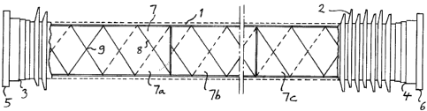
Fig 1 is a partially sectioned view illustrating a post insulator
according to the present invention,
Fig 2 is an enlarged sectioned view illustrating how adjacent
core sections and the inner wall of the tube of the post
insulator according to Fig 1 are arranged,
Fig 3 is a schematic view illustrating a step of the method for
manufacturing the post insulator according to the pres-
ent invention, and
Fig 4 is a perspective view of a post insulator according to
the invention standing on the ground.
DETAILED DESCRIPTION OF EN EMBODIMENT OF THE IN-
VENTION
Fig 1 shows schematically a post insulator according to the
present invention. This is made of a tube 1 of a fibre composite,
such as glass fibre epoxy, which here has a length of approxi-
mately six metres and an inner diameter of 31 cm and an outer
diameter of 33 cm. The tube 1 has an outer profile of rings 2 of
silicon rubber. The tube is at each end thereof provided with
flanges 3, 4 of aluminium adhesived to the ends of the tube.
Each end of the tube is provided with a flange cover 5, 6 having
an outer diameter of about 46 cm and enclosing the inner
volume of the tube.
CA 02632914 2008-06-10
WO 2007/073322 PCT/SE2006/050513
8
The inner volume of the tube is occupied by a core 7 of an in-
sulating material, such as foamed plastic.
The further structure of the post insulator will now be described
while simultaneously describing the method for manufacturing
the post insulator and making reference to all the figures. In this
manufacturing process one of the flange covers, such as the
flange cover 6, is initially not in place enabling introduction of
the core into the inner volume of the tube. The core is made of a
number of sections 7a, 7b, 7c having each a length of approxi-
mately 1 m. These sections have a cross-section with a diame-
ter slightly smaller than the inner diameter of the tube, such as
having a diameter being 2 mm less than the inner diameter of
the tube. A thin cord-like member 8 of for example glass fibre is
wound substantially helically around each core section before
introducing the core section into the tube. This is done with a
large pitch angle resulting in a pitch of for example 20 cm. The
cord-like member may then be cross-wound around the core, so
that once the core is introduced into the tube the cord-like mem-
ber will bear against the inner walls of the tube by cross-over
points 9 thereof. Thus, the cord-like member 8 forms a spacer
ensuring that a small circumferential space will separate the
core and the inner walls 10 of the tube. A further spacer 11 in
the form of a thin net is applied on the end of each core section
for obtaining a space between subsequent said core sections as
shown in Fig 2.
When the core sections are in place the flange cover 6 is at-
tached to the flange 4 by bolts and a device 21 for feeding
adhesive into the interior of the tube is connected to a first
opening 12 in said flange cover. The tube is then inclined with
respect to a horizontal while making an angle therewith of
approximately 45 . The flange cover 5 has a second opening 13
to the interior of the tube. Adhesive, such as a two-component
adhesive, is now introduced into the tube through said first
CA 02632914 2008-06-10
WO 2007/073322 PCT/SE2006/050513
9
opening 12 while allowing air to escape from the interior of the
tube through said second opening 13 on a higher level as said
adhesive is introduced. It is shown in Fig 3 how the two
openings are eccentrically arranged in the respective flange
cover, so that in the position according to Fig 3 the first opening
12 is arranged close to the lowest point of the flange cover 6,
while the second opening 13 is located close to the highest
point of the flange cover 5.
Air present in the spaces between the core sections and the
tube wall as well as between core sections will in this way be
pressed out of the tube through the second opening 13 when
these spaces are filled with adhesive. The second opening will
then be closed when no more air, but only adhesive is coming
out of this opening.
The introduction of adhesive into the tube is then continued
under overpressure until the pressure to be applied for intro-
ducing more adhesive into the tube exceeds a predetermined
level, which may correspond to an overpressure of 3.5 bars. The
connection between the device 21 and the first opening 12 is
then removed and this first opening 12 closed by screwing a
plug into an internal thread of this opening. The adhesive will
then cure while maintaining an overpressure in the interior of the
tube.
By the introduction of the adhesive into the tube with an over-
pressure a full compensation for possible shrinkage of the mate-
rials of the core and the tube is obtained, since both the core
sections and the tube will be elastically deformed by the over-
pressure. When the adhesive then shrinks during curing thereof
the overpressure is maintained by the "springback"-expansion
taking place by the core sections and the tube. Thus, compressi-
ve stresses will result in the adhesive joint, which are favourable
for the strength thereof.
CA 02632914 2008-06-10
WO 2007/073322 PCT/SE2006/050513
Thus, an homogenous unit with an excellent bounding of the
materials to each other is obtained.
Furthermore, this method results in a complete encapsulation of
5 the core, so that the material of the core may be selected so
that a cost efficient product is obtained.
The invention is of course not in any way restricted to the em-
bodiment described above, but many possibilities to modifica-
10 tions thereof will be apparent to a person with ordinary skill in
the art without departing from the basic idea of the invention as
defined in the appended claims.