Note: Descriptions are shown in the official language in which they were submitted.
CA 02633273 2008-06-13
T0463 UPA8-PCT-US/KAI
SEPARATOR OF FUEL CELL
BACKGROUND OF THE INVENTION
Field of the Invention
The present invention relates to a separator of a fuel cell. More
particularly, the present invention relates to a structure of a separator for
holding an MEA in which electrodes are provided on opposite sides of an
electrolyte.
Description of Related Art
As a separator to be applied to a fuel cell, there is known a structure
provided with streaked or linear fluid channels formed of a plurality of
convex
and concave portions arranged adjacent to one another in an undulated form,
and a distribution channel for distributing a reactant gas or cooling water to
be
introduced into these fluid channels (e.g., see Patent Document 1).
[Patent Document 1] Japanese Patent Application Laid-Open No.
2005-243651
SUMMARY OF THE INVENTION
However, in a separator having such a structure, there is a problem
that a differential pressure (a pressure loss) especially around a boundary
portion between a fluid channel and a distribution channel is large. When the
differential pressure around the boundary portion is thus large, problems
might
be caused with regard to ease of securing a seal property of a fluid and a
magnitude of a gas supply pressure (a supply capability).
1
CA 02633273 2008-06-13
T0463 UPA8-PCT-US/KAI
To solve the problems, an object of the present invention is to provide
a separator of a fuel cell having a structure capable of reducing a
differential
pressure in a boundary portion between streaked or linear fluid channels
formed
of a plurality of convex portions and concave portions arranged adjacent to
one
another in an undulated form and a distribution channel for distributing a
reactant gas or cooling water to be introduced into these fluid channels.
To solve such problems, the present inventor has performed various
investigations. In the investigations, the present inventor has noted a
conventional separator structure, especially a structure around a boundary
portion between the fluid channels formed in a streaked or linear form and the
distribution channel formed so as to come in contact with these fluid
channels,
and the inventor has found a technology capable of solving such a problem.
The present invention has been developed based on such a finding,
and a separator of a fuel cell which is formed so as to circulate a reactant
gas or
cooling water, comprising: streaked fluid channels formed of adjacent convex
and concave portions formed on the surface of the separator; and a
distribution
channel which distributes, to these fluid channels, a fluid to be introduced
toward the fluid channels, wherein a position of a terminal end of the convex
portion and a position of a terminal end of the concave portion constituting
the
fluid channels are displaced in a streak direction of the fluid channel.
The separator having the above-mentioned structure has a structure in
which the terminal end position of the convex portion (e.g., a convex rib) is
different from that of the concave portion (e.g., a concave groove), in other
words, a structure in which a so-called phase of a start end (or a dead end)
of
the convex portion is different from that of the start end of the concave
portion.
2
CA 02633273 2008-06-13
T0463 UPA8-PCT-US/KAI '
In this case, an area of an introducing portion, to a gas channel, of the
reactant
gas flowing, for example, from the distribution channel to the gas channel (or
an
area of the introducing portion, to a cooling water channel, of the cooling
water
flowing from the distribution channel to the cooling water channel) can be
enlarged. Therefore, as compared with a case where the terminal ends of the
convex and concave portions constituting the fluid channel are disposed on the
same line without any phase difference as in the conventional example, the
differential pressure in the boundary portion between the fluid channel and
the
distribution channel (the differential pressure which is exerted on the fluid,
also
referred to as a pressure loss) can be reduced. Therefore, the seal property
of
the fluid in the fluid channel is easily secured, and the supply pressure (the
supply capability) of the reactant gas or the cooling water does not have to
be
increased as in a conventional structure.
Moreover, in the separator of the fuel cell, a structure is preferable in
which the terminal end of the concave portion is positioned closer to the
distribution channel than the terminal end of the convex portion. In this
case, in
a surface provided with the concave and convex portions, the differential
pressure with respect to the fluid flowing on the surface is reduced
especially
around the boundary portion between the distribution channel and the fluid
channel.
Furthermore, it is preferable that the separator of the fuel cell has a
structure of such a type that front and back surfaces are integrated. In this
case,
for example, as described above, when the terminal end of the concave portion
is positioned closer to the distribution channel than the terminal end of the
convex portion, the back surface is provided with a reverse structure in the
back
3
CA 02633273 2008-06-13
T0463 UPA8-PCT-US/KAI
surface, that is, the terminal end of the convex portion is positioned closer
to the
distribution channel than the terminal end of the concave portion. In such a
structure, a way of the fluid flowing through the front surface can be varied
from
that of the fluid flowing through the back surface, so that flow speeds or
flow
rates of the fluids flowing through the front and back surfaces can be
controlled
by a separator structure.
Moreover, it is preferable that the distribution channel is provided with
a plurality of protrusions. These protrusions function so that the fluid (the
reactant gas or the cooling water) flowing through the distribution channel is
more equally distributed to the fluid channels. In addition, protrusions of
superimposed separators abut on each other, whereby the protrusions function
so as to support each other so that this distribution channel is not deformed.
Furthermore, the distribution channel may be one of a fluid return
portion, an introducing portion and a discharge portion.
Moreover, the separator of the fuel cell may be a metal separator.
BRIEF DESCRIPTION OF THE DRAWINGS
Fig. 1A is a plan view of a separator showing a structure example of
the separator according to a first embodiment of the present invention;
Fig. 1 B is a sectional view of the separator cut along the B-B line of Fig.
1 A;
Fig. 1 C is a sectional view of the separator cut along the C-C line of
Fig. 1A;
Fig. 2A is a plan view showing an enlarged structure around an
oxidizing gas inlet side manifold in the separator shown in Fig. 1A;
4
CA 02633273 2008-06-13
T0463 UPA8-PCT-US/KAI
Fig. 2B is a sectional view showing an enlarged structure around an
oxidizing gas inlet side manifold in the separator shown in Fig. 1 C;
Fig. 3A is a plan view showing a structure around terminal ends of a
convex rib and a concave groove in the first embodiment of the present
invention;
Fig. 3B is a sectional view cut along the B-B line of Fig. 3A;
Fig. 3C is a sectional view cut along the B-B line of Fig. 3A and
showing an area of a traverse section of a gas introducing portion;
Fig. 3D is a sectional view cut along the D-D line of Fig. 3A;
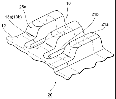
Fig. 4 is a perspective view showing a structure around the terminal
ends of the convex rib and the concave groove in the first embodiment of the
present invention;
Fig. 5A is a plan view showing a structure around terminal ends of a
convex rib and a concave groove in a second embodiment of the present
invention;
Fig. 5B is a sectional view cut along the C-C line of Fig. 5A;
Fig. 6 is a plan view showing a structure example of a separator in a
third embodiment of the present invention;
Fig. 7 is a diagram showing an enlarged structure around an oxidizing
gas inlet side manifold in the separator shown in Fig. 6;
Fig. 8 is a plan view showing a structure example of a separator in a
fourth embodiment of the present invention;
Fig. 9 is a diagram showing an enlarged structure around an oxidizing
gas inlet side manifold in the separator shown in Fig. 8;
Fig. 10 is a sectional view showing a structure example of a linear
5
CA 02633273 2008-06-13
T0463 UPA8-PCT-US/KAI
channel portion in a case where an MEA and a separator are laminated;
Fig. 11 is a sectional view showing a structure example of a
distribution channel portion in a case where the MEA and the separator are
laminated; and
Fig. 12 is a perspective view showing an exploded unitary cell of a fuel
cell according to the embodiments of the present invention.
DETAILED DESCRIPTION OF PREFERRED EMBODIMENT
A preferable mode for carrying out the present invention will be
described with reference to the drawings. The following embodiments illustrate
the present invention, and the present invention is not limited to the
following
embodiments and can variously be modified and implemented.
Fig. 1A to Fig. 12 show embodiments of a separator of a fuel cell
according to the present invention. This separator 20 holds a membrane
electrode assembly (MEA) 30 in which electrodes 32a, 32b are provided on
opposite sides of an electrolytic film (a polymer electrolytic film) 31, to
constitute
a fuel cell 1, and has a structure provided with a linear fluid channel which
is
constituted of a convex portion (a convex rib) 21 a including a linear rib and
a
concave portion (a concave groove) 21 b including a groove and which supplies
a fluid, and a distribution channel 12 constituted of a flat surface
positioned at a
height between the convex portion 21a and a concave portion 21b. The
following embodiments are characterized in that a position of a terminal end
of
the convex portion 21a is different from that of a terminal end of the concave
portion 21b with respect to a line vertical to a flow direction of the linear
fluid
channel in a boundary portion between the linear fluid channel and the
6
CA 02633273 2010-06-02
distribution channel 12 in the separator 20 of this fuel cell 1.
In the following embodiments, first a schematic constitution of a stack
3 constituting the fuel cell 1 will be described, and then a structure of the
separator 20 will be described in detail (see Fig. 12, etc.). It is to be
noted it is
the separator 20 of the fuel cell 1 described in the present embodiment is
provided with the fluid channel of a straight type or a serpentine type, and a
fluid
inlet or a fluid outlet of these fluid channels is provided with the
distribution
channel (a distributing portion) 12 for distributing a fluid to a plurality of
fluid
channels.
Fig. 12 shows a schematic constitution of a cell 2 of the fuel cell 1 in
the present embodiment. It is to be noted that the fuel cell 1 constituted by
laminating these cells 2 is usable as a vehicle-mounted power generation
system of, for example, a fuel cell hybrid vehicle (FCHV), but the fuel cell
is not
limited to this example, and the fuel cell may be used as a power generation
system or the like to be mounted on a self-propelled body such as any type of
mobile body (e.g., a ship, an airplane or the like) or a robot.
The cell 2 is constituted of the MEA 30 and a pair of separators
(denoted with reference numerals 20a, 20b in Fig. 12) which hold the MEA 30
therebetween (see Fig. 12). The MEA 30 and the separators 20a, 20b are
substantially formed into a rectangular plate-like shape. Moreover, an outer
shape of the MEA 30 is formed to be slightly smaller than outer shapes of the
separators 20a, 20b. Furthermore, portions around the MEA 30 and the
separators 20a, 20b are molded of a molding resin together with a first seal
member 50a and a second seal member 50b.
The MEA 30 is constituted of the polymer electrolytic film (hereinafter
7
CA 02633273 2008-06-13
T0463 UPA8-PCT-US/KAI
also referred to simply as the electrolytic film) 31 including an ion exchange
film
of a polymer material, and a pair of electrodes 32a, 32b (an anode and a
cathode) which hold both surfaces of the electrolytic film 31. Among these
components, the electrolytic film 31 is formed to be slightly larger than the
electrodes 32a, 32b. This electrolytic film 31 is bonded to the electrodes
32a,
32b by, for example, a hot press process in a state in which a peripheral edge
portion 33 is left.
The electrodes 32a, 32b constituting the MEA 30 are constituted of, for
example, a porous carbon material (a diffusion layer) which carries a catalyst
10, such as platinum attached to the surface of the material. A hydrogen gas
is
supplied as a fuel gas to one electrode (the anode) 32a, and an oxidizing gas
such as air or an oxidizing agent is supplied to the other electrode (the
cathode)
32b. These two types of gases cause an electrochemical reaction in the MEA
30, to obtain an electromotive force of the cell 2.
The separators 20a, 20b are constituted of a conductive material which
is impermeable to the gas. Examples of the conductive material include carbon,
a hard resin having conductivity, and a metal such as aluminum or stainless
steel. A base of the separators 20a, 20b of the present embodiment is formed
of a plate-like metal (metal separators), and surfaces of this base on
electrodes
32a, 32b sides are provided with films (e.g., membranes plated with gold)
having excellent resistance to corrosion.
Moreover, both the surfaces of the separators 20a, 20b are provided
with groove-like channels constituted of a plurality of concave portions. In a
case where the base of the separators 20a, 20b of the present embodiment is
made of, for example, the plate-like metal, these channels can be formed by
8
CA 02633273 2008-06-13
T0463 UPA8-PCT-US/KAI
press forming. The groove-like channels formed in this manner constitute a gas
channel 34 of the oxidizing gas, a gas channel 35 of the hydrogen gas and a
cooling water channel 36. More specifically, a plurality of gas channels 35 of
the hydrogen gas are formed in an inner surface of the separator 20a on the
electrode 32a side, and a plurality of cooling water channels 36 are formed in
a
back surface (an outer surface) of the separator (see Fig. 12). Similarly, a
plurality of gas channels 34 of the oxidizing gas are formed in an inner
surface
of the separator 20b on the electrode 32b side, and a plurality of cooling
water
channels 36 are formed in a back surface (an outer surface) of the separator
(see Fig. 12). For example, in the present embodiment, these gas channels 34
and the gas channels 35 are formed in parallel with each other in the cell 2.
Furthermore, in the present embodiment, in a case where two cells 2,2 are
arranged adjacent to each other so that the outer surface of the separator 20a
of the one cell 2 is attached to the outer surface of the separator 20b of the
adjacent cell 2, the cooling water channels 36 of both the cells are
integrated to
form a channel having, for example, a rectangular section (see Fig. 10, Fig.
12).
It is to be noted that a peripheral portion between the separator 20a and the
separator 20b of the adjacent cells 2, 2 is molded of a molding resin.
Moreover, around an end of the separator 20a or 20b in a longitudinal
direction (in the vicinity of one end shown on the left in Fig. 12 as one
faces, in
the present embodiment), a manifold 15a of the oxidizing gas on an inlet side,
a
manifold 16b of the hydrogen gas on an outlet side, and a manifold 17b of
cooling water (denoted with a symbol C in Fig. 12) on the outlet side are
formed.
For example, in the present embodiment, these manifolds 15a, 16b and 17b are
formed of substantially rectangular or trapezoidal through holes provided in
the
9
CA 02633273 2008-06-13
T0463 UPA8-PCT-US/KAI
separators 20a, 20b (see Fig. 6, Fig. s12). Furthermore, an opposite end of
the
separator 20a or 20b is provided with a manifold 15b of the oxidizing gas on
the
outlet side, a manifold 16a of the hydrogen gas on the inlet side, and a
manifold
17a of the cooling water on the inlet side. In the present embodiment, these
manifolds 15b, 16a and 17a are also formed of substantially rectangular or
trapezoidal through holes (see Fig. 6, Fig. 12).
Among the above-mentioned manifolds, the inlet manifold 16a and the
outlet manifold 16b for the hydrogen gas in the separator 20a are connected to
the gas channels 35 of the hydrogen gas via an inlet communication passage
61 and an outlet communication passage 62 formed in a groove-like shape in
the separator 20a, respectively. Similarly, the inlet manifold 15a and the
outlet
manifold 15b for the oxidizing gas in the separator 20b are connected to the
gas
channels 34 of the oxidizing gas via an inlet communication passage 63 and an
outlet communication passage 64 formed in a groove-like shape in the
separator 20b, respectively (see Fig. 12). Furthermore, the inlet manifold 17a
and the outlet manifold 17b for the cooling water in the separator 20a or 20b
are
connected to the cooling water channels 36 via an inlet communication passage
65 and an outlet communication passage 66 formed in a groove-like shape in
the separator 20a or 20b, respectively. According to the constitution of the
separators 20a, 20b described above, the oxidizing gas, the hydrogen gas and
the cooling water are supplied to the cell 2. Here, a specific example will be
described. For example, the hydrogen gas passes through the communication
passage 61 from the inlet manifold 16a of the separator 20a to flow into the
gas
channel 35 for use in power generation of the MEA 30. Afterward, the hydrogen
gas passes through the communication passage 62, and is discharged to the
CA 02633273 2010-06-02
outlet manifold 16b.
Both of the first seal member 50a and the second seal member 50b
are members having a frame-like shape and formed into substantially the same
shape (see Fig. 12). In these members, the first seal member 50a is provided
between the MEA 30 and the separator 20a, and more specifically interposed
between the peripheral edge portion 33 of the electrolytic film 31 and a
portion
of the separator 20a around the gas channel 35. The second seal member 50b
is provided between the MEA 30 and the separator 20b, and more specifically
interposed between the peripheral edge portion 33 of the electrolytic film 31
and
a portion of the separator 20b around the gas channel 34.
Furthermore, a frame-like third seal member 50c is provided between
the separator 20b and the separator 20a of the adjacent cells 2, 2 (see Fig.
12).
This third seal member 50c is a member provided so as to be interposed
between a portion of the separator 20b around the cooling water channel 36
and a portion of the separator 20a around the cooling water channel 36,
thereby
sealing between these portions. Incidentally, in the cell 2 of the present
embodiment, among various passages (34 to 36, 15a, 15b, 16a, 16b, 17a, 17b
and 61 to 66) of the fluids in the separators 20a, 20b, the inlet manifolds
15a,
16a and 17a and the outlet manifolds 15b, 16b and 17b of various fluids are
passages positioned outside the first seal member 50a, the second seal
member 50b and the third seal member 50c (see Fig. 12).
Next, a structure of the separator in the present embodiment (denoted
with the reference numerals 20a, 20b in the above description, but sometimes
simply denoted with reference numeral 20 in the following description) will be
described in detail (see Fig. 1A, etc.). The separator 20 is provided with a
fluid
11
CA 02633273 2008-06-13
T0463 UPA8-PCT-US/KAI
channel of a straight or serpentine type, and inlets and outlets of a
plurality of
channels are further provided with distribution channels (distributing
portions)
12 for distributing the fluid to the fluid channels. A linear portion (this is
also
referred to as a linear channel in the present specification) of the fluid
channel is
constituted of linear convex portion 21a and concave portion 21b, and the
distribution channel 12 is constituted of a flat surface at a position lower
than
the convex portion 21 a and higher than the concave portion 21 b. For example,
in the present embodiment, the convex portion 21 a is constituted of a rib
having
a protruding shape (hereinafter referred to as the "convex rib", and this is
denoted with reference numeral 21a), and the concave portion 21b is
constituted of a groove having a recessed shape (hereinafter referred to as
the
"concave groove ", and this is denoted with reference numeral 21 b). It is to
be
noted that one separator 20 is formed so that a section of the separator has
an
undulated form. A back surface of the convex rib 21 a is provided with the
concave groove 21 b, and a back surface of the concave groove 21 b is provided
with the convex rib 21 a so that front and back surfaces are integrally formed
(see Fig. 10). Moreover, the fluid mentioned herein is, for example, the
cooling
water in the surface where the separators 20 face each other, and the fluid is
a
reactant gas such as the oxidizing gas or the fuel gas in the surface where
the
separator 20 faces the MEA 30. It is to be noted that in the present
specification, it is described that the gas channel or the cooling water
channel
36 constituted of the convex rib 21 a and the concave groove 21 b is linear,
but
the linear form mentioned herein is not a straight form only. In short, it is
meant
that the plurality of fluid channels are formed to be adjacent to one another,
thereby forming a so-called streaked form. Moreover, the gas channel
12
CA 02633273 2008-06-13
T0463 UPA8-PCT-US/KAI
mentioned herein is the gas channel 34 of the oxidizing gas or the gas channel
35 of the hydrogen gas, that is, a channel of the reactant gas, and the
channel
is denoted with reference numeral 10 in Fig. 2A and the like.
Furthermore, the above separator 20 is characterized in a structure in
which a position of a terminal end of the convex rib 21 a is different from
that of
a terminal end of the concave groove 21 b with respect to a line vertical to a
flow
direction of the linear channel in a boundary portion between these linear
channels and the distribution channel 12. In other words, a structure is
characteristic in which with regard to a plurality of convex portions 21a and
concave portions 21b repeatedly formed adjacent to one another so as to form
the gas channel 10, phases of the terminal ends of the convex portions 21 a
and
the terminal ends of the concave portions 21b are successively displaced.
First
to fourth embodiments of such a structure of the separator 20 will hereinafter
separately be described.
<First Embodiment>
First, Fig. 1A to Fig. 1C show a separator 20 provided with a straight
type gas channel 10. As described above, ends of this separator 20 are
provided with inlet manifolds 15a, 16a and 17a and outlet manifolds 15b, 16b
and 17b of various fluids (an oxidizing gas, a fuel gas and cooling water).
Moreover, both ends of the gas channel 10 are provided with distribution
channels 12 for distributing a gas to the gas channels 10 (see Fig. 1A, Fig.
2A,
etc.). It is to be noted that a portion where the gas discharged from the gas
channel 10 joins will also be referred to as the distribution channel 12 in
the
present embodiment. That is, in this case, the distribution channel 12 does
not
substantially distribute the gas, but has a symmetric structure, and the gas
can
13
CA 02633273 2008-06-13
T0463 UPA8-PCT-US/KAI
be supplied in either direction. Therefore, in the present embodiment, both
the
portions are referred to as the "distribution channels" for the sake of
convenience.
This distribution channel 12 is provided with a plurality of protrusions
23a formed during, for example, press molding, and other protrusions 24a
raised on a side opposite to the protrusions 23a (see Fig. 1A, Fig. 2A, etc.).
Among these protrusions, the protrusions 23a protrude on the same side (e.g.,
a front surface side) as the convex ribs 21 a, and are formed so as to have a
height H1 equal to a height of this convex rib 21a (see Fig. 2A to Fig. 2C).
This
protrusion 23a collides with the surface of an MEA 30 to secure a region for
supplying the gas between the MEA 30 and the separator 20 (see Fig. 11).
Moreover, the protrusions 24a protrude on the same side (e.g., a back surface
side) as a recessed side of the concave grooves 21 b, and are formed so as to
have a height H2 equal to a height of the convex rib 21 a formed on the back
surface of this concave groove 21 b so that front and back surfaces are
integrated (see Fig. 2A to Fig. 2C). This protrusion 24a collides to the
protrusion 24a of the adjacent separator 20 to secure a region (a cooling
water
channel 36) for supplying the cooling water between two separators 20 (see
Fig.
11). It is to be noted that it is preferable to arrange these protrusions 23a,
24a
with equal intervals as in the present embodiment from a viewpoint that
regions
for supplying various gases or the cooling water are held with equal intervals
to
achieve constant ease of flowing (see Fig. 1A, etc.). Moreover, back surfaces
of the protrusions 23a, 24a are provided with dimples 23b, 24b simultaneously
formed during, for example, press molding, respectively (see Fig. 11, etc.).
It is
to be noted that reference numerals 40, 41 in Fig. 11 are insulating members,
14
CA 02633273 2008-06-13
T0463 UPA8-PCT-US/KAI
respectively.
The convex rib 21 a and the concave groove 21b have a structure in
which positions of portions as terminal ends are different from each other in
a
back-and-forth direction in a boundary portion between a linear channel and
the
distribution channel 12 (see Fig. 4). One example of such a structure will
specifically be described as follows, while lengths of portions are denoted
with
symbols.
That is, in the separator 20 having a total length LO in a longitudinal
direction and a total width WO, in the present embodiment, a total length of
the
convex rib 21 a is L1, whereas a total length of the concave groove 21 b is L2
longer than the total length of the rib (L2 > L1) in a structure in which a
terminal
end of the concave groove 21b is positioned closer to the distribution channel
12 than a terminal end of the convex rib 21 a (see Fig. 1 A to Fig. 1 C).'
Here, the
convex rib 21 a and the concave groove 21b shown in the present embodiment
are symmetrically formed with respect to the center line as a reference, so
that
eventually, the concave groove 21 b in one end of the separator 20 is formed
to
be longer than the convex portion 21 a as much as SAX1 = (L2-L1)/2 (see Fig.
2A to Fig. 3D).
Moreover, a structure around the terminal ends of the convex rib 21 a
and the concave groove 21b in the present embodiment will be described in
more detail (see Fig. 2A to Fig. 4). First, the terminal end portion of the
convex
rib 21 a is provided with a tilt portion (denoted with 25a in Fig. 4) having a
length
S3 in the longitudinal direction (see Fig. 3A to 4). As apparent from Fig. 3A
to
Fig. 3D, a total length portion of the convex rib 21a having the length L1
does
not include this tilt portion 25a. Moreover, the terminal end portion of the
CA 02633273 2008-06-13
T0463 UPA8-PCT-US/KAI
concave groove 21 b is provided with a tilt portion (denoted with 25b in Fig.
3A,
Fig. 3D). As apparent from Fig. 3A and the like, this tilt portion 25b is
included
in a total length of the concave groove 21 b having the length L2. It is to be
noted that symbol S2 shown in Fig. 3D is a length obtained by subtracting the
length of the tilt portion 25b in the terminal end portion of the concave
groove
21 b from a differential length (= SAX1 described above) between the terminal
end position of the concave groove 21 b and the terminal end position of the
convex rib 21 a.
It is to be noted that, in addition, a total thickness of the separator 20 is
denoted with a symbol HO (see Fig. 3B, Fig. 3D). This thickness HO is a value
(HO = tO+H1 +H2) obtained by adding up a plate thickness tO of a plate
material
constituting the separator 20, the protruding height H1 of the above-mentioned
convex rib 21a and the protrusion 23a and the protruding height H2 of the
above-mentioned back surface convex rib 21 a and the protrusion 24a.
Furthermore, a space between the convex rib 21 a and the adjacent convex rib
21 a (or a space between the concave groove 21 b and the adjacent concave
groove 21 b) is denoted with a symbol Pm (see Fig. 3B).
In the separator 20 having the above-mentioned structure, a total
length L2 of the concave groove 21 b is set to be longer than a total length
L1 of
the convex rib 21 a, whereby a gas introducing portion 13a is formed (see Fig.
4).
In such a case, a gas flowing through the distribution channel 12 is easily
introduced into the gas channel (the linear channel) 10 through this gas
introducing portion 13a, so that a differential pressure (the differential
pressure
exerted to a fluid, and this may be referred to as the "pressure loss") in a
boundary portion between the distribution channel 12 and the linear channel is
16
CA 02633273 2008-06-13
T0463 UPA8-PCT-US/KAI
reduced. In addition, the "pressure loss" indicates that energy such as the
pressure of the fluid is consumed owing to a shape of the fluid channel,
smoothness of the surface of the fluid channel or the like.
It is to be noted that in the present embodiment, an extended portion of
the gas channel 10 formed in a terminal end of the concave groove 21b is
referred to as the gas introducing portion 13a only for the sake of
convenience.
For example, in a case where the gas in the gas channel 10 flows in reverse,
the gas is discharged from the gas introducing portion 13a. In this case, this
portion is exactly referred to as the "gas discharge portion", depending on a
direction of the flow of the gas. In short, according to the separator 20 of
the
present embodiment, the differential pressure in the boundary portion between
the linear channel and the distribution channel 12 can be suppressed and
reduced regardless of whether the portion is the introducing portion or the
discharge portion of the gas.
Moreover, the gas-side protruding height H1 and the cooling-water-
side protruding height H2 in the separator 20 having the above-mentioned
structure can be set to various values with reference to proportionally
distributed
dimensions of the reactant gas and the cooling water in the distribution
channel
12 (i.e., dimensions in a case where quantities are distributed at a ratio
proportional to a reference quantity), but in the present embodiment, the
heights
are set so as to satisfy the following relation between both the heights (see
Fig.
3B, Fig. 3D).
[Formula 1 ]
H1 > H2
That is, the separator 20 shown in Fig. 3B and the like has a structure in
which
17
CA 02633273 2008-06-13
T0463 UPA8-PCT-US/KAI
the gas-side protruding height H1 is larger than the cooling-water-side
protruding height H2. In this case, the differential pressure in the boundary
portion between the linear channel and the distribution channel 12 can
preferably be suppressed and further reduced.
Moreover, it has been described with reference to Fig. 2A to Fig. 3D
that the concave groove 21 b in one end of the separator 20 is formed so as to
be longer than the convex portion 21 a as much as SAX1 = (L2-L1)/2. However,
from a viewpoint that the differential pressure in the boundary portion
between
the linear channel and the distribution channel 12 is further reduced, this
SAX1
is preferably set to a value larger than a constant value. One example of the
present embodiment is as follows.
[Formula 2]
SAX1 > 3-t0
That is, a magnitude (a length) of SAX1 is set to a value three or more times
the
plate thickness t0 of the separator 20, whereby the gas introducing portion
13a
having a predetermined length (or a predetermined area) or more is secured in
the separator 20 having a plate thickness t0. In such a case, the differential
pressure in the boundary portion between the linear channel and the
distribution
channel 12 can effectively be reduced to a certain degree or less. In
addition, in
a case where a dimension between the held MEAs 30 is reduced, in other
words, in a case where the total thickness HO of the separator 20 is reduced,
when SAX1 is set as described above, the separator 20 can effectively be
minimized while reducing the differential pressure.
Furthermore, the following setting is preferable. That is, a structure
preferably satisfies the following relations:
18
CA 02633273 2008-06-13
T0463 UPA8-PCT-US/KAI
[Formula 3]
A2/A1 > 0.4; and
[Formula 4]
A3>A2,
in which A3 is an area of a portion (i.e., a portion showing a vertical
section of
the gas introducing portion 13a) shown by a one-dot chain line in Fig. 3D, A2
is
an area of a portion (i.e., a portion showing a sectional area of the concave
groove 21 b) shown by a one-dot chain line in Fig. 3C, and Al is an area of a
portion (i.e., a portion showing a transverse section of the gas introducing
portion 13a) shown by a one-dot chain line in Fig. 3B. In this case,
similarly, the
differential pressure in the boundary portion between the linear channel and
the
distribution channel 12 can be reduced to a certain degree or less. It is to
be
noted that in this case, the total length L2 of the concave groove 21b is
longer
(L2 > L1) is longer than the total length Ll of the convex rib 21 a in the
same
manner as described above.
It is to be noted that a configuration for reducing the differential
pressure has been described in accordance with an example in which the
oxidizing gas or the fuel gas is introduced into the gas channel 10, but
conversely, a structure for reducing the differential pressure can be provided
in
a case where the cooling water is introduced from the distribution channel 12
to
the linear channel. This structure will hereinafter be described as a second
embodiment.
<Second Embodiment>
Fig. 5A to Fig. 5C show one example of a structure for reducing a
differential pressure in a case where cooling water is introduced from a
19
CA 02633273 2008-06-13
T0463 UPA8-PCT-US/KAI
distribution channel 12 to a linear channel. Contrary to the separator shown
in
Fig. 3A and the like, this separator 20 satisfies a relation L1 > L2. That is,
a
total length L2 of a concave groove 21b is shorter than a total length L1 of a
convex rib 21 a, and a terminal end of the convex rib 21 a is positioned
closer to
the distribution channel 12 than a terminal end of the concave groove 21 b
(see
Fig. 5A to Fig. 5C). Here, the convex rib 21 a and the concave groove 21 b are
formed symmetrically with respect to center lines, respectively, and hence
eventually, the convex rib 21 a in one end of the separator 20 of the present
embodiment is formed to be longer than the concave groove 21b as much as
SBX1 = (1-1 -L2)/2 (see Fig. 5A, etc.).
Moreover, a structure around the terminals of the convex rib 21a and
the concave groove 21b in the present embodiment will be described in more
detail (see Fig. 5A, etc.). First, a terminal end portion of the convex rib 21
a is
provided with a tilt portion 25a having a length S4 in a longitudinal
direction (see
Fig. 5A, etc.). As apparent from Fig. 5A and the like, a total length portion
of the
convex rib 21a having the length L1 does not include this tilt portion 25a.
Moreover, a terminal end portion of the concave groove 21b is also provided
with a tilt portion (denoted with symbol 25b in Fig. 5A, Fig. 5C). As apparent
from Fig. 5A and the like, this tilt portion 25b is included in the total
length L2 of
the concave groove 21 b. It is to be noted that symbol S5 in Fig. 5C is a
length
obtained by adding the length of the tilt portion 25b in the terminal end
portion of
the concave groove 21b to a differential length (= SAX1 described above)
between a terminal end position of the convex rib 21a and a terminal end
position of the concave groove 21 b.
Furthermore, the separator 20 has a total thickness HO in the same
CA 02633273 2008-06-13
T0463 UPA8-PCT-US/KAI
manner as in the above-mentioned embodiment (see Fig. 513, Fig. 5C). This
thickness HO is a value (HO = tO+H1+H2) obtained by adding up a plate
thickness tO of a plate material constituting the separator 20, a protruding
height
H1 of the above-mentioned convex rib 21a and a protruding height H2 of the
concave groove 21b on the side of a back surface. Furthermore, a space
between the convex rib 21a and the adjacent convex rib 21a (or a space
between the concave groove 21b and the adjacent concave groove 21b) is
denoted with a symbol Pm (see Fig. 5B).
The separator 20 having the above-mentioned structure has an
advantage that a gas introducing portion 13a having a broad introduction
region
as described above is not formed as viewed from a side provided with a gas
channel 10, but a reverse structure is provided as viewed from the back
surface
of the gas channel 10, that is, as viewed from the surface on the side of a
cooling water channel 36. That is, on the side of the cooling water, a so-
called
cooling water introducing portion (denoted with symbol 14a in Fig. 5C) is
formed
in the same manner as in the gas introducing portion 13a of the first
embodiment described above. Therefore, a differential pressure in a boundary
portion between a linear channel and the distribution channel 12 on the side
of
the cooling water can be suppressed and reduced.
It is to be noted that the gas-side protruding height H1 and the cooling-
water-side protruding height H2 in the separator 20 having the above-
mentioned structure can be set to various values with reference to
proportionally distributed dimensions of a gas and the cooling water in the
distribution channel 12, but in the present embodiment, the heights are set so
as to satisfy the following relation between both the heights (see Fig. 5C).
21
CA 02633273 2008-06-13
T0463 UPA8-PCT-US/KAI
[Formula 5]
H1 >H2
That is, in the separator 20 shown in Fig. 5C and the like, the gas-side
protruding height H1 is larger than the cooling-water-side protruding height
H2.
In consequence, the differential pressure in the boundary portion between the
linear channel and the distribution channel 12 can be suppressed and further
reduced.
Moreover, the following setting is preferable. That is, a structure
preferably satisfies the following relations:
[Formula 6]
A5/A4 > 0.2; and
[Formula 7]
A6 > A5,
in which A6 is an area of a portion (i.e., a portion showing a vertical
section of
the cooling water introducing portion 14a) shown by a one-dot chain line in
Fig.
5C), A5 is an area of a portion (i.e., a portion showing a transverse section
of
the cooling water introducing portion 14a) shown by a one-dot chain line in
Fig.
5B, and A4 is an area of a portion (i.e., a portion showing a transverse
section
of the cooling water channel 36) shown by a two-dot chain line in Fig. 5B. In
this case, similarly, the differential pressure in the boundary portion
between the
linear channel (the cooling water channel 36) of the cooling water and the
distribution channel 12 can be reduced to a certain degree or less. It is to
be
noted that in this case, the total length L1 of the convex rib 21 a is longer
(L1 >
L2) is longer than the total length L2 of the concave groove 21 b in the same
manner as described above.
22
CA 02633273 2008-06-13
T0463 UPA8-PCT-US/KAI
It is to be noted that in the above-mentioned first and second
embodiments, a structure is provided in which one of the total length L1 of
the
convex rib 21 a and the total length L2 of the concave groove 21 b is
lengthened,
and the other length is shortened (see Fig. 1A, etc.), but this is merely one
example, an a configuration in which a terminal end position of the convex rib
21a is different from that of the concave groove 21b is not limited to this
example. Another example will be described. In a structure, while the total
length L1 of the convex rib 21a is equal to the total length L2 of the concave
groove 21b, one position (the convex rib 21a) may relatively be displaced from
the other position (the concave groove 21b) in a channel direction. In such a
case, the one end of a front surface can be provided with the gas introducing
portion 13a, and the other end of a back surface can be provided with the
cooling water introducing portion 14a, so that a flow direction of the gas (an
oxidizing gas or a fuel gas) and a flow direction of the cooling water may be
varied in the front and back surfaces, and the differential pressures of the
gas
and the cooling water can be reduced.
<Third Embodiment>
Next, a case where the present invention is applied to a separator 20
having serpentine type channels will be described (see Fig. 6, Fig. 7).
Fig. 6 and Fig. 7 show one example of the serpentine type separator
20 viewed from the side of a gas (an oxidizing gas or a fuel gas) channel 10.
Ends of this separator 20 are provided with inlet manifolds 15a, 16a and 17a
and outlet manifolds 15b, 16b and 17b of various fluids (the oxidizing gas,
the
fuel gas and cooling water) in the same manner as in the above embodiments
(see Fig. 6). In the separator 20 of the present embodiment, distribution
23
CA 02633273 2008-06-13
T0463 UPA8-PCT-US/KAI
channels 12 of the gases are provided in the vicinities of the inlet manifolds
15a,
16a and 17a and the outlet manifolds 15b, 16b and 17b of various fluids (the
oxidizing gas, the fuel gas and the cooling water), respectively, and a
plurality of
straight gas channels 10 (and cooling water channels 36) constituted of a
plurality of parallel convex ribs 21 a and concave grooves 21 b are provided
between these distribution channels 12 provided on these opposite ends (see
Fig. 6). In the distribution channel 12, protrusions 23a which protrude toward
a
surface provided with the gas channel 10 and dimples 24b formed on back
surfaces of protrusions 24a which protrude toward a surface provided with the
cooling water channel 36 are alternately arranged (see Fig. 6, Fig. 7).
Moreover,
in the distribution channel 12 and the straight type gas channel 10, two rows
of
gas block convex portions 18 parallel to the gas channels 10 are provided in a
mutually offset state, whereby a serpentine type channel having two return
portions 19 are formed (see Fig. 6). A convex portion 22a and a concave
portion 22b alternately formed along an extension of the formed rib-like gas
block convex portion 18 toward the return portion 19, whereby the gas (the
oxidizing gas or the fuel gas) flows through the convex portion 22a and a gap
between the convex portions 22a or a plurality of arranged convex portions 22a
along the extensions (see Fig. 6). The plurality of gas channels 10 on a back
surface side are provided with the cooling water channels 36 (with the proviso
that the cooling water channels are omitted from Fig. 6 and Fig. 7), and gas
inlet
and outlet of the gas channel 10 and cooling water inlet and outlet of the
cooling
water channel 36 are provided with the distribution channels 12, respectively.
Even in such a serpentine type separator 20, according to the present
embodiment, a boundary portion between the gas channel 10 (and the cooling
24
CA 02633273 2008-06-13
T0463 UPA8-PCT-US/KAI
water channel 36) and the distribution channel 12 has a structure in which a
terminal end position of the convex portion 21 a is displaced from that of the
concave portion 21b. That is, the position of a terminal end of the convex rib
21a is different from that of the terminal end of the concave groove 21b with
respect to a line vertical to a flow direction of a fluid channel (the gas
channel
and the cooling water channel 36) (see Fig. 7, etc.).
Here, in the same manner as in the first embodiment, the present
embodiment has a structure in which a total length (L2) of the concave groove
21b is longer than a total length (L1) of the convex rib 21 a. Moreover, a gas
10 inlet portion to the concave groove 21 b is provided with a gas introducing
portion 13a, and a gas outlet portion is provided with a gas discharge portion
13b, respectively (see Fig. 7, etc.). In such a case, the gas flowing through
the
distribution channel 12 is easily introduced into the gas channel 10 through
this
gas introducing portion 13a, so that a differential pressure in the boundary
portion between the distribution channel 12 and the gas channel 10 is reduced.
Moreover, shapes and structures of the convex rib 21 a and the concave groove
21 b are provided with so-called phases in this manner, whereby stepped
concave and convex portions are reduced to about a half especially in rising
portions (in other words, portions around the gas introducing portion 13a and
the gas discharge portion 13b) of the convex rib 21 a and the concave groove
21 b. As a result, a molding property of the separator 20 improves in the same
manner as in the above embodiments.
<Fourth Embodiment>
A configuration has been described in a case where the serpentine
type separator 20 is provided with the introducing portion 13a of the gas (the
CA 02633273 2008-06-13
T0463 UPA8-PCT-US/KAI
hydrogen gas or the fuel gas) or the gas discharge portion 13b, but the same
serpentine type separator 20 may be provided with a cooling water introducing
portion 14a and the like. That is, in the same manner as in, for example, the
second embodiment described above, a structure can be provided in which a
total length L2 of a concave groove 21b is shorter than a total length L1 of a
convex rib 21 a, and a terminal end of the convex rib 21 a is positioned
closer to
the distribution channel 12 than a terminal end of the concave groove 21b (see
Fig. 8, Fig. 9). This separator 20 has an advantage that the gas introducing
portion 13a having a large introduction region is not formed as viewed from a
side provided with a gas channel 10 (see Fig. 9, etc.), but a reverse
structure is
provided as viewed from a back surface of the gas channel 10, that is, the
surface of a cooling water channel 36. That is, on a cooling water side, a
cooling water introducing portion (denoted with symbol 14a in, for example,
Fig.
5C) similar to the gas introducing portion 13a described in the above
embodiment is formed. Therefore, according to the separator 20 having such a
structure, a differential pressure in a boundary portion between a linear
channel
and a distribution channel 12 on the cooling water side can be suppressed and
reduced.
With regard to the separator 20 constituting the fuel cell 1, various
embodiments of the structure in which the terminal end position of the convex
rib 21a is displaced from that of the adjacent concave groove 21 b have been
described. According to the above-mentioned separator 20, in any embodiment,
the gas or the cooling water is easily introduced into the linear channel
through
the gas introducing portion 13a or the cooling water introducing portion 14a,
so
that the effect that the differential pressure in the boundary portion between
the
26
CA 02633273 2008-06-13
T0463 UPA8-PCT-US/KAI
distribution channel 12 and the linear channel can be reduced is obtained.
In addition, according to the separators 20 described above, not only
the differential pressure reduction effect but also the effect that the
molding
property of the separator 20 improves are obtained. That is, in a conventional
structure, the terminal end positions of the convex rib and the concave groove
are aligned, so that the stepped concave and convex portions are large in the
terminal end positions. Therefore, during molding, a material is not
completely
supplied around the terminal end position, whereby creases are sometimes
increased. Therefore, a high precision is demanded during the molding, and
cost sometimes increases. On the other hand, in the present embodiment
having the structure in which the terminal end position is displaced, the
stepped
concave and convex portions in the terminal end positions of the convex rib 21
a
and the concave groove 21b are suppressed, so that the material is easily
supplied as compared with the conventional structure. Therefore, there are
advantages that any crease is not easily generated and that any crack around
the terminal end positions is not easily generated. As a result, during the
molding, unlike the conventional structure, a strict precision is not
required, and
an effect that the molding property of the separator 20 improves
Such an effect that the molding property improves or an effect due to
this effect will hereinafter be described in more detail.
That is, first, a structure of a conventional separator has a plurality of
gas grooves each including a flat peripheral portion and the center
constituted
of concave and convex portions. In a groove end, tilt angles of the concave
and
convex portions are set so that a difference between a blunt angle and an
acute
angle is made for every other groove or four grooves. While the gas is
returned
27
CA 02633273 2008-06-13
T0463 UPA8-PCT-US/KAI
using a space formed in a gentle slope (a blunt tilt surface) in the groove,
short-
circuit of the gas on a downstream side is suppressed (e.g., see Japanese
Patent Application Laid-Open No. 2002-2558). Moreover, in a transverse
section of the gas channel, an outer surface has a flat portion, and a radius
R of
curvature of a bent portion (hereinafter referred to as a shoulder or a
shoulder
portion) is constant. Moreover, the whole upper or lower bottom portion
sometimes has a constant radius of curvature.
In addition, according to such a structure, it is difficult to secure a seal
property in the gas return portion and the peripheral portion, and it is
difficult to
completely eliminate gas leak, so that continuous grooves cannot be
constituted.
Alternatively, a function such as the seal property cannot be secured, and a
desired performance is sometimes not obtained. For example, in a case where
a remarkably thin plate having a plate thickness of 0.1 mm is formed, even
when a shoulder radius (shoulder R) of a mold with respect to the shoulder
portion of a molded article is set to zero, the shoulder R is twice or more
the
plate thickness owing to an appearance of a molded article. Therefore, this
portion is thinned and has an acute angle. As a result, it is very difficult
to
completely seal the portion by use of a seal plate. In addition, in a case
where
materials of members which abut on each other are different, coefficients of
thermal expansion are different. It is to be noted that when the seal plate is
additionally deteriorated, the seal property cannot be secured. In such a
case,
the gas leak of the gas return portion or the like has a large influence, and
sometimes causes power generation unevenness.
On the other hand, in the separator 20 of the present embodiment, as
described above, the phase of the terminal end position of the convex rib 21a
is
28
CA 02633273 2008-06-13
T0463 UPA8-PCT-US/KAI
different from that of the terminal end position of the concave groove 21b, so
that the stepped portion is small, and irregularity is suppressed. Therefore,
the
structure is easily molded as compared with the conventional structure.
According to the structure, unlike the conventional structure, it is prevented
that
the shoulder portion is thinned and has the acute angle, so that there is an
advantage that the structure has an excellent gas seal property. Therefore,
there is little influence of the gas leak of the gas return portion or the
like, and
generation of the power generation unevenness can be suppressed.
Secondly, in the conventional structure, the gas rapidly turns at the
gentle slope of the gas return portion to raise the differential pressure. For
example, in the serpentine type, the number of turns in the channel increases,
so that the differential pressure of the whole channel sometimes becomes very
high. That is, in the gas return portion, a flow speed on an inner track side
is
large, and the differential pressure is high, so that a difference of a gas
flow rate
around the slope is large, and the gas flow rate is sometimes maximized
especially at the shoulder portion of the slope. In this case, the MEA is
damaged by the differential pressure at this high speed as compared with
another portion, and sometimes has poor durability. Moreover, when the
differential pressure of the whole channel is very high, a required supply
capability or more of a gas supply unit is necessary, so that eventually an
efficiency of the whole fuel cell system lowers. Furthermore, in the
serpentine
type or the like, a continuous channel substantially having a single stroke is
formed, which causes problems that formed water increases on conditions of a
high load and that in a case where blockage occurs, the differential pressure
has to be increased to eliminate the blockage. Therefore, a supply unit having
29
CA 02633273 2008-06-13
T0463 UPA8-PCT-US/KAI
a larger supply capability is sometimes necessary.
On the other hand, in the separator 20 of the present embodiment, the
phases of the terminal end positions of the convex rib 21a and the concave
groove 21 b are varied as described above. As a result, especially the
differential pressure in the boundary portion between the linear channel and
the
distribution channel 12 can be reduced. Therefore, it is prevented that the
differential pressure of the gas return portion or the whole channel
increases,
and eventually, unlike the conventional structure, the MEA is not damaged.
Moreover, the gas supply unit having a supply capability lower than that of
the
conventional structure can be used, so that the efficiency of the whole fuel
cell
system can be improved.
Thirdly, in the conventional structure, from a viewpoint that the gas
short-circuit in the slope of the gas return portion be inhibited, the slope
needs
to have an acute-angle shape (a shape such as a right-angled shape) which is
as less round as possible, and additionally, a return shape is necessary.
However, in actual, a material of a root portion of the slope of the return
portion
is compressed, and creases and warp are easily generated owing to a stress of
the material, which causes a problem that thinning and breakage during the
molding, and molding distortion cannot be avoided. Therefore, in a
conventional method, when a groove pitch is fine (e.g., about ten times a
plate
pressure t of about 0.1 mm), it is difficult to perform pressing owing to the
breakage and thinning of the shoulder portion of the convex portion, the
creases
of the root portion or the like.
On the other hand, in the separator 20 of the present embodiment, as
2S described above, the irregularity in the terminal end positions of the
convex rib
CA 02633273 2008-06-13
T0463 UPA8-PCT-US/KAI
21 a and the concave groove 21 b is suppressed as described above. Therefore,
unlike the conventional structure, the material is easily supplied, the
creases are
not easily generated, and cracks around the terminal end positions are not
easily generated. Therefore, during the molding, the generation of the
thinning
and breakage, the molding distortion or the like can be inhibited. Moreover,
as
a result, even in the continuous gas channel as in the conventional structure,
press molding with a fine groove pitch can be performed, and an effect that a
degree of freedom in a groove shape of the separator 20 improves is obtained.
Furthermore, fourthly, the shoulder R of the gas return portion is
sometimes smaller than that of the convex portion for suppressing the short-
circuit of the gas. In this case, an MEA holding dimension (a width during the
holding of the MEA) sometimes increases. When the holding dimension of the
MEA increases in this manner, peeling of a diffusion layer of the MEA, falling
of
a catalyst or the like occurs, depending on an environmental difference of the
fuel cell 1. There is also a problem that performance and durability of the
MEA
remarkably lower.
On the other hand, in the separator 20 of the present embodiment, the
phases of the terminal end positions of the convex rib 21a and the concave
groove 21 b are varied as described above, and eventually, it can be prevented
that the position of the shoulder R of the gas return portion is the same and
that
the holding dimension becomes excessively large. As a result, the holding
dimension of the MEA can be minimized, so that there is an effect that the
durability of the MEA can be inhibited from deteriorating.
It is to be noted that the above embodiment is one preferable
embodiment of the present invention, but the present invention is not limited
to
31
CA 02633273 2008-06-13
T0463 UPA8-PCT-US/KAI
this embodiment, and can variously be modified and implemented within the
scope of the present invention. For example, in the above embodiments, the
separator 20 of such a type that the front and back surfaces are integrated
has
been described, but this is merely one example of a preferable configuration,
and the present invention is applicable even to another structure, that is, a
separator having a structure in which the front and back surfaces are
integrated.
Moreover, in the above embodiments, the separator made of a metal
(a metal separator) has been described, but an application target of the
present
invention is not limited to this example, and the present invention is
applicable
even to, for example, another type of separator such as a carbon separator.
Industrial Applicability
According to the present invention, a differential pressure in a
boundary portion between a streaked or linear fluid channel formed of convex
and concave portions and a distribution channel for distributing a reactant
gas
or cooling water to be introduced into the plurality of fluid channels can be
reduced.
Therefore, the present invention is broadly applicable to a separator of
a fuel cell demanded in this manner.
32