Note: Descriptions are shown in the official language in which they were submitted.
CA 02633286 2010-08-17
1
FORCE FOCUSED FASTENING MEMBER
FIF,I,I) OF 'I I IL INVENTION
This invention is directed to hygienic absorbent articles, such as diapers,
pant style
diapers, training pants and the like. Particularly, the invention is directed
to a force focused
fastening member used in such hygienic absorbent articles.
BACKGROUND OF THE INVENTION
Infants and other incontinent individuals wear absorbent articles such as
diapers to
receive and contain urine and other body exudates. Absorbent articles function
both to contain
the discharged materials and to isolate these materials from the body of the
wearer and from the
wearer's garments and bed clothing. In typical diaper-like absorbent articles,
the article is affixed
to a wearer by wrapping front and back halves of the article about a wearer's
waist and hips and
attaching one or more fasteners that hold front and back halves together.
Although many
fasteners are known, fasteners for absorbent articles such as diapers are
typically surface
fasteners.
rdr
Surface fasteners, such as hook & loop type fasteners (Velcro), adhesive
fasteners, and
cohesive fasteners, are common in the art. These fasteners require aligning an
engaging surface
to a receiving surface in a face-to-face relationship and then making contact
to form a reliable
connection. In order for contact to be made, the engaging and receiving
surfaces need to be
reasonably flat or at least have generally the same shape at the time of
engagement. Forces often
act on such surface fasteners during engagement affecting the shape of the
engaging and
receiving surfaces. Such forces have a tendency to cause the engaging and
receiving surfaces to
buckle out of plane, commonly referred to as curling. Curling may result in at
least a portion of
the first surface not making good contact with the second surface at
engagement, potentially
compromising fastening performance in use.
Fasteners are typically attached to the diaper via some intermediate material
such as a
nonwoven, film, or stretch laminate forming a panel. A fastener element is
typically attached
inboard of the edges of the panel to provide a gripping region to facilitate
fastening. Gripping
regions are generally stabilized by the user's grip, but regions outboard the
gripped area are
subject to forces that act to bend and/or buckle the fastener element. For
example, referring to a
prior art fastening member depicted in FIG. 1, a user grips a fastener over
length, Lg, and pulls
in a lateral direction. Lateral tension, TT, builds in the system and
distributes from the gripped
CA 02633286 2008-06-12
WO 2007/069227 PCT/IB2006/054902
2
region through the longitudinal fastener length, Lf. Tensions along the
longitudinal end edges,
Tei act to bend end edges of fasteners out of plane. Tensions in the
longitudinal direction, P,
generated from Poisson effects (necking), act to buckle fasteners lengthwise.
Shorter lengths are
harder to buckle than longer lengths.
Therefore, a need exists for a fastener system capable of reducing curling
during
fastening. The present invention provides a fastening system that directs the
majority of the
forces toward the longitudinal center of a fastener element and away from the
ends thereof in
order to minimize distortion during fastening.
SUMMARY OF THE INVENTION
The present invention provides a force focused fastening system for a
disposable
absorbent article. The fastening system comprises a force focused fastening
member having a
longitudinal axis and a transverse axis. The force focused fastening member
includes an
extensible region and an end region. The extensible region has a proximal
edge, a distal edge
transversely opposite the proximal edge and two connecting edges joining the
proximal edge to
the distal edge. The end region extends transversely from the distal edge. A
fastener element is
disposed on the force focused fastening member at the end region. The fastener
element has a
longitudinal length, Lf, a transverse width, Wf, a center portion aligned
relative to the transverse
axis and two end portions longitudinally spaced from the center portion. The
extensible region
of the force focused fastening member has a modulus wherein the modulus in a
least a portion of
the extensible region adjacent the end region varies longitudinally and
comprises at least one
high modulus region having a longitudinal length, Lh, and a transverse width,
Wh. The
extensibility of the high modulus region is at least 10% lower than the
extensibility of any other
area in the extensible region. The high modulus region is aligned relative to
the center portion of
the fastener element such that the length of the offset between the
longitudinal centerline of the
high modulus region and the longitudinal centerline of the fastener element is
less than 75% Lf.
In addition, the high modulus region is spaced apart from the two end portions
of the fastener
element such that it is offset from the two end portions of the fastener
element by lengths which
are less than or equal to 40% Lf. As a result, a fastening system is provided
where fastening
forces are focused on the center portion of the fastener element, away from
the two end portions.
CA 02633286 2008-06-12
WO 2007/069227 PCT/IB2006/054902
3
BRIEF DESCRIPTION OF THE DRAWINGS
While this specification concludes with claims particularly pointing out and
distinctly
claiming that which is regarded as forming the present invention, it is
anticipated that the
invention can be more readily understood through reading the following
detailed description of
the invention and study of the accompanying drawings.
FIG. 1 is a plan view of a prior art fastening member illustrating how
buckling forces are
produced at the fastening element.
FIG. 2a is a plan view of force focused fastening member of the present
invention.
FIG. 2b is a plan view of the force focused fastening member of the present
invention
identifying dimensional parameters referred to throughout the specification.
FIG. 3 is a plan view of the force focused fastening member of the present
invention
illustrating the offset between the longitudinal centerline of the fastener
element and the
longitudinal centerline of the high modulus region.
FIG. 4a is a plan view of the force focused fastening member of the present
invention
illustrating a high modulus region having a constant longitudinal height.
FIG. 4b is a plan view of the force focused fastening member of the present
invention
illustrating a high modulus region of constant height having a curvilinear
pattern.
FIG. 4c is a plan view of the force focused fastening member of the present
invention
illustrating a high modulus region that varies in height transversely.
FIG. 4d is a plan view of the force focused fastening member of the present
invention
having a high modulus region that increases linearly from the fastener
element.
FIG. 5a-5c are plan views of force focused fastening members of the present
invention
illustrating two or more high modulus regions extending transversely,
converging on the center
portion of the fastener element and diverging away from the fastener element.
FIG. 6a and 6b are plan views of the force focused fastening member of the
present
invention illustrating the high modulus region increasing in length
transversely away from the
fastener element.
FIG. 7 is a plan view of a garment-facing surface of a disposable diaper
incorporating a
force focused fastening system of the present invention.
FIG. 8 is a plan view of a body-facing surface of a disposable diaper
incorporating a
force focused fastening system of the present invention.
CA 02633286 2008-06-12
WO 2007/069227 PCT/IB2006/054902
4
FIG. 9 is a plan view of the force focused fastening member used in the force
focusing
test method showing grid lines.
FIG. 10a is a plan view of the force focused fastening member used in the
force focusing
test method showing the cut lines.
FIG 10b is a plan view of the force focused fastening member used in the force
focusing
test method showing the portion to be tested.
FIG 11 a is a plan view of a strip of the force focused fastening member used
in the force
focusing test method.
FIG 1 lb is a plan view of the strip in FIG. 1 l a in the test set up.
FIG 12a is a grid worksheet used in the force focused test method.
FIG 12b is a grid worksheet used in the force focused test method.
FIG 12c is a grid worksheet used in the force focused test method.
FIG 13a is a force focused fastening member referenced in the test method.
FIG 13b is a force focused fastening member referenced in the test method.
DETAILED DESCRIPTION OF THE INVENTION
DEFINITIONS
As used herein, the following terms have the following meanings:
"Absorbent article" refers to devices that absorb and contain liquid, and more
specifically, refers to devices that are placed against or in proximity to the
body of the wearer to
absorb and contain the various exudates discharged from the body.
"Longitudinal" unless otherwise provided hereunder, refers to a direction
running parallel
to the maximum linear dimension of the article and includes directions within
45 of the
longitudinal direction.
The "lateral" or "transverse" direction is orthogonal to the longitudinal
direction.
The "Z-direction" is orthogonal to both the longitudinal and transverse
directions.
The "x-y plane" refers to the plane congruent with the longitudinal and
transverse
directions.
As used herein, the term "disposed" is used to mean that an element(s) is
formed (joined
and positioned) in a particular place or position as a unitary structure with
other elements or as a
separate element joined to another element.
CA 02633286 2008-06-12
WO 2007/069227 PCT/IB2006/054902
As used herein, the term "joined" encompasses configurations whereby an
element is
directly secured to another element by affixing the element directly to the
other element, and
configurations whereby an element is indirectly secured to another element by
affixing the
element to intermediate member(s) which in turn are affixed to the other
element.
A "unitary" absorbent article refers to absorbent articles which are formed of
separate
parts united together to form a coordinated entity so that they do not require
separate
manipulative parts like a separate holder and liner.
The terms "permeable" and "impermeable" refer to the penetrability of
materials in the
context of the intended usage of disposable absorbent articles. Specifically,
the term
"permeable" refers to a layer or a layered structure having pores or openings
that permit liquid
water to pass through its thickness in the absence of a forcing pressure.
Conversely, the term
"impermeable" generally refers to articles and/or elements that are not
penetrative by fluid
through the entire Z-directional thickness of the article under pressure of
0.14 lb/in2 or less.
Preferably, the impermeable article or element is not penetrative by fluid
under pressures of 0.5
lb/in2 or less. More preferably, the impermeable article or element is not
penetrative by fluid
under pressures of 1.0 lb/in2 or less.
The term "attached" refers to elements being connected or united by fastening,
adhering,
bonding, etc. by any method suitable for the elements being fastened, secured,
or joined, together
and their constituent materials. Many suitable methods for attaching elements
together are well-
known, including adhesive bonding, pressure bonding, thermal bonding,
mechanical fastening,
etc. Such attachment methods may be used to attach elements together over a
particular area
either continuously or intermittently. The term "attached" includes elements
which are integrally
formed with another element.
The terms "corrugations" or "rugosities" are used to describe hills and
valleys that occur
in a substrate or in a laminated structure. Neither term, i.e. "corrugations"
nor "rugosities",
mandates that either the hills or valleys created are uniform in nature.
As used herein, the term "diaper" refers to an absorbent article generally
worn by infants
and incontinent persons about the lower torso so as to encircle the waist and
legs of the wearer
and that is specifically adapted to receive and contain urinary and fecal
waste. As used herein,
term "diaper" also includes "pants" which is defined below.
The term "disposable" is used herein to describe absorbent articles that
generally are not
intended to be laundered or otherwise restored or reused as absorbent articles
(i.e., they are
CA 02633286 2008-06-12
WO 2007/069227 PCT/IB2006/054902
6
intended to be discarded after a single use and, preferably, to be recycled,
composted or
otherwise discarded in an environmentally compatible manner).
As used herein "elastically extensible" refers to characteristics of
extensible materials
that have the ability to return to approximately their original dimensions
after a force that
extended the extensible material is removed. Herein, any material or element
described as
"extensible" may also be "elastically extensible" unless otherwise provided.
As used herein the term "stretch" means to forcibly extend in length or width.
"Live stretch" includes stretching elastic and bonding the stretched elastic
to a
nonwoven. After bonding the stretched elastic is released causing it to
contract, resulting in a
"corrugated" nonwoven. The corrugated nonwoven can stretch as the corrugated
portion is
pulled to about the point that the nonwoven reaches at least one original flat
dimension. The
elastic is preferably stretched at least 25% and more preferably at least 100%
of its relaxed
length when it is bonded to the nonwoven.
The terms "modulus" (moduli pl.) refers modulus of elasticity which is the
ratio of an
increment of a form of stress to an increment of a form of strain.
The terms "pant", "pant style diaper", "training pant", "closed diaper", "pre-
fastened
diaper", and "pull-on diaper", as used herein, refer to disposable garments
having a waist
opening and leg openings designed for infant or adult wearers. A pant can be
configured such
that the pant has a closed waist and leg openings prior to being donned on the
wearer or the pant
can be configured such that the waist is closed and the leg openings are
formed while on the
wearer. A pant may be preformed by any suitable technique including, but not
limited to,
attaching together portions of the article using refastenable and/or non-
refastenable bonds (e.g.,
seam, weld, adhesive, cohesive bond, fastener, etc.). A pant may be preformed
anywhere along
the circumference of the article (e.g., side fastened, front waist fastened,
rear waist fastened).
Examples of suitable pants are disclosed in U.S. Patent No. 5,246,433; U.S.
Patent No.
5,569,234; U.S. Patent No. 6,120,487; U.S. Patent No. 6,120,489; U.S. Patent
No. 4,940,464;
U.S. Patent No. 5,092,861; U.S. Patent No. 5,897,545; U.S. Patent No.
5,957,908; and U.S.
Patent Publication No. 2003/0233082 Al.
DESCRIPTION:
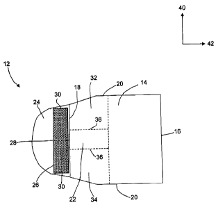
Force focused fastening system 10 shown in FIG. 2a and 2b is described in
terms of a
longitudinal direction 40 and a transverse direction 42. The longitudinal
direction 40 is
perpendicular to the direction of tension placed on the force focused
fastening system 10. The
CA 02633286 2008-06-12
WO 2007/069227 PCT/IB2006/054902
7
transverse direction 42 is perpendicular to the longitudinal direction 40 and
is parallel to the
tension placed on the force focused fastening system 10. 'The force focused
fastening system 10
comprises a force focused fastening member 122 having an extensible region 14
and an end
region 2.4 disposed transversely from the extensible region 14. The extensible
region has a
proximal edge 16, a distal edge 18 transversely opposite the proximal edge 16
and a pair of
connecting edges 2(3 joining the proximal edge 16 to the distal edge 18.
The end region 24 may be extensible but is preferably nonextensible. The end
region 24
extends transversely from the distal edge 18 and includes a fastener element
26. The fastener
element 26 has a center portion 28 and two end portions 30 longitudinally
spaced from- the center
portions 28. The fastener element 26 can comprise any fastener for joining two
surfaces but
preferably includes surface fasteners such as hook and loop (Velcro),
adhesives, cohesives, and
even magnets.
The extensible region 14 of the force focused fastening meniber 12 has a
modulus
wherein the modulus in a least a portion of the extensible region 14 adjacent
the end region 24
varies longitudinally and comprises at least one high modulus region 22. The
high modulus
region 22 is aligned relative to the center portion 28 of the fastener element
26 away from the
two end portions 30. The extensibility of the high modulus region 22 may be at
least 10% lower
than the extensibility of any other area in the extensible region 14. The
extensibility of the high
modulus region 22 may be at least 25% lower or at least 50% lower than the
extensibility of any
other area in the extensible region 14. Alternatively, the extensibility of
the high modulus region
22 may be at least 10tX) lower, at least 25% lower or at least 50%;z- lower
than the extensibility of
at least one other area in the extensible region 14.
Borders 36 of the high modulus region 2.2 extend transversely along the
extensible region
14. The borders 36 are spaced apart from the two end portions 30 of the
fastener element 26
providing a first region 32 and a second region 34 adjacent the end portions
30 of the fastener
element 26. The extensibility of the first region 32 and the second region 3/1
can be greater than
or equal to 90tXv the extensibility of the high modulus region 22.
Alternatively, the extensibility
of the first and second regions 32, 34 can be greater than or equal to 75% or
greater than or equal
to 50% of the extensibility of the high modulus region 22. In addition, the
extensibility of the
first region 32 can be lower than, equal to, or greater than the extensibility
of the second region
34.
CA 02633286 2008-06-12
WO 2007/069227 PCT/IB2006/054902
8
As shown in FIG. 2b, the high modulus region 22 has a longitudinal length,
L/,, and a
transverse width, Wh. The fastener element 26 has a longitudinal length, Lf,
and a transverse
width, ' 4je The longitudinal length, T:h, of the high modulus region 22 can
be less than or equal
to 80% the length, of the fastener element 26. Alternatively, the longitudinal
length, Lh, of
the high modulus region 22 can be less than or equal to 50% L,, or less than
or equal to 25 %'% f j,.
The width, WI, of the high niodulus region 22 relative to the width, Wf, of
the fastener
element 26 also contributes to reduction in curl. The width, Wh, of the high
modulus region 22
can be equal to or greater than 25% Wf. Alternatively, the width, Wh, of the
high modulus
region 22 can be equal to or greater than 100%'% W,, equal to or greater than
200% Wf or else
cover the full width of the extensible region 14. For embodiments (described
below) where the
width, Wh, of the high modulus region 22 covers the full width of the force
focused fastening
member 12 from the proximal edge 16 to distal edge 18, the width, Wh, of the
high modulus
region 22 may extend transversely and longitudinally, the fall width of the
extensible region 14
providing tension bands directed to regions of an article associated with the
force focused
fastening system 10.
As previously explained, in effort to reduce curling of the fastening element
26 during
fastening, fastening forces are focused toward the center portion 28 of the
fastener element '26
and away from the end portions ail of the fastener element 26. As shown in
FIG1. 3, this can be
accomplished by aligning a longitudinal centerline 46 of the fastener element
26 with a
longitudinal centerline 44 of the high modulus region 22. The longitudinal
centerline 44 of the
high modulus region 222 is aligned relative to the longitudinal centerline 46
of the fastener
element '26 such that the length of an offset 48 between the two is minimal.
The length of the
offset 48 between a longitudinal centerline 44 of the high modulus region 22
and the
longitudinal centerline 46 of the fastener element 26 can be less than 75% the
length of the
fastener element, L.f. Alternatively, the length of the offset 48 can be less
than 25% L i or less
than 10%
Lj
In addition, borders 36 of the high modulus region 2.2 are separated from the
end portions
30 of the fastener element 26 by lengths 45. The lengths 45 separating the end
portions 30 from
the borders 36 can be the same or different. The lengths 45 can be greater
than or equal to 25%
1.;. Alternatively, the high modulus region 22 can he spaced apart from the
two end portions 30
of the fastener elenient 2b such that the borders 36 of the high modulus
region 22 are separated
from the end portions 3Ã3 by lengths 45 greater than or equal 30% L.f.
Preferably the borders 36
CA 02633286 2008-06-12
WO 2007/069227 PCT/IB2006/054902
9
of the high modulus region 22 are separated from the end portions 30 by
lengths greater than or
equal to 4.0% L1.
As illustrated in FIG. 4a - 4d, the high modulus region 22 can he configured a
number of
different ways focusing the fastening forces on the center portion 28 of the
fastener element '26
and away from the end portions 30. The embodiments shown in FIG. 4a and 4b
illustrate high
modulus regions 22 of constant longitudinal length, Lh, extending from the
distal edge 18 of the
extensible region 14 to the proximal edge 16 of the extensible region 14. The
high modulus
region 22 in FIG 4a has a linear configuration where as the high modulus
region 22 in FIG. 4b
has a curvilinear configuration.
Alternatively, the high modulus regions 22 for the embodiments shown in FIG.
4c and 4d
extend from the distal edge 18 of the high modulus region 22 to the proximal
edge 16 of the high
modulus region 22. For these embodiments, the longitudinal length, Lh, changes
from the distal
edge 18 to the proximal edge 16. hi FI(F. 4c, the longitudinal length, Lh,
varies, gradually
increasing from the distal edge 18 to the proximal edge 16. In FIG. 4d the
longitudinal length
continuously increases from the distal edge 18 to the proximal edge 16. In
addition to the
variations in the longitudinal length, of the high modulus region, the modulus
of the high
modulus region 22 can also vary transversely from the distal edge 18 to the
proximal edge 16.
The high modulus region 22 can also be configured to direct tensions toward
regions of
an article such as the leg or waist regions of a diaper described in detail
below. As shown in
FIG. 5a to 5c, the extensible region 14 can comprise two high modulus regions,
22a and 22b,
aligned relative to the center portion 28 of the fastener element 26. FIG. 5a
and 5b illustrate
configurations comprising a first high modulus region 2.2.a and a second high
modulus region
22b extending from the distal edge 18 to the proximal edge 16 of the
extensible region 14. Each
high modulus region 22a, 22b has an end converging on the center portion 28 of
the fastener
element '26 proximate the distal edge 18 of the extensible region 14 and an
opposite end
diverging toward a connecting edge 20 of the extensible region 14. FIG. 5c
illustrates
configuration including a third high modulus region 22c disposed between the
first and second
high modulus regions 2.2a, 22b. For embodiments including multiple high
modulus regions, the
modulus of each of the high modulus regions can be the same or different.
The high modulus region 22 can also be configured to focus forces on the
center portion
28 of the fastening element 26 while at. the same time direct tension towards
one of the two
connecting edges 20 near the proximal edge 16 of the extensible region 14. For
instance, as
CA 02633286 2008-06-12
WO 2007/069227 PCT/IB2006/054902
shown in FIG. 6a and 6b, the high modulus region '22 can extend from the
distal edge 18 to the
proximal edge 16 with the longitudinal length, L, of the high modulus region
22 increasing such
that one of the borders 36 of the high modulus region 22 approaches one of the
connecting edges
of the extensible region 14 but not both. For these embodiments, the high
modulus region 22
can be made to direct tensions toward a region of the wearable article that
enhances fit. For
instance, in a diaper embodiment, the high modulus region 22 can be made to
direct tension
toward a leg region or a waist region.
The extensible region 14 of the force focused fastening member 12 may be
constructed
from a number of different materials. For instance, the extensible region 14
may comprise
conventional elastic materials or stretch laminates. The stretch laminates may
comprise a
laminated structure known as live stretch, previously defined, where an
elastic element is
attached to a substrate while the elastic element is under strain; such that
once the strain is
relieved the laminate forms corrugations or gathers and exhibits a shirred
structure having
elastic-like properties.
Alternatively, the stretch laminate may comprise a mechanically activated
stretch
laminate such as a zero strain stretch laminate. Zero strain stretch laminates
comprise a
laminated structure which includes a first substrate, a second substrate and
an elastic element.
The first substrate and the second substrate, which are typically non-elastic
nonwovens, are
attached to the elastic element in a face to face orientation such that the
elastic element is
sandwiched between the first substrate and the second substrate. The laminated
structure is
mechanically activated enabling it to stretch. Mechanical activation refers to
a process wherein
the nonwoven fibers of the non-elastic substrates are broken, and/or
stretched, within the
nonwoven so that the nonwoven is stretched in a direction along its surfaces
and can be easily
expanded in that direction by partial straightening of the fibers in the
nonwoven. Zero-strain
elastomeric laminates are described in U.S. Patent 5,143,679 issued to Weber
et al., U.S. Patent
5,156,793 issued to Buell et al., and U.S. Patent 5,167,897 issued to Weber.
The extensible region 14 of the force focused fastening members 12 can include
elastic
strands or elastic films. Any suitable elastic film known in the art can be
used. Suitable elastic
films may comprise polypropylene, polyethylene, polyolefins, styrene-isoprene-
styrene, styrene-
butadiene-styrene, or combinations thereof. The basis weight of the films can
range from about
10 gsm to about 100 gsm.
CA 02633286 2010-08-17
11
Suitable elastic strands can be made of a resilient elastic thermoplastic
material. The
elastic strands may be made from liquid elastic that is extruded through a die
to achieve the
desired strand elastic diameter and/or shape. The shape of the extruded
elastic strands is not
limited. For example, typical elastic strands have a circular cross sectional
shape, but
sometimes the elastic strands may have different shapes, such as a trilobal
shape, or a flat
(i.e., "ribbon" like) shape. Suitable elastic strand shapes include
rectangles, circles, ellipses,
diamonds, triangles, parallelograms, trapezoids, wedges or other sections of
circles or
ellipses, other polygons, or other irregular enclosed shapes. Furthermore, the
thickness or
diameter of the elastic strands may vary in order to accommodate a particular
application.
Typically, the thickness of elastic strands may be in the range of about 0.02
mm to about I
mm and the basis weight is in the range of about 20 g/m2 to about 300 g/m2.
The elastic strands can be adhesively attached to the substrate, extruded onto
the
substrate, or printed onto the substrate. Suitable apparatuses for applying
elastic strands in a
longitudinal direction are described in U.S. Publication No. 2004/0238105 Al
and in U.S.
Patent No. 7,222,654 entitled "Apparatus for Producing Elastomeric Nonwoven
Laminates"
filed on April 30, 2004. Apparatuses for applying elastic strands in a
transverse direction, an
angle from the longitudinal direction, or in a curvilinear fashion are
described in U.S.
Publication No. US 2005-0178494 Al entitled "Method of Placing Material
Transversely on a
Moving Web" filed on February 13, 2004. Apparatuses for applying elastic
strands in the
longitudinal direction, an angle from the longitudinal direction, or in a
curvilinear fashion are
described in U.S. Patent No. 7,169,228 entitled "Extrusion Applicator Having
Linear Motion
Operability" filed on April 29, 2004, and in U.S. Patent No. 7,097,710
entitled "Extrusion
Applicator Having Rotational Operability" filed on April 29, 2004.
Suitable apparatuses and methods for printing elastic elements in any
orientation are
described in U.S. Publication No. 2004-0181200A1 entitled "Variable Stretch
Composites
and Methods of Making the Composite" filed on March 29, 2004, and in U.S.
Publication No.
2004- 0193133A1 entitled "Variable Stretch Composites and Methods of Making
the
Composite" filed on March 29, 2004. For the printing of elastic strands, the
individual elastic
strands may be configured as lines or strands generally having widths less
than about 2 mm
and typically less than about 1 mm. Linear elastic strands may be configured
as bands
generally having widths between about 2 mm and about 20 mm and aspect ratios
ranging
from about 2:1 to about 100:1.
CA 02633286 2008-06-12
WO 2007/069227 PCT/IB2006/054902
12
Typically, the thickness of an elastic strand may be in the range of about
0.02 mm to about 5 mm
and the basis weight is in the range of about 20 g/m2 to about 300 g/m2.
The first or second substrates forming the extensible region 14 of the force
focused
fastening members 12 may comprise woven materials, nonwoven materials, films,
combinations
of woven and/or nonwoven materials and/or films, or laminated structures
having woven and/or
nonwoven materials and/or films. Suitable nonwoven materials for use in
accordance with the
present invention may comprise fibers made of polypropylene, polyethylene,
polyester, nylon,
cellulose, polyamide, or combinations of such materials. Fibers of one
material or fibers of
different materials or material combinations may be used in the nonwovens.
Suitable processes
for manufacturing nonwoven materials include spunbond, spunbond meltblown
spunbond
(SMS), spunbond meltblown meltblown spunbond (SMMS), carded and the like.
Other suitable
nonwoven materials include high elongation carded (HEC) nonwovens and deep
activation
polypropylene (DAPP) nonwovens. Any process known in the art may be used to
make the
nonwovens. The basis weight of the first nonwoven and/or second nonwoven may,
for example,
be in the range of about 10 gsm to about 40 gsm.
The first substrate, second substrate and the elastic element may be attached
by any
means of attachment known in the art. Suitable attaching means and/or methods
for attaching
include, but are not limited to, adhesives, cohesives, thermal bonding,
pressure bonding,
mechanical bonding, ultrasonic bonding, coextrusion, extrusion and/or any
combination of any
known methods of attaching such materials.
Differences in the moduli between the high modulus region 22 and other areas
of the
extensible region 14 can be affected by including structural differences in
the regions impacting
these properties. For instance, the extensible region 14 of the force focused
fastening member
12 can be mechanically activated by meshing the extensible region 14 between
first and second
activation rolls each of which comprises a plurality of teeth. The teeth of
the first activation roll
intermesh with the teeth of the second activation roll. Difference in modulus
between the high
modulus region 22 and other areas of the extensible region 14 can be attained
by mechanically
activating portions of the force focused fastening member 12 to different
percentages of strain.
The percentage strain experienced depends on the depth of engagement between
the
intermeshing teeth of the first activation roll and the teeth of the second
activation roll.
Activating portions of the extensible region 14 at smaller depths of
engagement (e.g. shorter
teeth) results in different functional characteristics as compared to portions
activated at larger
CA 02633286 2008-06-12
WO 2007/069227 PCT/IB2006/054902
13
depths of engagement. The portions exposed to the smaller depths of engagement
experience
smaller percentages of strain making them less elastically extensible and
thus, exhibit a larger
modulus. For example, a portion of a force focused fastening member 12 which
was strained to
200% may be able to elastically extend up to about three times its original
length. However, a
portion which was strained to 500% may be able to elastically extend up to
about six times its
original length.
In an alternate embodiment, the extensible region 14 of a force focused
fastening
member 12 may comprise a plurality of elastic elements attached to a
substrate. The difference
in modulus can be attained by altering the spacing of the plurality of elastic
elements. For
example, the spacing between each of the elastic elements in the high modulus
region 22 may be
about 2 mm while the spacing between each of the plurality of elastic elements
in other areas of
the extensible region 14 may be about 1 mm. Assuming the plurality of elastic
elements in the
high modulus region 22 have the same physical and chemical properties as
elastic elements in
other areas of the extensible region 14, the modulus can differ relative to
the spacing.
In another embodiment, difference in modulus can be attained by altering the
properties
of a plurality of elastic elements. For instance, a plurality of elastic
elements in the high
modulus region 22 can have different physical or chemical properties than the
physical or
chemical properties of a plurality of elastic elements in other areas of the
extensible region 14.
For instance, a plurality of elastic elements in the high modulus region 22
may have a larger
cross sectional area than a plurality of elastic elements in other areas. For
example, where the
elastic elements comprise elastic strands, the cross sectional area of the
plurality of elastic
elements in the high modulus region 22, can vary from about 0.1 mm2 and less
than or equal to
about 0.4 mm2 whereas the cross sectional area of the plurality of elastic
elements in other areas
of the extensible region 14 can vary from about 0.03 mm2 to about 0.1 mm2.
In another embodiment, the difference in modulus can be attained by providing
additional elastic elements in the high modulus region 22 impacting the
function of that region.
For example, the extensible region 14 of the force focused fastening member 12
may comprise
an elastic element in the extensible region 14. In order to increase the
modulus of the high
modulus region 22, an additional elastic element may be added such that its
modulus is larger
than the modulus of other areas.
The force focused fastening system 10 of the present invention may include
fastener
elements such as tape tabs, interlocking fasteners such as tabs & slots,
buckles, buttons, snaps,
CA 02633286 2008-06-12
WO 2007/069227 PCT/IB2006/054902
14
and/or hermaphroditic fastening components, although any other known fastening
means are
generally acceptable. Preferably, the fastener elements include surface
fasteners such as hock
and loop (Velcro), adhesives, cohesives, and even magnets. Some exemplary
surface fastening
systems are disclosed in U.S. Patent 3,848,594 entitled "Tape Fastening System
for Disposable
Diaper" issued to Buell on November 19, 1974; U.S. Patent B1 4,662,875
entitled "Absorbent
Article" issued to Hirotsu et al. on May 5, 1987; U.S. Patent 4,846,815
entitled "Disposable
Diaper Having An Improved Fastening Device" issued to Scripps on July 11,
1989; U.S. Patent
4,894,060 entitled "Disposable Diaper With Improved Hook Fastener Portion"
issued to
Nestegard on January 16, 1990; U.S. Patent 4,946,527 entitled "Pressure-
Sensitive Adhesive
Fastener And Method of Making Same" issued to Battrell on August 7, 1990; the
herein before
referenced U.S. Pat. No. 5,151,092 issued to Buell on September 9, 1992; and
U.S. Pat. No.
5,221,274 issued to Buell on June 22, 1993. An exemplary interlocking
fastening system is
disclosed in co-pending U.S. Patent No. 6,432,098 entitled "Absorbent Article
Fastening
Device" in the names of Kline et al. issued on August 13, 2002. The fastening
system may also
provide a means for holding the article in a disposal configuration as
disclosed in U.S. Pat. No.
4,963,140 issued to Robertson et al. on October 16, 1990. The fastening system
may also
include primary and secondary fastening systems, as disclosed in U.S. Pat. No.
4,699,622
entitled "Disposable Diaper Having An Improved Side Closure" issued to
Toussant et al. on
October 13, 1987.
The force focused fastening system 10 constructed in accordance with the
present
invention is adaptable to a number of wearable articles. Such wearable
articles include
disposable absorbent articles including diapers, pant style diapers, training
pants, incontinence
briefs, incontinence undergarments, absorbent inserts, diaper holders, liners,
feminine hygiene
garments, thermal pads, bibs and the like. Other articles include body wraps,
surgical garments
and packaging closures. One embodiment of a wearable article incorporating the
force focused
fastening system 10 of the present invention is a unitary disposable absorbent
article, such as the
diaper.
FIG. 7 is a plan view of the diaper 50 including first fastening members 90
and a second
fastening member 92 where the first fastening members 90 comprises a force
focused fastening
member 12 including fastener element 26 and the second fastening member 92
comprises a
landing zone 94. For this embodiment, both the fastener elements 26 and the
landing zone 94
can comprise a hook or loop fastening components. The diaper 50 is shown in a
flat-out state
CA 02633286 2008-06-12
WO 2007/069227 PCT/IB2006/054902
with the garment facing side facing the viewer. The diaper 50 has a first
waist region 86, a
second waist region 88 opposed to the first waist region 86 and a crotch
region 87 located
between the first waist region 86 and the second waist region 88. The
periphery of the diaper 50
is defined by the outer edges of the diaper 50 in which longitudinal edges 70
run generally
parallel to the longitudinal centerline 100 of the diaper 50 and end edges 72
run between the
longitudinal edges 70 generally parallel to the lateral centerline 110 of the
diaper 50.
In FIG. 8, the diaper 50 is shown in a flat-out state with the portion of the
diaper 50
which faces the wearer oriented towards the viewer. As shown in FIG. 8,
portions of the
structure are cut-away to more clearly show the construction of the diaper 50.
The diaper 50
comprises a liquid pervious topsheet 54; a liquid impervious backsheet 56; an
absorbent core 58
which is preferably positioned between at least a portion of the topsheet 54
and the backsheet 56;
extensible leg cuffs 62, and elastic waist features 64. The chassis 52 of the
diaper 50 comprises
the main body of the diaper 50 and includes the topsheet 54 and/or the
backsheet 56 and at least
a portion of the absorbent core 58. While the topsheet 54, the backsheet 56,
the absorbent core
28, force focused fastening members 12 and other aforementioned constituents
may be
assembled in a variety of well known configurations, preferred diaper
configurations are
described generally in U.S. Pat. No. 3,860,003 entitled "Contractible Side
Portions for
Disposable Diaper" issued to Kenneth B. Buell on January 14, 1975; U.S. Pat.
No. 5,151,092
issued to Buell on September 9, 1992; and U.S. Pat. No. 5,221,274 issued to
Buell on June 22,
1993; and U.S. Pat. No. 5,554,145 entitled "Absorbent Article With Multiple
Zone Structural
Elastic-Like Film Web Extensible Waist Feature" issued to Roe et al. on
September 10, 1996;
U.S. Pat. No. 5,569,234 entitled "Disposable Pull-On Pant" issued to Buell et
al. on October 29,
1996; U.S. Pat. No. 5,580,411 entitled "Zero Scrap Method for Manufacturing
Side Panels for
Absorbent Articles" issued to Nease et al. on December 3, 1996; and U.S.
Patent No. 6,004,306
entitled "Absorbent Article With Multi-Directional Extensible Side Panels"
issued to Robles et
al. on December 21, 1999.
The force focused fastening members 12 can have a number of different sizes
and
shapes, but for this embodiment, the force focused fastening members 12
preferably have a
trapezoidal shape. The extensible region 14 of the force focused fastening
members 12 can be
elastic or extensible to provide a more comfortable and contouring fit by
initially conformably
fitting the diaper 50 to the wearer and sustaining this fit throughout the
time of wear. As such,
the force focused fastening members 12 can be made to provide a sustained fit
well past when
CA 02633286 2008-06-12
WO 2007/069227 PCT/IB2006/054902
16
the diaper 50 has been loaded with exudates by allowing the sides of the
diaper 50 to expand and
contract. The force focused fastening members 12 can also be made to provide
more effective
application of the diaper 50 because even if one force focused fastening
member 12 is pulled
farther than the other during application, the diaper 50 will "self-adjust"
during wear.
The force focused fastening members 12 may comprise a separate element affixed
to the
chassis 52, or can be constructed as an extension of other elements of the
diaper such as the
backsheet 56 or the topsheet 54, preferably both the topsheet 54 and the
backsheet 56. In the
embodiment shown in FIG. 7, the force focused fastening members 12 each
comprise a separate
web joined to the chassis 52 in the second waist region 38 and extend
laterally outwardly beyond
the longitudinal edges 70. The force focused fastening members 12 comprise an
extensible
region 14 having a proximal edge 16 and a distal edge 18 and two connecting
edges 20. A first
connecting edge 20 positioned adjacent the end edge 72 of the diaper 50, a
second connecting
edge 20 positioned away from the first end edge 72 towards the lateral
centerline 110. The
proximal edge 16 is attached to the longitudinal edge 70, and the distal edge
18 positioned
laterally outwardly from the longitudinal edge 70. The proximal edge 16 may be
contiguous with
the longitudinal edge 70, preferably the proximal edge 16 is positioned
laterally inwardly of the
longitudinal edge 70. The force focused fastening members 12 includes an end
region 24
extending from the distal edge 18 of the extensible region 14. The end region
24 may be elastic
or nonelastic. Fastener element 26 is attached to the end region 24.
While the diaper 50 shown in FIG. 7 and FIG. 8 has the force focused fastening
members
12 disposed in the second waist region 88, the diaper 50 may be provided with
force focused
fastening members 12 disposed in the first waist region 86 or in both the
first waist region 86
and the second waist region 88. The force focused fastening members 12 may be
constructed in
any suitable configurations. Examples of diapers with side panels having
extensible regions are
disclosed in U.S. Patent 4,857,067, entitled "Disposable Diaper Having Shirred
Ears" issued to
Wood, et al. on August 15, 1989; U.S. Patent 4,381,781 issued to Sciaraffa, et
al. on May 3,
1983; U.S. Patent 4,938,753 issued to Van Gompel, et al. on July 3, 1990; the
herein before
referenced U.S. Pat. No. 5,151,092 issued to Buell on September 9, 1992; U.S.
Pat. No. 5,
221,274 issued to Buell on June 22, 1993; U.S. Patent No. 5,669,897 issued to
LaVon, et al. on
September 23, 1997 entitled "Absorbent Articles Providing Sustained Dynamic
Fit"; and U.S.
Patent No. 6,004,306 entitled "Absorbent Article With Multi-Directional
Extensible Side
Panels" issued to Robles et al. on December 21, 1999.
CA 02633286 2008-06-12
WO 2007/069227 PCT/IB2006/054902
17
The diaper 50 may comprise at least one elastic waist feature 64 that helps to
provide
improved fit and containment. The elastic waist feature 64 is generally
intended to elastically
expand and contract to dynamically fit the wearer's waist. The elastic waist
feature 64 preferably
extends at least longitudinally outwardly from at least one waist edge 76 of
the absorbent core 58
and generally forms at least a portion of the end edge 72 of the diaper 50.
Disposable diapers are
often constructed so as to have two elastic waist features, one positioned in
the first waist region
86 and one positioned in the second waist region 88. Further, while the
elastic waist feature 64
or any of its constituent elements may comprise one or more separate elements
affixed to the
diaper 50, the elastic waist feature 64 may be constructed as an extension of
other elements of
the diaper 50, such as the backsheet 56, the topsheet 54, or both the
backsheet 56 and the
topsheet 54.
The elastic waist feature 64 in the second waist region 88 provides an
extensible member
that provides a more comfortable and contouring fit by initially conformably
fitting the diaper to
the wearer and sustaining this fit throughout the time of wear well past when
the diaper has been
loaded with exudates since the extensible waist feature, particularly in the
back portion of the
diaper allows the diaper to expand and, preferably, to contract. Further, the
elastic waist feature
64 in the second waist region 88 develops and maintains wearing forces
(tensions) that enhance
the tensions developed and maintained by the closure system to maintain the
diaper on the
wearer and enhance the fit of the diaper 50 about the waist of the wearer. The
elastic waist
feature 64 in the second waist region 88 further provides more effective
application of the diaper
50 since even if the caregiver pulls one side of the elastic waist feature
farther than the other
during application (asymmetrically), the diaper will "self-adjust" during
wear.
The elastic waist feature 64 may be attached to the outer, garment facing
surface of the
backsheet 56; the body facing surface of the topsheet 54 or both. In addition
the elastic waist
feature 64 may be attached between the topsheet 54 and the backsheet 56, or
wrapped around the
end edges 72 of the diaper 50 and attached to both the body-facing surface of
the topsheet 54 and
the garment-facing surface of the backsheet 56.
The elastic waist feature 64 may be constructed in a number of different
configurations.
For instance, the elastic waist feature 64 may comprise a laminate structure
consisting of a single
layer of nonwoven with an elastomeric material attached covering a full width
dimension of the
nonwoven or only a portion of the width. The elastomeric material may include
an elastomer
extruded onto the nonwoven or a film that is glued to the nonwoven.
Alternatively, the elastic
CA 02633286 2008-06-12
WO 2007/069227 PCT/IB2006/054902
18
waist feature 64 may comprise a laminate structure comprising two layers of
nonwoven with
elastomeric strands disposed therebetween covering the full width of the
laminate or only a
portion of the width. In addition, the elastic waist feature 64 may be
constructed according to
U.S. Pat. No. 4,515,595 issued to Kievit et al. on May 7, 1985; U.S. Pat. No.
4,710,189 issued to
Lash on December 1, 1987; U.S. Pat. No. 5, 151,092 issued to Buell on
September 9, 1992; and
U.S. Pat. No. 5,221,274 issued to Buell on June 22, 1993. Other suitable waist
configurations
may include waist cap features such as those described in U.S. Pat. No.
5,026,364 issued to
Robertson on June 25, 1991 and U.S. Pat. No. 4,816,025 issued to Foreman on
March 28, 1989.
The diaper 50 can also comprise extensible leg cuffs 62 for providing improved
containment of liquids and other body exudates. Each extensible leg cuff 62
may comprise
several different embodiments for reducing the leakage of body exudates in the
leg regions. (The
leg cuff can be and is sometimes also referred to as leg bands, leg flaps,
barrier cuffs, or elastic
cuffs.) The extensible leg cuffs 62 may be attached to the outer, garment
facing surface of the
backsheet; the body facing surface of the topsheet or both. In addition, the
extensible leg cuffs
62 may be attached between the topsheet and the backsheet, or wrapped around
the longitudinal
edges 70 of the diaper 50 and attached to both the body-facing surface of the
topsheet 54 and the
garment-facing surface of the backsheet 56.
Like the elastic waist feature 64, the extensible leg cuffs 62 may be
constructed in a
number of different configurations. For instance, the extensible leg cuffs 62
may comprise a
laminate structure consisting of a single layer of nonwoven with an
elastomeric material attached
covering a full width dimension of the nonwoven or only a portion of the
width. The
elastomeric material may include an extruded elastic strand laminate
comprising prestrained
extruded elastic strands laminated to a nonwoven or a film that is
subsequently glued to the
garment facing surface of the backsheet along the longitudinal edges 70 of the
diaper 50 and
allowed to relax to form a shirred or corrugated structure. Alternatively, the
extensible leg cuffs
62 may comprise a laminate structure comprising two layers of nonwoven with
prestrained
extruded elastic strands laminated between the two layers of nonwoven covering
the full width
of the laminate or only a portion of the width. The laminate structure can be
subsequently glued
to the garment facing surface of the backsheet along the longitudinal edges 70
of the diaper 50
while in the prestrained condition so that a shirred or corrugated structure
is formed once tension
is removed from the laminate allowing it to relax. In addition, the extensible
leg cuffs 62 may
CA 02633286 2008-06-12
WO 2007/069227 PCT/IB2006/054902
19
comprise a prestrained elastic strand or strands bonded in a prestrained
condition between a
portion of the backsheet or topsheet that is folded over.
In addition, the extensible leg cuffs 62 may be constructed according to one
or more of
the patents described hereunder. U.S. Pat. No. 3,860,003 entitled
"Contractable Side Portions
For a Disposable Diaper", issued to Buell on Jan. 14, 1975, describes a
disposable diaper
providing a contractible leg opening having a leg flap and one or more elastic
members to
provide an elasticized leg cuff (gasketing cuff). U.S. Pat. No. 4,909,803
entitled "Disposable
Absorbent Article Having Elasticized Flaps" issued to Aziz & Blaney on Mar.
20, 1990,
describes a disposable diaper having "stand-up" elasticized flaps (barrier
cuffs) to improve the
containment of the leg regions. U.S. Pat. No. 4,695,278 entitled "Absorbent
Article Having Dual
Cuffs" issued to Lawson on Sep. 22, 1987, describes a disposable diaper having
dual cuffs
including a gasketing cuff and a barrier cuff. U.S. Pat. No. 4,704,115
entitled "Disposable Waste
Containment Garment" issued to Buell on Nov. 3, 1987, discloses a disposable
diaper or
incontinent garment having side-edge- leakage-guard gutters configured to
contain free liquids
within the garment. U.S. Pat. No. 5,032,120 entitled "Disposable Absorbent
Article Having
Improved Leg Cuffs" issued to Freeland & Allen on Jul. 16, 1991, discloses an
absorbent article
having leg cuffs having a relatively low ultimate contact force at relatively
high elongations
accomplished, for example, by low contact force differential material. U. S.
Pat. No. 5, 087,255
entitled "Absorbent Article Having Inflected Barrier Cuffs" issued to Sims on
Feb. 11, 1992,
discloses an absorbent article having inflected barrier cuffs with the distal
edge positioned
outboard of the proximal edge in one waist region and inboard in the other to
provide better fit
about the hips/buttocks.
The extensible regions 14 of the force focused fastening members 12 can be
made to
further enhance fit of the diaper about a wearer by coordinating with the leg
and waist regions of
the diaper. For instance, the elastic waist feature 64 in the second waist
region 88 can be made
to extend into one or both of the force focused fastening members 12 partially
or fully covering
the region above the high modulus region 22 in one or both of the force
focused fastening
members 12. Similarly, the extensible leg cuffs 32 can be made to extend into
one or both of the
force focused fastening members 12 partially or fully covering the region
below the high
modulus region 22 in one or both of the force focused fastening members 12.
Alternatively, the
high modulus region 22 of each of the force focused fastening members 12 can
be oriented to
direct tension into the leg and/or waist regions 62, 64.
CA 02633286 2010-08-17
Other components of the chassis 52 include the backsheet 56, the topsheet 54
and the
core 58. The backsheet 56 is generally that portion of the diaper 50
positioned adjacent garment
facing surface of the absorbent core 58 which prevents the exudates absorbed
and contained
therein from soiling articles which may contact the diaper 50, such as bed
sheets and
undergarments. In preferred embodiments, the backsheet 56 is impervious to
liquids (e.g., urine)
and comprises a thin plastic film such as a thermoplastic film having a
thickness of about 0.012
nun (0.5 mil) to about 0.051 mm (2.0 mils). Suitable backsheet films include
those
manufactured by Tredegar Corporation, based in Richmond, VA, and sold under
the trade name
CPC2 film. Other suitable backsheet materials may include breathable materials
which permit
vapors to escape from the diaper 50 while still preventing exudates from
passing through the
backsheet 56. Exemplary breathable materials may include materials such as
woven webs,
nonwoven webs, composite materials such as film-coated nonwoven webs,
microporous films
I'M
such as manufactured by Mitsui Toatsu Co., of Japan under the designation
ESPOIR NO and by
T.M
Tredegar Corporation of Richmond, VA and sold under the designation EXAIRE.,
and
monolithic films such as manufactured by Clopay Corporation, Cincinnati, OH
under the name
IM
HYTREL blend P18-3097. Some breathable composite materials are described in
greater detail
in PCT Application No. WO 95/16746 published on June 22, 1995 in the name of
E. I. DuPont;
U.S. Patent No. 5,938,648 issued on August 17, 1999 to LaVon et al.; U.S. Pat.
No. 5,865,823
issued on February 2, 1999 in the name of Curro; and U.S. Pat. No. 5,571,096
issued to Dobrin
et al. on November 5, 1996.
The backshect 56, or any portion thereof, may be elastically extensible in one
or more
directions. In one embodiment, the backsheet 56 may comprise a structural
elastic-like film
("SELF") web. A structural elastic-like film web is an extensible material
that exhibits an elastic-
like behavior in the direction of elongation without the use of added elastic
materials and is
described in more detail in U.S. Patent No. 5,518,801 entitled "Web Materials
Exhibiting
Elastic-Like Behavior" issued to Chappell, et al. on May 21, 1996. In
alternate embodiments,
the backsheet 56 may comprise elastomeric films, foams, strands, or
combinations of these or
other suitable materials with nonwovens or synthetic films.
The backsheet 56 may he joined to the topsheet 54, the absorbent core 58 or
any other
element of the diaper 50 by any attachment means known in the art. For
example, the
attachment means may include a uniform continuous layer of adhesive, a
patterned layer of
adhesive, or an array of separate lines, spirals, or spots of adhesive. One
preferred attachment
CA 02633286 2008-06-12
WO 2007/069227 PCT/IB2006/054902
21
means comprises an open pattern network of filaments of adhesive as disclosed
in U.S. Patent
4,573,986 entitled "Disposable Waste-Containment Garment", which issued to
Minetola et al. on
March 4, 1986. Other suitable attachment means include several lines of
adhesive filaments
which are swirled into a spiral pattern, as is illustrated by the apparatus
and methods shown in
U.S. Patent 3,911,173 issued to Sprague, Jr. on October 7, 1975; U.S. Patent
4,785,996 issued to
Ziecker, et al. on November 22, 1978; and U.S. Patent 4,842,666 issued to
Werenicz on June 27,
1989. Adhesives which have been found to be satisfactory are manufactured by
H. B. Fuller
Company of St. Paul, Minnesota and marketed as HL-1620 and HL 1358-XZP.
Alternatively,
the attachment means may comprise heat bonds, pressure bonds, ultrasonic
bonds, dynamic
mechanical bonds, or any other suitable attachment means or combinations of
these attachment
means as are known in the art.
The topsheet 54 is preferably positioned adjacent body surface of the
absorbent core 58
and may be joined thereto and/or to the backsheet 56 by any attachment means
known in the art.
Suitable attachment means are described above with respect to means for
joining the backsheet
56 to other elements of the diaper 50. In one preferred embodiment of the
present invention, the
topsheet 54 and the backsheet 56 are joined directly to each other in some
locations and are
indirectly joined together in other locations by directly joining them to one
or more other
elements of the diaper 50.
The topsheet 54 is preferably compliant, soft-feeling, and non-irritating to
the wearer's
skin. Further, at least a portion of the topsheet 54 is liquid pervious,
permitting liquids to readily
penetrate through its thickness. A suitable topsheet may be manufactured from
a wide range of
materials, such as porous foams, reticulated foams, apertured plastic films,
or woven or
nonwoven materials of natural fibers (e.g., wood or cotton fibers), synthetic
fibers (e.g.,
polyester or polypropylene fibers), or a combination of natural and synthetic
fibers. If the
topsheet 54 includes fibers, the fibers may be spunbond, carded, wet-laid,
meltblown,
hydroentangled, or otherwise processed as is known in the art. One suitable
topsheet 54
comprising a web of staple-length polypropylene fibers is manufactured by
Veratec, Inc., a
Division of International Paper Company, of Walpole, MA under the designation
P-8.
Suitable formed film topsheets are described in U.S. Pat. No. 3,929,135,
entitled
"Absorptive Structures Having Tapered Capillaries" issued to Thompson on
December 30, 1975;
U.S. Pat. No. 4,324,246 entitled "Disposable Absorbent Article Having A Stain
Resistant
Topsheet" issued to Mullane, et al. on April 13, 1982; U.S. Patent 4,342,314
entitled "Resilient
CA 02633286 2010-08-17
22
Plastic Web Exhibiting Fiber-Like Properties" issued to Radel, et al. on
August 3, 1982; U.S.
Pat. No. 4,463,045 entitled "Macroscopically Expanded Three-Dimensional
Plastic Web
Exhibiting Non-Glossy Visible Surface and Cloth-Like Tactile Impression"
issued to Ahr, et al.
on July 31, 1984; and U.S. Pat. No. 5,006,394 "Multilayer Polymeric Film"
issued to Baird on
April 9, 1991. Other suitable topsheets may be made in accordance with U.S.
Pat. Nos.
4,609,518 and 4,629,643 issued to Curro et al. on September 2, 1986 and
December 16, 1986,
respectively. Such formed films are available from The Procter & Gamble
Company of
Cincinnati, Ohio as "DRI-WEAVE" and from Tredegar Corporation, based in
Richmond, VA, as
"CLIFF-T."
Preferably, at least a portion of the topsheet 54 is made of a hydrophobic
material or is
treated to be hydrophobic in order to isolate the wearer's skin from liquids
contained in the
absorbent core 58. If the topsheet 54 is made of a hydrophobic material,
preferably at least a
portion of the upper surface of the topsheet 54 is treated to be hydrophilic
so that liquids will
transfer through the topsheet more rapidly. The topshect 54 can be rendered
hydrophilic by
treating it with a surfactant or by incorporating a surfactant into the
topsheet. Suitable methods
for treating the topsheet 54 with a surfactant include spraying the topsheet
54 material with the
surfactant and/or immersing the material into the surfactant. A more detailed
discussion of such
a treatment and hydrophilicity is contained in U.S. Pat. No. 4,988,344
entitled "Absorbent
Articles with Multiple Layer Absorbent Layers" issued to Reising, et al. on
Jan. 29, 1991 and
U.S. Pat. No. 4,988,345 entitled "Absorbent Articles with Rapid Acquiring
Absorbent Cores"
issued to Reising on Jan. 29, 1991. A more detailed discussion of some
suitable methods for
incorporating a surfactant in the topsheet 54 can be found in U.S. Statutory
Invention
Registration No. H 1670 published on July 1, 1997 in the names of Aziz at al.
Alternatively, the
topsheet 54 may include an apertured web or film which is hydrophobic. This
may be
accomplished by eliminating the hydrophilizing treatment step from the
production process
and/or applying a hydrophobic treatment to the topsheet 54, such as a
polytetraflouroethylene
tM
compound like SCOTCHGUARD or a hydrophobic lotion composition, as described
below. In
such embodiments, it is preferred that the apertures be large enough to allow
the penetration of
aqueous fluids like urine without significant resistance.
The absorbent core 58 may comprise any absorbent material which is generally
compressible, conformable, non-irritating to the wearer's skin, and capable of
absorbing and
retaining liquids such as urine and other certain body exudates. The absorbent
core 58 may he
CA 02633286 2008-06-12
WO 2007/069227 PCT/IB2006/054902
23
manufactured in a wide variety of sizes and shapes (e.g., rectangular,
hourglass, "T"-shaped,
asymmetric, etc.) and may comprise a wide variety of liquid-absorbent
materials commonly used
in disposable diapers and other absorbent articles such as comminuted wood
pulp, which is
generally referred to as airfelt. Examples of other suitable absorbent
materials include creped
cellulose wadding; meltblown polymers, including coform; chemically stiffened,
modified or
cross-linked cellulosic fibers; tissue, including tissue wraps and tissue
laminates; absorbent
foams; absorbent sponges; superabsorbent polymers; absorbent gelling
materials; or any other
known absorbent material or combinations of materials.
The configuration and construction of the absorbent core 58 may also be varied
(e.g., the
absorbent core(s) or other absorbent structure(s) may have varying caliper
zones, hydrophilic
gradient(s), a superabsorbent gradient(s), or lower average density and lower
average basis
weight acquisition zones; or may comprise one or more layers or structures).
Exemplary
absorbent structures for use as the absorbent core 58 are described in U.S.
Patent 4,610,678
entitled "High-Density Absorbent Structures" issued to Weisman et al. on
September 9, 1986;
U.S. Patent 4,673,402 entitled "Absorbent Articles With Dual-Layered Cores"
issued to
Weisman et al. on June 16, 1987; U.S. Patent 4,834,735 entitled "High Density
Absorbent
Members Having Lower Density and Lower Basis Weight Acquisition Zones" issued
to
Alemany et al. on May 30, 1989; U.S. Patent 4,888,231 entitled "Absorbent Core
Having A
Dusting Layer" issued to Angstadt on December 19, 1989; U.S. Pat. No.
5,137,537 entitled
"Absorbent Structure Containing Individualized, Polycarboxylic Acid
Crosslinked Wood Pulp
Cellulose Fibers" issued to Herron et al. on August 11, 1992; U.S. Patent
5,147,345 entitled
"High Efficiency Absorbent Articles For Incontinence Management" issued to
Young et al. on
September 15, 1992; U.S. Pat. No. 5,342,338 entitled "Disposable Absorbent
Article For Low-
Viscosity Fecal Material" issued to Roe on August 30, 1994; U.S. Pat. No.
5,260,345 entitled
"Absorbent Foam Materials For Aqueous Body Fluids and Absorbent Articles
Containing Such
Materials" issued to DesMarais et al. on November 9, 1993; U.S. Pat. No.
5,387,207 entitled
"Thin-Until-Wet Absorbent Foam Materials For Aqueous Body Fluids And Process
For Making
Same" issued to Dyer et al. on February 7, 1995; and U.S. Pat. No. 5,625,222
entitled
"Absorbent Foam Materials For Aqueous Fluids Made From High Internal Phase
Emulsions
Having Very High Water-To-Oil Ratios" issued to DesMarais et al. on July 22,
1997.
Force Focusing Method
CA 02633286 2008-06-12
WO 2007/069227 PCT/IB2006/054902
24
All testing is to occur in conditions controlled to 22 C 2 C, 50% Relative
Humidity
10% Relative Humidity. Samples are conditioned at these conditions at least 24
hours prior to
testing. All distance measures made to the nearest 0.1 mm, using a calibrated
caliper or image
analysis system.
Creation of Sample Strips
1. Procure a representative fastening member and identify longitudinal
direction 40 and
transverse directions 42. Extensibility is to be in at least the transverse
direction 42.
2. As shown in FIG. 9, mark a plurality of grid lines 120 on the fastening
member, each
grid line 120 parallel to (within 2 degrees of) the longitudinal direction
40, with a first
grid line 120 being adjacent the fastening element 26 and the last grid line
being
adjacent to and about 5 mm from the end of the sample proximal edge 16.
a. The grid lines 120 are to spaced 5 mm apart.
b. Each grid line 120 is to be no more than 1 mm wide.
c. The color of the grid lines 120 is to be of sufficient contrast in color to
be readily
distinguishable from the background substrate material color.
d. The grid lines 120 are to be of a material that does not significantly
interfere with
the extension of the extensible region, such as ink from a fine-point marker.
e. The sample is not to be extended during steps 1 and 2
3. Prepare the sample to be cut laterally into a plurality of strips:
a. If the fastening member's extensible region is not a rectangle, cut it into
a
rectangle as shown in FIG. 10a and 10b (grid lines not shown for simplicity).
The uppermost edge is to coincide with either a point U along the innermost
upper edge of the end region or the uppermost location that allows a
continuous
line to be cut. The lowermost edge is to coincide with either a point L along
the
innermost lower edge of the end region or the lowermost location that allows a
continuous line to be cut.
b. Mark locations for cut lines 122 in 5 mm increments, beginning 5 mm from
the
uppermost edge of the sample (FIG. 10a), with each cut line 122 parallel to
the
uppermost edge of the initial rectangle.
c. Mark each strip with an identifying code to identify longitudinal location
within
the fastening member.
d. Cut the sample along the cut lines to create sample strips.
CA 02633286 2010-08-17
e. If the strip adjacent the lowermost edge is < 5 nmi, discard it.
4. Create a grid worksheet, with the same number of columns and rows as have
been
constructed on the sample (see FIG 12a).
Measurement of % Extensions of Sample Strips
1. Mount a digital camera (minimum 4 mega pixel, with optical zoom; a suitable
camera is
tM
the Kodak FasyShare DX6490 available from the Eastern Kodak Co., Rochester,
NY)
perpendicular to the sample's surface (as defined by the longitudinal and
lateral directions
of the sample in the grips) on a tripod 50 cm away from the sample surface,
with the
sample centered in the camera's field of vision and the camera in focus. To
preserve the
image quality, only use the camera's optical zoom, not its digital zoom. The
camera can
not be moved or its magnification altered throughout the experiment.
2. The sample strips are extended in their original transverse direction 42
(Figure 10a) using
a constant rate of extension tensile tester with computer interface (a
suitable instrument is
tM
the M'1'S Alliance using'l'estworks 4.0 Software, as available front MTS
Systems Corp.,
Eden Prairie, MN). The tensile tester is fitted with a 10 N load cell and two
2.54 cm x 2.54
cm rubber faced grips are used for both the stationary and movable pneumatic
jaws.
3. Measure the initial, unextended distance DT from the first grid line to the
last grid line as
shown in 11G. 1 Ia. Set the gage length of the tensile tester to that distance
DT, and reset
the crosshead to zero.
4. Secure the distal end of the sample into the upper grips of the tensile
tester, with the face
of the grip aligned with the first grid line from step 2. At least 5 ntm (in
the lateral
direction) of the end region is placed in the grips. Move the upper grip
closer to the lower
grip to allow the proximal end to be placed in the lower grip without
extending the sample.
5. Secure the proximal end into the lower grip of the tensile tester (Figure l
lb), with the face
of the grip aligned with the last grid line from step 2.
6. Zero the load cell of the tensile tester, and return the cross head to its
original gage length
(i.e. zero position of crosshead).
7. Within 1 second of reaching the defined gage length (distance DT), take a
photograph of
the unextended sample.
8. Move the upper fixture away from the lower fixture at a rate of 127
mm/minute until a
force of 0.5 N/cm is applied to the sample (where Newtons refers to the actual
force
CA 02633286 2008-06-12
WO 2007/069227 PCT/IB2006/054902
26
applied and is normalized to the longitudinal width of the sample in cm).
Within 1 second
of reaching the target load, take a second photograph of the extended sample.
9. Move the upper fixture away from the lower fixture at a rate of 127
mm/minute until a
force of 1.5 N/cm is applied to the sample. Within 1 second of reaching the
target force,
take a third photograph of the extended sample.
10. Move the upper fixture away from the lower fixture at a rate of 127
mm/minute until a
force of 4.0 N/cm is applied to the sample. Within 1 second of reaching the
target load,
take a fourth photograph of the extended sample.
11. Print all four photographs at identical magnification. The scale of the
pictures is to be
such that the size of the sample in the photograph is between 100% and 150% of
actual
size. The first picture can be used to determine the scale by comparing grip
spacing in the
photograph to value DT.
12. From the first picture, measure and record the initial, unextended line-to-
line distances (D1
to Dõ) to the nearest 0.1 mm. The distance is to be measured in the
longitudinal center of
the sample (Figure 11 a) directly parallel to the lateral direction.
13. From the second picture, measure and record the extended line-to-line
distances (E1 to Eõ)
at the first target load to the nearest 0.1 mm. The distance is to be measured
in the
longitudinal center of the sample.
14. From the third picture, measure and record the extended line-to-line
distances (E1 to Eõ) at
the second target load to the nearest 0.1 mm. The distance is to be measured
in the
longitudinal center of the sample.
15. From the fourth picture, measure and record the extended line-to-line
distances (E1 to Eõ)
at the third target load to the nearest 0.1 mm. The distance is to be measured
in the
longitudinal center of the sample.
16. For each applied force, calculate % Extension line-to-line, for each pair
of adjacent lines at
each applied force, with % Extension being:
% Extension = 100 * (E; - D;) / (Di), when i = 1 to n
17. Record the calculated % Extension for each cell on a grid worksheet (such
as shown in
Figure 12a) for each applied force.
18. Repeat steps 4-12 for each strip of the fastening member.
Evaluation of % Extension Grids
CA 02633286 2008-06-12
WO 2007/069227 PCT/IB2006/054902
27
1. Evaluate each of the three grid worksheets (one worksheet per each applied
force) to
determine which one contains the greatest range of % extension.
a. Select a grid worksheet.
b. Compare the % extension values in the upper most horizontal row of the
grid.
The greatest % extension value in this row is Emax upper.
c. Compare the % extension values in the lower most horizontal row of the
grid.
The greatest % extension value in this row is Emax lower.
d. Compare the % extension values in all remaining horizontal rows of the
grid. The
least % extension value in any of these rows is Emin center.
e. Calculate the differences in % extensions using the following:
Difference in % Extension (upper vs. center) = 100 * (Emax-upper - Emin
center) /
Emin center
Difference in % Extension (lower vs. center) = 100 * (Emax lower - Emin
center) /
Emin center
f. Repeat steps 1 a through le for each of the three grid worksheets.
2. Select the grid worksheet with the greatest difference in % extension as
indicated for
either the above equations for further grid analysis.
Mapping of % Extension Regions
1. Identify the row of the grid which is aligned horizontally with the
longitudinal center of
the fastener. Label this row as the middle row of the grid. (note: this row is
not
necessarily equidistant between the top and bottom of the grid.)
2. Identify the upper border for the high % extension regions in each column,
starting with
the far left (distal) column and progressing left to right across the grid.
a. Choose a column.
b. Starting at the middle row and progressing up the column to the top of the
grid,
identify the cells where the % extension is 10% different than the cell
directly
below it. Choose the boarder cell closest to the top of the grid and mark a
boarder
point in the center of the cell.
c. If no boarder cell is found, mark a boarder point at the top vertical edge
of the
grid, centered horizontally in the cell.
d. Repeat steps 2a and 2b for each column of interest.
CA 02633286 2008-06-12
WO 2007/069227 PCT/IB2006/054902
28
e. Mark the upper boarder by connecting each of the boarder points to the
boarder
point in its adjacent column with a line.
3. Identify the lower boarder for the high extension regions in each column,
starting with
the most distal column and ending with the proximal boundary column.
a. Choose a column.
b. Starting at the middle row and progressing down the column to the bottom of
the
grid, identify the cells where the % extension is 10% different than the cell
directly below it. Choose the boarder cell closest to the bottom of the grid
and
mark a boarder point in the center of the cell.
c. If no boarder cell is found, mark a boarder point at the bottom vertical
edge of
the grid, centered horizontally in the cell.
d. Repeat steps 3a and 3b for each column of interest.
e. Mark the lower boarder by connecting each of the boarder points to the
boarder
point in its adjacent column with a line.
4. An example of a completed worksheet is shown in Figure 12b.
Calculations
1. Calculate the relative length of high modulus region adjacent the end
region:
a. Measure the fastener length (LF in Figure 13b) as the maximum linear length
parallel to the longitudinal axis along the inboard edge of the fastening
element.
b. Using the grid worksheet, calculate the length of the low % extension
region (Lh
in Figure 12c) from the most distal column of the worksheet grid. (note: each
cell
represents 5 mm, each half cell is 2.5 mm).
c. Calculate the relative length:
Relative length of high modulus region and fastener = 100 * Lh / LF
2. Calculate the length of offset between longitudinal center line of the high
modulus
region and the longitudinal center line of the fastening element:
a. Measure the fastener length (LF in Figure 13b) as the maximum linear length
parallel to the longitudinal axis along the inboard edge of the fastening
element.
b. Divide the fastening element length (LF in Figure 13b) in half. Measure and
mark
the longitudinal center of fastening element ( distance' LF in Figure 13b).
c. Measure from the upper edge of the grid to the longitudinal center of
fastening
element (distance OF in Figure 13b).
CA 02633286 2008-06-12
WO 2007/069227 PCT/IB2006/054902
29
d. Using the grid worksheet, calculate the offset from the top of the grid to
the
center of the high modulus region (distance Oc in Figure 12c).
e. Calculate the relative location as:
Relative location = 100 * IOF - OCI / LF
3. Calculate the length from end portion to high modulus region:
a. Measure the fastener length (LF in Figure 13b) as the maximum linear length
parallel to the longitudinal axis along the inboard edge of the fastening
element.
b. Divide the fastening element length (LF in Figure 13b) in half. Measure and
mark
the longitudinal center of fastening element (distance' LF in Figure 13b).
c. Measure from the upper edge of the grid to the longitudinal center of
fastening
element (distance OF in Figure 13b).
d. Calculate the distance from the upper edge of the grid to the uppermost
inboard
edge of the fastening element (distance OT in Figure 13b) as OT = OF - 'LF.
e. Calculate the distance from the upper edge of the grid to the lowermost
inboard
edge of the fastening element (distance OB in Figure 13b) as OB = OF +'/2LF.
f. Using the grid worksheet, calculate the offset from the top of the grid to
the
upper boundary of the high modulus region (distance Ou in Figure 12c).
g. Again, using the grid worksheet, calculate the offset from the top of the
grid to
the lower boundary of the high modulus region (distance OL in Figure 12c).
h. Calculate the length from end portion to high modulus region:
Ll = OU - OT and
L2=OB-OL
4. Calculate the relative lateral width of low % extension region:
a. Measure the fastener width (WF in Figure 13a) as the maximum linear length
parallel to the lateral width of the fastener.
b. Determine the lateral width of the low % extension region (WH in Figure
13a):
1. Using the grid worksheet, calculate the longitudinal distance between
the upper and lower boundaries of the low % extension region in the far
left column (Lh in Figure 12c).
2. Move to the next adjacent column to the right.
CA 02633286 2011-08-03
= If this is the proximal boundary column, calculate WH as the
distance between the upper boarder point in this column and the
right edge of the grid.
= Else calculate the distance between the upper and lower
boundary. If this distance is 50% greater than Lt, , calculate WH as
the distance between the upper boarder point in this column and
the right edge of the grid.
= Otherwise repeat this step.
c. Calculate the relative lateral width as:
Relative lateral width = 100 * WH / Wp
All documents cited in the Detailed Description of the Invention are
not to be construed as an
admission that it is prior art with respect to the present invention. To the
extent that any
meaning or definition of the term in a document cited herein, the meaning or
definition assigned to the term in this written document shall govern.
While particular embodiments of the present invention have been illustrated
and
described, it would be obvious to those skilled in the art that various other
changes and
modifications can be made without departing from the scope of the invention.
It is
therefore intended to cover in the appended claims all such changes and
modifications that are
within the scope of this invention.