Note: Descriptions are shown in the official language in which they were submitted.
CA 02633368 2008-06-13
SPECIFICATION
SEMICONDUCTOR MODULE FOR LIGHT RECEPTION OR LIGHT EMISSION
.;
TECHNICAL FIELD
[00011
=;=
The present invention relates to a light receiving or light emitting
semiconductor module in which multiple spherical semiconductor elements having
light receiving or light emitting capability are electrically connected in
series and in
parallel for high output.
BACKGROUND TECHNOLOGY
[0002)
The inventor of the present invention has proposed a spherical semiconductor
=,;
element having light receiving or light emitting capability that has positive
and =
negative electrodes at opposite positions about the center thereof, and a
solar battery
module wherein multiple sets of multiple semiconductor elements are serially
connected in each set and the multiple semiconductor elements are embedded in
a
=
z
synthetic resin material as set forth in the publication of W098/15983. In the
solar
battery module, the semiconductor elements have a spherical form and a
spherical
pn-junction in the surface. Positive and negative electrodes are provided in
the
centers of the surfaces of the p-type and ntype regions forming the pa-
junction.
1
;
*';
CA 02633368 2008-06-13
;
[0003]
The inventor of the present invention has proposed a solar battery module
wherein the above spherical semiconductor elements are arranged in multiple
rows
and columns, the semiconductor elements in each row are connected in parallel
by
conductive members and solder or conductive adhesive, the semiconductor
elements
in each column are connected in series by lead members and solder, and they
are
embedded in a synthetic resin material as set forth in the publication of
W002/35612,
W002/35613, and W003/017382.
[0004]
The inventor of the present invention has further proposed a semiconductor
module having light receiving or light emitting capability wherein multiple
semiconductor elements are embedded in a synthetic resin material as set forth
in
the publication of W003/036731.
[0005]
Recently, solar batteries are increasingly in use as a renewable clean energy
source relative to environmental issues such as air pollution and global
warming and
exhaustion of fossil fuels, Light emitting diodes are also increasingly in use
as
illumination source from the viewpoint of energy and resource saving. There is
also
an increasing need of saving resources for materials and reducing production
energy
consumption.
[0006]
Patent Document 1: W098/15983;
2
CA 02633368 2008-06-13
Patent Document 2; W002/85612;
Patent Document 3: W002/85613;
Patent Document 4: W008/017382; and
Patent Document 5: W003/086731.
DISCLOSURE OF THE INVENTION
PROBLEMS TO BE SOLVED BY THE INVENTION
[00071
In prior art solar battery module or light emitting diode displays, a number
of
,==
granular semiconductor elements are connected to conductive members by solder
or
conductive adhesive and are embedded in a synthetic resin cover casing (outer
enclosure) to form a module. Therefore, a number of semiconductor elements
cannot be separated from the cover casing for recovering them upon disposal of
the
solar battery module. For this reason, it is difficult to recover
semiconductor
elements from solar battery modules or light emitting diode displays and reuse
them.
A resolution taking into account resources and natural environments is
required.
[00081
When a large number of semiconductor elements as described above come to
be in practical use in the near future, their replacement and disposal is
accordingly
increased as a result of deterioration and expiration of life-span. Loads on
resources
and natural environments are likely increased. Particular restriction has been
imposed on the use of their lead-containing solder materials.
3
CA 02633368 2013-04-02
The purpose of the present invention is to provide a light receiving or
= ,
emitting semiconductor module that is applicable to solar battery modules and
=
light emitting diode displays in which multiple granular light receiving or
emitting semiconductor elements are installed and facilitates reuse,
6 reproduction, and repair of multiple semiconductor elements.
PROBLEM RESOLUTION MEANS
[0009]
According to one aspect of the present invention there is provided a light
=receiving or light emitting semiconductor module comprising multiple
spherical
.semiconductor elements having light receiving or light emitting function,
comprising:
positive and negative electrodes provided to each of said multiple
semiconductor elements at
,
'
opposite positions about the center thereof; a holding means for holding said
multiple ; ,
semiconductor elements in a manner that they are arranged in multiple columns
and multiple
rows with their conducting direction aligned in a column direction and
multiple
semiconductor elements are separable individually or in multiple groups; a
conductive
, connection mechanism connecting in series the semiconductor elements in each
column
among multiple columns of semiconductor elements and connecting in parallel
the
semiconductor elements in each row among multiple rows of semiconductor
elements;
conductive elastic members applying a mechanical pressing force in a column
direction to
maintain the serial connection of multiple columns of semiconductor elements
by said
conductive connection mechanism; said holding means has a tabular storage
easing forming a
, flat storage zone for storing multiple semiconductor elements and
comprising multiple
separable members, the storage casing has a pair of casing plates parting
either side of said
storage zone from the outside, and at least one of the casing plates is made
of light
4
CA 02633368 2013-04-02
=
transmissible glass or synthetic resin; said holding means has multiple
conductive wires
arranged in parallel in said storage casing, multiple semiconductor elements
in each row are
held with their positive and negative electrodes clamped by a pair of
conductive wires; said
multiple semiconductor elements are arranged in a matrix of multiple rows and
multiple
columns, multiple semiconductor elements in each row abut against each other
and multiple
semiconductor elements in each column abut against each other with a
conductive wire in
between, and said conductive connection mechanism comprises multiple
conductive wires;
said storage casing has a pair of first outer frames and a pair of second
outer frames provided
around a periphery of said storage zone in a rectangular form between said
pair of casing
plates, said pair of first outer frames is provided on either side of said
storage zone in parallel
to a column direction, and a pair of ends of each of said multiple conductive
wires are fixed
to the pair of first outer frames; and the pair of second outer frames is
provided between a
pair of ends of the pair of first outer frames in parallel to a row direction,
and relay
µ; =
conductors abutting against the conductive wires facing the second outer
frames and
. corrugated springs abutting against the relay conductors and comprising
conductive band
plates are provided between the second outer frames and the conductive wires
facing them.
According to a second aspect of the invention there is provided a light
receiving or light
emitting semiconductor module comprising multiple spherical semiconductor
elements
having a light receiving or light emitting function, comprising: positive and
negative
=
=
electrodes provided to each of said multiple semiconductor elements at
opposite positions
about the center thereof; a holding means for holding said multiple
semiconductor elements
in a manner that they are arranged in multiple columns and multiple rows with
their
conducting direction aligned in a column direction and multiple semiconductor
elements are
separable individually or in multiple groups; a conductive connection
mechanism connecting
in series the semiconductor elements in each column
5
CA 02633368 2013-04-02
among multiple columns of semiconductor elements and connecting in parallel
the
semiconductor elements in each row among multiple rows of semiconductor
elements; =
conductive elastic members applying a mechanical pressing force in a column
direction to
maintain the serial connection of multiple columns of semiconductor elements
by said
conductive connection mechanism; said holding means has a tabular storage
casing forming a
flat storage zone for storing multiple semiconductor elements and comprising
multiple
separable members, the storage casing has a pair of casing plates parting
either side of said
storage zone from the outside, and at least one of the casing plates is made
of light
transmissible glass or synthetic resin; multiple semiconductor elements
divided into multiple
groups; multiple semiconductor elements in each group are arranged in a matrix
of multiple
rows and multiple columns and adjacent semiconductor elements among multiple
semiconductor elements in each row abut against each other or are slightly
spaced from each
other; said conductive connection mechanism has multiple conductive wires
provided
between rows of multiple rows of semiconductor elements and a pair of
connection
conductors provided outside a pair of end rows in a column direction in
parallel to a row
direction; multiple semiconductor elements, multiple conductive wires, a pair
of connection
conductors in each group are partly embedded in a light transmissible
synthetic resin to
constitute a tabular segment module; said multiple segment modules are
serially arranged in
the storage zone of said storage casing and connection conductors of adjacent
segment
modules are electrically connected; said storage casing comprises a pair of
casing plates
superimposed face-to-face, said casing plates each have sidewalls closing the
storage zone at
a pair of ends in the row direction and terminal mounting grooves extending
from the storage
zone to either end of the casing plate in the column direction, and terminal
plates protruding
outside are mounted in a pair of facing terminal mounting grooves of the
storage casing,
respectively, and fixed to the storage casing; and corrugated springs as said
conductive elastic
5A
CA 02633368 2013-04-02
members are mounted between said terminal plates and the connection conductors
of the
segment modules that face the terminal plates, the elastic biasing force of
the pair of
corrugated springs maintains the serial electrical connection of multiple
segment modules,
According to a third aspect of the present invention there is provided a light
receiving or light emitting semiconductor module comprising multiple spherical
= semiconductor elements having light receiving or light emitting function
comprising: positive
and negative electrodes provided to each of said multiple semiconductor
elements at opposite
positions about the center thereof; a holding means for holding said multiple
semiconductor
elements in a manner that they are arranged in multiple columns and multiple
rows with their
conducting direction aligned in a column direction and multiple semiconductor
elements are
separable individually or in multiple stoups; a conductive connection
mechanism connecting
in series the semiconductor elements in each column or in two adjacent columns
among
=
multiple columns of semiconductor elements and connecting in parallel the
semiconductor =,
elements in each row among multiple rows of semiconductor elements; conductive
elastic ,
members applying a mechanical pressing force in a column direction to maintain
the serial
connection of multiple columns of semiconductor elements by said conductive
connection
mechanism; said holding means has a tabular storage casing forming a flat
storage zone for =
storing multiple semiconductor elements and comprising multiple separable
members, the
= storage casing has a pair of casing plates parting either side of said
storage zone from the
outside, and at least one of the casing plates is made of light transraissible
glass or synthetic
resin; and said holding means has multiple corrugated retention springs
arranged nearly in
parallel in said storage casing and comprising conductive band plates,
multiple
semiconductors in each row are held with their positive and negative
electrodes clamped by a
pair of corru.gated retention springs, and said conductive connection
mechanism comprises
said multiple corrugated retention springs.
6B
=
CA 02633368 2013-04-02
According to a fourth aspect of the present invention there is provided a
light receiving
or light emitting semiconductor module comprising multiple spherical
semiconductor
elements having light receiving or light emitting function comprising:
positive and negative
electrodes provided to each of said multiple semiconductor elements at
opposite positions
about the center thereof; a holding means for holding said multiple
semiconductor elements
in a manner that they are arranged in multiple columns and multiple rows with
their
conducting direction aligned in a column direction and multiple semiconductor
elements are
separable individually or in multiple groups; a conductive connection
mechanism connecting
in series the semiconductor elements in each column among multiple columns of
"i
semiconductor elements and connecting in parallel the semiconductor elements
in each row
=
among multiple rows of semiconductor elements; conductive elastic members
applying a
mechanical pressing force in a column direction to maintain the serial
connection of multiple
columns of semiconductor elements by said conductive connection mechanism;
said holding
1r
means has a tabular storage casing forming a flat storage zone for storing
multiple
16 semiconductor elements and comprising multiple separable members, the
storage casing has a
pair of casing plates parting either side of said storage zone from the
outside, and at least one
of the casing plates is made of light transmissible glass or synthetic resin;
multiple
semiconductor elements divided into multiple groups; multiple semiconductor
elements in
each group are arranged in a matrix of multiple rows and multiple columns and
adjacent
semiconductor elements among multiple semiconductor elements in each row abut
against
each other or are slightly spaced from each other; said conductive connection
mechanism has
multiple conductive wires provided between rows of multiple rows of
semiconductor
elements and a pair of connection conductors provided outside a pair of end
rows in a column
direction in parallel to a row direction; and multiple semiconductor elements,
multiple
c.onductive wires, a pair of connection conductors in each group are partly
embedded in a
=
5C ti
CA 02633368 2013-04-02
light transmissible synthetic resin to constitute a tabular segment module;
said multiple
segment modules are serially arranged in the storage zone of said storage
casing and
connection conductors of adjacent segment modules are electrically connected;
said storage
casing comprises a pair of easing plates superimposed face-to-face, said
casing plates each
5' have sidewalls closing the storage zone at a pair of ends in the row
direction and terminal
mounting grooves extending from the storage zone to either end of the casing
plate in the
column direction, and terminal plates protruding outside are mounted in a pair
of facing
terminal mounting grooves of the storage casing, respectively, and fixed to
the storage casing;
>
and said terminal plates are fixed in the manner that their positions are
adjustable in relation
to said storage casing.
100101
1
In this light receiving or light emitting semiconductor module, the
conductive connection mechanism connects in series the semiconductor elements
in each column or the semiconductor elements in two adjacent columns and
=
connects in parallel the semiconductor elements in each row. When some
semiconductor elements or some connection between semiconductor elements
' fails, the current flows through an alternative path bypassing the failed
semiconductor element or disconnected point, effectively operating all normal
semiconductor elements.
If the semiconductor module is a solar battery module, when some
semiconductor elements are disabled because they are shaded, the current flows
through an alternative path as in the above case.
If the semiconductor module is a light emitting diode display, the current
flows through an alternative path as in the above case and all normal
25, semiconductor elements operate effectively.
5D
1,!
CA 02633368 2013-04-02
[001.1]
The conductive connection mechanism has conductive elastic members
applying a mechanical pressing force in the column direction to maintain the
serial connection of multiple columns of semiconductor elements, eliminating
the
connection by solder or conductive adhesive between a semiconductor element
and a conductive member and between conductive members. ___________________
15
5E
CA 02633368 2008-06-13
For disposal or repair of the semiconductor module, the holding means is
disassembled to separate multiple semiconductor elements individually or in
multiple groups. Multiple semiconductor elements can be retrieved individually
or
in groups. Other preferable structures of the present invention will easily be
understood from embodiments of the present invention described later.
ADVANTAGES OF THE INVENTION
=
[0013]
;
The light receiving or light emitting semiconductor module of the present
invention has a holding means for holding multiple semiconductor elements
individually or in multiple groups and conductive elastic members applying a
mechanical pressing force in the column direction to maintain the serial
connection
of multiple columns of semiconductor elements by the conductive connection
mechanism. For disposal or repair of the semiconductor module, multiple
semiconductor elements can be removed individually or in groups, facilitating
reuse,
reproduction, or repair of semiconductor elements, eliminating the need for
prior art
solder or conductive adhesive connection.
BRIEF EXPLANATION OF THE DRAWINGS
[0014]
Fig.1 is a cross-sectional view of a solidified silicon crystal relating to an
embodiment of the present invention.
6
CA 02633368 2008-06-13
Fig.2 is a cross-sectional view of a silicon crystal from which the projection
is
cut away.
Fig.3 is a cross-sectional view of a silicon crystal on which a silicon oxide
film
is formed.
Fig.4 is a cross-sectional view of a silicon crystal from which the silicon
oxide
film is partly removed.
Fig.5 is a cross-sectional view of a silicon crystal on which an n-type
diffused
layer and a pn-junction are formed.
Fig.6 is a cross.sectional view of a silicon crystal on which a silicon oxide
coating is formed.
Fig.7 is a cross-sectional view of a solar battery cell.
Fig.8 is an exploded perspective view of the solar battery module of
Embodiment 1.
Fig.9 is a plane view of the solar battery module of Fig.8.
7
Fig.10 is a horizontal cross-sectional plane view of the solar battery module
of
Fig.8.
Fig.11 is a vertical cross-sectional view of the solar battery module of
Fig.8.
Fig.12 is an exploded perspective view of the solar battery module of
Embodiment 2.
Fig.13 is an enlarged cross-sectional view of the core part of the solar
battery
module of Fig.12.
Fig.14 is an enlarged cross-sectional view of the core part of the solar
battery
7
:
CA 02633368 2008-06-13
module of Fig.12.
Fig.15 is a cross-sectional view at the line XV-XV in Fig.13.
Fig.16 is a cross-sectional view at the line XVI-XVI in Fig.13.
Fig.17 is an equivalent circuit to the solar battery module.
Fig.18 is an exploded perspective view of the solar battery module of
Embodiment 3.
Fig.19 is a cross-sectional view of the solar battery module of Fig.18.
Fig.20 is a cross-sectional view at the line XX-XX in Fig.19.
Fig.21 is a cross-sectional view at the line XXI-XXI in Fig 19,
Fig.22 is a plane view of a segment module of the solar battery module of
Fig.18.
Fig.23 is a cross-sectional view at the line XXLIFXXIII in Fig.22.
Fig.24 is a side view of the segment module seen in the arrowed direction
XXIV in Fig.22.
r.
Fig.25 is a cross-sectional view at the line XXV-XXV in Fig.22.
Fig.26 is a side view of the segment module seen in the arrowed direction
XXVI in Fig.22.
Fig.27 is an equivalent circuit to the solar battery module.
LEGEND
.õ,
[0015]
6 positive electrode
sõ
8
CA 02633368 2008-06-13
6 negative electrode
solar battery cell
11 holding mechanism
12 conductive connection mechanism
5 13 corrugated retention spring
14 storage casing
storage zone
16 outer frame
17 casing plate
10 18, 19 first, second outer frame
23 elastic film
BO, 40 solar battery module
41 holding mechanism
42 conductive connection mechanism
15 42a conductive wire
43 conductive elastic member
43a corrugated spring
44 storage zone
45 storage casing
=,
46 outer frame
47 casing plate
47a silicone rubber coating (elastic film)
9
CA 02633368 2008-06-13
48, 49 first, second outer frame
51 terminal plate
60 solar battery module
61 segment module
62 storage casing
63 casing member
65 storage zone
66 conductive wire
70 corrugated spring
76 external terminal
BEST MODE FOR IMPLEMENTING THE INVENTION
[0016]
The present invention relates to a light receiving or light emitting
semiconductor module comprising multiple spherical semiconductor elements
having
light receiving or light emitting function wherein multiple semiconductor
elements
are separable individually or in multiple groups for disposal or repair of the
semiconductor module.
EMBODIMENT 1
[0017]
First, the solar battery module (light receiving semiconductor module) of
Embodiment 1 will be described. The structure and production method of a
CA 02633368 2008-06-13
==
spherical silicon solar battery cell (semiconductor element) will be described
with
reference to Figs. 1 to 7. The structure and production method of this
spherical
silicon solar battery cell is disclosed in the publication of W003/017882 by
the
inventor of the present invention and is therefore briefly explained here.
[013181
Fig.1 is a cross-sectional view of a p-type spherical silicon crystal 1
(monocrystal or polycrystal) having a diameter of 1.0 to 2.0 mm. The granular
silicon crystal 1 is produced by melting a silicon row material in a crucible
at the top
of a drop tube, discharging silicon droplets from the nozzle orifice of the
crucible and
allowing them to free-fall in the drop tube approximately 14 m. The droplets
shaped
into a sphere due to surface tension during the fall are cooled and solidified
into
spherical crystal and recovered at the bottom of the drop tube. The silicon
crystal 1
of this embodiment is monocrystalline silicon. 'Those solidified at the end of
solidifying process may have a projection as shown in Fig,1. The projection is
16 removed and polished to a sphere.
[0019]
As shown in Fig.2, the surface of the spherical silicon crystal 1 is polished
and
partly flattened to form a reference surface lb, thereby obtaining a silicon
crystal la.
The silicon crystal la has a diameter of approximately 1.8 mm. As shown in
Fig.3, a
silicon oxide film 2 is formed on the entire surface of the silicon crystal la
by a known
thermal oxidation technique. As shown in Fig.4, the silicon oxide film 2 is
removed
except for a silicon oxide film 2a on the reference surface lb and its
vicinity. The
11
=
CA 02633368 2008-06-13
silicon oxide film 2a is used as a mask in the subsequent impurity diffusion.
It is a
known technique to leave such a silicon oxide film in part as above using a
mask.
[00201
As shown in Figs. 4 and 5, an n-type impurity is thermally diffused through
6 the exposed p-type surface lc into the surface by a known thermal diffusion
technique using the silicon oxide film 2a as a mask to form an n-type layer 3,
forming
a nearly spherical pn-junction 3a. The nearly spherical pn-junction 3a is
formed
except for the reference surface lb and its vicinity The silicon oxide film
incidentally generated during the thermal diffusion of n-type impurity is once
=
removed by known chemical etching. Then, the silicon crystal la is again
heated in
an oxygen-containing atmosphere to form on the entire surface a silicon oxide
film 4
to a predetermined thickness as shown in Fig.6. The silicon oxide film 4
serves as
an antireflection coating.
[0021]
16 Subsequently, a silver-based paste is printed in dots on the flat
reference
surface lb (p-type) and on the top (n-type) of the silicon crystal at the
position
opposite to the reference surface lb about the center of the silicon crystal
la and
processed at a high temperature for a short time. Consequently, as shown in
Fig.7,
the paste penetrates the silicon oxide film 4 and makes ohmic contact with the
p-type
silicon reference surface lb and the surface of the n-type layer 3 to form a
positive
electrode 5 and a negative electrode 6, respectively.
[0022]
12
CA 02633368 2008-06-13
The granular and spherical solar battery cell 10 as prepared above has a
spherical pn-junction 3a at a uniform depth below the surface of the silicon
crystal la
and therefore converts photoelectrically incident light from all direction at
a nearly
equal light receiving sensitivity. A spherical light emitting diode having
such a
spherical pn-junction emits uniform light from the spherical surface in all
direction
using the electric energy input from the positive electrode 5.
[0023]
A solar battery module 30 having of a number of the above described spherical
solar battery cells 10 connected in series and in parallel will be described
hereafter
with reference to Figs. 8 to 11. The solar battery module 30 is a double glass
solar
battery module. The solar battery module 80 has a rectangular light receiving
surface of for example approximately 50 mm to 75 mm on a side. This dimension
of
the light receiving surface is given by way of example. A larger solar battery
module can also be constituted.
[0024]
The solar battery module 30 comprises a holding mechanism 11 (holding
means) holding multiple solar battery cells 10 in the manner that they are
arranged
tw,o-dimensionally in multiple columns and multiple rows with their conducting
direction aligned in the column direction and multiple solar battery cells 10
are
individually separable, a conductive connection mechanism 12 connecting in
series
the solar battery cells 10 in two adjacent columns among multiple columns of
solar
battery cells and connecting in parallel the solar battery cells in each row
among
13
CA 02633368 2008-06-13
1
multiple rows of solar battery cells 10, and multiple conductive corrugated
retention
springs 13 serving as conductive elastic members applying a mechanical
pressing
force in the column and row direction to maintain the serial connection of
multiple
solar battery cells 10 by the conductive connection mechanism 12.
[0025] =
The holding mechanism 11 comprises a tabular storage casing 14 and multiple
conductive corrugated retention springs 19. The conductive connection
mechanism
12 comprises multiple corrugated retention springs 13. A fiat rectangular
storage
zone 15 is formed in the storage casing 14 to store multiple solar battery
cells 10.
The storage casing 14 has a rectangular outer frame 16 enclosing the storage
zone 15
and transparent glass casing plates 17 closing the top and bottom sides of the
storage
zone 15 and outer frame 16.
[0026]
The outer frame 16 consists of a pair of first parallel outer frames 18
serving
=
as collective electrodes and a pair of second parallel outer frames 19. The
second
outer frames 19 are provided between the ends of the pair of first outer
frames 18.
The first outer frames 18 have a thickness of approximately 2 mm, each
consisting of
a glass cloth-based epoxy resin insulating member having on the surface a
copper foil
layer (a thickness of approximately 0.1 mm) formed and then silver-plated. The
second outer frames 19 consist of the same insulating members as above. The
second outer frames 19 have on the side to the storage zone 15 multiple slots
20 with
pores to connect and retain the ends of the corrugated springs 13. The first
outer
14
,
,
CA 02633368 2008-06-13
frames 18 have multiple bolt holes 21, on the inner surfaces of which the same
copper
foil and silver plating as above are provided. The second outer frames 19 also
have
one or multiple bolt holes 22.
10027]
In the storage zone 15, multiple corrugated retention springs 13 are provided
nearly in parallel in the manner that the troughs and crests of adjacent
corrugated
retention springs 13 face closely. The ends and spiral parts 18a at the tip of
the
corrugated retention springs 13 are fitted in the slots 20 of the second outer
frames
19 to couple the corrugated retention springs 13 to the second outer frames
19. The
corrugated retention springs 13 are formed by regularly corrugating a phosphor
bronze strip having a thickness of approximately 0.4 ram and a width of
approximately 1.9 ram and silver-plating its surface.
[00281
In the storage zone 15, multiple solar battery cells 10 (a set of solar
battery
cells) are arranged in multiple columns and multiple rows with their
conducting
direction aligned in the column direction. Multiple solar battery cells 10 in
two
adjacent columns are zigzagged. The solar battery cells 10 are clamped and
held
where the troughs and crests of adjacent corrugated retention springs 13 face
closely.
Abutting against a common corrugated retention spring is, the positive
electrodes 5
of the solar battery cells 10 in each row are electrically connected in
parallel.
Abutting against a common corrugated retention spring 13, the negative
electrodes 6 of the solar battery cells 10 in each row are electrically
connected in
CA 02633368 2008-06-13
parallel. A pair of corrugated retention springs 13 at the ends in the column
direction abuts against the inner surfaces of the first outer frames 18,
placing them
at regulated positions and electrically connecting them to the first outer
frames 18.
[0029)
A number of spherical solar battery cells 10 are held by a mechanical pressing
force from multiple conductive corrugated retention springs 13 and
electrically =
connected in the storage zone 15, Among multiple columns of solar battery
cells 10,
the solar battery cells 10 in two adjacent columns are connected in series by
multiple
corrugated retention springs 13 and the solar battery cells 10 in each row are
connected in parallel by the pair of corrugated retention springs 13 on either
side of
the row. The conductive connection mechanism 12 comprises multiple corrugated
retention springs 13. The serial connection of multiple columns of solar
battery
cells 10 is maintained by a mechanical pressing force in the column direction
that is
generated by multiple corrugated retention springs 13.
[0030)
.;
Then, the transparent casing plates 17 are attached and sealed to the outer
frame 16 and storage zone 15 on either side. The casing plates 17 have for
example
a thickness of approximately 3 mm. The casing plates 17 also have an elastic
film
28 consisting of a transparent silicone rubber thin film having a thickness of
approximately 0.2 ram on one surface (the inner surface). The pair of casing
plates
17 is placed on either side in a sandwich structure in which the elastic films
23 make
contact with a set of the solar battery cells and the outer frame 16.
16
CA 02633368 2008-06-13
[0031]
The bolt holes 24 and 25 of the casing plates 17 and the bolt holes 21 and 22
of
the outer frame 16 are then aligned. The casing plates 17 and outer frame 16
are
fastened by steel bolts 26 and nuts 26c with with washers 26a made of
synthetic
resin, for example fiuororesin and steel disc springs 26b. A lead terminal 27
can be
provided to the bolt 26 where necessary. The lead terminal 27 is electrically
connected to the copper foil and silver plating layer on the inner surface of
the bolt
hole 21 via the bolt 26.
[00321
Here, the end corrugated retention springs 13 adjacent to the first outer
frames 18 are in mechanical contact with and maintain electrical connection to
the
inner surfaces of the first outer frames 18 as a result of a pressing force
from the
corrugated retention springs 13.
However, the casing plates 17, outer frame 16, solar battery cells 10, and
multiple corrugated retention springs 13 are not necessarily fastened and
integrated
by the bolts 26 and nuts 26c. Any coupling structure can be used as long as
they are
individually separable.
[0033]
The storage zone 15 can be vacuumed in a vacuum container before fastened
and sealed by the bolts 26 if necessary. In such a case, the vacuumed storage
zone
= 15 is fastened by the bolts 26 and nuts 26c or the storage zone 15 is
fastened with an
inert gas such as nitrogen gas introduced for producing a highly heat
insulated
17
CA 02633368 2008-06-13
double glass solar battery module 30. To this end, it is desirable to provide
a seal
between the first and second outer frames 18 and 19 with a silicone rubber
thin film,
creating a sealed storage zone 15.
[0034
Having multiple solar battery cells 10 retained between two casing plates 17
by the outer frame 16 and multiple corrugated retention springs 18 to allow
for a
proper natural lighting space and room, the double glass solar battery module
30 has
applications as a highly heat and sound insulated natural lighting window also
having an electric power generation function.
[00351
The corrugated retention springs 13 and solar battery cells 10 also serve as a
spacer to keep a uniform distance between the two casing plates 17 and
increase
mechanical strength. For Unproved heat insulation as a window, the casing
plates
17 can have a low-E double glass structure having an infrared reflection
coating such
as silver and tin oxide on the surface.
[00361
The double glass solar battery module 30 can be used by itself or in
combination with another solar battery module 30 having the same structure so
that
it is extended in size and they are electrically connected for larger output.
In such a
case, for example, a connection lead terminal 27 can be attached to the bolt
26
inserted in the first outer frame 18 for module wire connection to the other
solar
battery module 80.
18
CA 02633368 2008-06-13
[0037]
In this double glass solar battery module SO, the spherical solar battery
cells
absorb incident light transmitted through the transparent casing plate 17 and
generate electric power according to the light energy intensity. In this
regard, the
5 solar battery cells 10 absorb not only direct light but also finally light
reflected
multiple times by the corrugated retention springs 13, casing plates 17, and
solar
battery cells 10 within the storage zone 15 and convert it to electric power.
The
natural lighting efficiency or exterior design as a window can be altered by
modifying
the positioning pattern of multiple solar battery modules 30 and the shape of
the
10 corrugated retention springs 13.
[0038]
1
In this double glass solar battery module 30, multiple solar battery cells 10
connected in parallel by a pair of corrugated retention springs 13 are
connected in
series to form a mesh-structure electric circuit. Then, if some solar battery
cells 10
fail and are open or if some solar battery cells 10 are electrically
disconnected or if
some solar battery cells 10 are disabled because they are in shade, the
current flows
through an alternative path bypassing the disabled solar battery cells 10 and
the
other normal solar battery cells 10 do not entirely or partly fail to generate
electric
power.
[00391
The above described solar battery module 30 has the following functions and
advantages.
19
CA 02633368 2008-06-13
(1) The spherical solar battery cells 10 have mechanical strength; therefore,
they can have excellent electric connection to conductors by means of a
pressing force
from the corrugated retention springs 13. Then, the prior art solder or
conductive
adhesive connection is eliminated. The bolts 26 and nuts 26c are simply
disengaged
to easily disassemble the solar battery module 30 and retrieve multiple solar
battery
cells 10 and other parts individually. Therefore, the recovery cost of the
solar
battery cells 10 is significantly lowered compared with the prior art solid
connection
by solder or conductive adhesive.
[00401
(2) The outer frame 16, multiple corrugated retention springs 18, and two
casing plates 17 are mechanically assembled via the bolts 26 and nuts 26c. The
solar battery module 30 can easily be assembled/disassembled, significantly
reducing
assemble/disassemble cost.
(3) Having the structure in which the solar battery cells 10 and corrugated
retention springs 13 are clamped by two casing plates 17, the solar battery
module 30
has an increased mechanical strength and applications as a window material.
[0041]
(4) When the solar battery module 30 is used as a window material, a window
excellent in appearance can be constituted depending on the design including
the
positioning pattern of solar battery cells 10 and the shape and size of
corrugated
retention springs 13, outer frame 16, and casing plates 17. Alight-reflecting
curtain
can be provided inside the window to reflect light and illuminate the solar
battery
CA 02633368 2008-06-13
cells 10 on the back for increased electric power output.
[0042]
(5) When the solar battery module 30 is used both as a wall or roof material
and as a solar batters the one of the two casing plates that is on the
building side can
be provided with a highly reflective coating on the inner surface or can be
replaced
with a highly reflective ceramic casing plate. The ceramic plate does not
allow for
natural lighting, but advantageously provides an increased mechanical strength
and
heat insulation.
[0043]
(6) The silicone rubber thin films (the elastic films 23) effectively fill the
gap
between the casing plate 17 and outer frame 16 for airtightness, This is
effective to
prevent deterioration of the solar battery cells 10 due to the ambient air and
increase
heat insulation of the double glass when an inert gas is filled or under
vacuum. The
silicone rubber thin film can be replaced with another elastic transparent
synthetic
resin (such as EVA and PET) thin film.
[0044]
Partly modified embodiments of the above described solar battery module so
will be described hereafter.
[1] The outer frame 16 can be made of other materials such as a ceramic
wiring substrate besides a glass.based epoxy resin wiring board given by way
of
example. Ceramic wiring substrates are expensive; however, they are heat
resistant, fire resistant, excellent in mechanical strength, and stable in
dimensions.
21
CA 02633368 2008-06-13
The second outer frames 19 can also be made of a glass-based epoxy resin
wiring
board.
[0045]
[2] The outer frame 16 can be provided with semiconductor elements other
6 than the solar battery cells 10 or circuit components such as semiconductor
chips,
resistors, capacitors, and inductors to constitute a complex electronic
functional =
module or apparatus containing the solar battery cells 10. For example, a
circuit for
converting direct current output of the solar battery module SO to alternate
current
output and an output control circuit can be installed. Furthermore, LEDs and
batteries can be installed besides the solar battery cells 10 to constitute an
indicator
in which the LEDs emit light using generated electric power. Alternatively,
the
solar battery module can be hybridized with other functional devices such as
an LED
light source for optical communication, or sensor elements and IC chips for
transmitting information outside.
[0046]
[3) In place of one or both of the two transparent glass casing plates 17,
synthetic resin plates such as transparent acrylic resin, polycarbon.ate
resin, silicone
resin plates can be used. In such a case, the entire weight and cost of the
solar =
battery module can be reduced.
14) One of the transparent casing plates 17 or transparent synthetic resin
.
plates can have a reflecting coating to reflect incident light and increase
the electric
power generation of the solar battery cells 10.
22
CA 02633368 2008-06-13
[0047]
[51 The corrugated retention springs 13 can be constituted by a known spring
material such as carbon steel, tungsten steel, nickel steel, nickel silver,
and
beryllium copper or by piano wires.
6 [6] The
spherical solar battery cells 10 can be replaced with spherical light
emitting diode cells to constitute a light emitting diode module used in
displays or
planar light emission illumination lamps.
[7] Solar battery cells or light emitting diode elements consisting of a
spherical
core having a thin semiconductor layer formed on the surface to create a pn-
junction
as described in the publication of W099/10935 can be used in place of the
above
described spherical solar battery cells 10.
EMBODIMENT 2
[0048]
A solar battery module 40 (light receiving semiconductor module) of
16
Embodiment 2 will be described hereafter with reference to Figs. 12 to 17. The
solar
battery module 40 has a similar structure to the double glass structure in
which the
solar battery cells 10 are densely packed. The same solar battery cells 10 as
described above are used and therefore the same reference numerals are used in
the
following description.
[00491
The solar battery module 40 comprises a holding mechanism 41 (holding
means) holding multiple solar battery cells 10 in the manner that they are
arranged
,f
f,
28
CA 02633368 2008-06-13
two-dimensionally in a matrix of multiple columns and multiple rows with their
conducting direction aligned in the column direction and multiple solar
battery cells
are individually separable, a conductive connection mechanism 42 connecting in
series the solar battery cells 10 in each column among multiple columns of
solar
battery cells 10 and connecting in parallel the solar battery cells in each
row among
multiple rows of solar battery cells 10, and conductive elastic members 43
applying a
mechanical pressing force in the column direction to maintain the serial
connection
of multiple columns of solar battery cells 10 by the conductive connection
mechanism
12.
10 [00501
The holding mechanism 41 comprises a tabular storage casing 45 forming a
flat rectangular storage zone 44 to store multiple columns and multiple rows
of solar
battery cells 10 (a set of solar battery cells), multiple conductive wires
42a, and
multiple rubber balls 56. The storage casing 45 has an outer frame 46 and two
16 transparent polycarbonate resin casing plates 47 having a thickness of 8
mm and
closing the top and bottom sides of the storage zone 44. The outer frame 46
has a
pair of first outer frames 48 parallel to the column direction on either side
of the
storage zone 44 and a pair of second outer frames 49 on either end of the
storage zone
44 between the ends of the pair of first outer frames 48. The casing plates 47
can be
transparent glass plates.
[0051]
The first outer frames 48 each consist of a white polycarbonate resin plate
24
=
CA 02633368 2008-06-13
having a thickness equal to or slightly larger than the diameter of the solar
battery
cells 10. The first outer frames 48 have multiple bolt holes 60. The second
outer
frames 49 each consist of a white polycarbonate resin plate having the same
thickness as the first outer frames 48. The second outer frames 49 each have a
terminal plate 51 (external terminal) provided integrally in the middle of the
thickness and protruding outward in the column direction. They also have bolt
holes 62 formed near either end and elongated in the column direction. The
upper
and lower casing plates 47 have multiple bolt holes 53 and 54 corresponding to
the
bolt holes 50 and 52 of the first and second outer frames 48 and 49,
respectively. .=
[00521
With the pair of first outer frames 48 being placed in parallel with a space
for
the storage zone 44 in between, multiple conductive copper wires 42a are
placed in
the row direction across the pair of first outer frames 48 at intervals equal
to the
distance between the positive and negative electrodes 5 and 6 of the solar
battery
cells 10. The ends of the multiple conductive wires 42a are fixed to the pair
of first
outer frames 48 by integral molding. The conductive wires 42a are silver-
plated
wires having a diameter of 0.5 mm and elastically deformable under elastic
force of
corrugated springs 43. The upper and lower casing plates 47 have on the entire
inner surface a transparent silicone rubber coating 47a (for example having a
thickness of 0.05 mm) as an elastic film.
[00531
For assembling the solar battery module 40, the pair of first outer frames 48
=
CA 02633368 2008-06-13
and multiple conductive wires 42a are placed on the top surface of the lower
casing
plate 47. Multiple solar battery cells 10 are fitted in between a pair of
conductive
wires 42a in each row with their conducting direction aligned in the column
direction
and with mutual contact, whereby the solar battery cells 10 in each row are
connected in parallel with their positive and negative electrodes 6 and 6 in
contact
with the pair of conductive wires 42a. Spherical silicone rubbers 56 having
the
same diameter as the solar battery cells 10 are fitted in between the ends of
multiple
= solar battery cells 10 and the first outer frames 48 in each row. In each
row, a pair
of spherical rubbers 56 biases the multiple solar battery cells 10 so that
they abut
against each other. Therefore, the solar battery cells 10 and conductive wires
42a
equally make contact with each other. The solar battery cells 10 are not
dislocated
and are stably held.
[0054]
Relay conductors 55, corrugated springs 43, and second outer frames 49 are
fitted in between the pair of first outer frames 48 at the ends in the column
direction
and temporality held with the relay conductors 55 abutting against the
conductive
wires 42a and the terminal plates 51 of the second outer frames 49 abutting
against
the corrugated springs 43. Then, the upper casing plate 47 is placed on the
outer
frame 46. Bolts 57 provided with for example fluororesin washers 57a and steel
disc
springs 57b are inserted in the bolt holes 50, 52, 53, and 54 of the upper
casing plate
47, first and second outer frames 48 and 49, and lower casing plate 47 and
fastened
to nuts 57e with for example fluororesin washers 57a in between.
26
CA 02633368 2008-06-13
[0055]
Here, the second outer frames 49 are properly positioned using the positioning
bolt holes 52 of the second outer frames 49 so that the pressing force of the
corrugated springs 43 ensures the mechanical contact and, consequently,
electric
contact between the positive and negative electrodes 5 and 6 of the solar
battery cells
and the facing conductive wires 42a. The relay conductors 55 are silverplated
copper square bars. The corrugated springs 43 are formed by corrugating an
elastic
strip of phosphor bronze having a thickness of 0.4 ram and a width of 1.9 ram
and
silver-plating its surface.
10 [0056]
As the bolts 57 are fastened, the elasticity of the silicone rubber coatings
47a
serves to fill the gaps between the casing plates 47 and outer frame 46 to
some extent.
If there is still any gap between them, a liquid silicon rubber or butyl
rubber filler or
packing can be used to seal them, thereby sealing the storage zone 44.
[0057]
In the above solar battery module 40, multiple solar battery cells 10 are
arranged in a matrix of multiple columns and multiple rows. In this set of
solar
battery cells 10, multiple solar battery cells 10 in each row are connected in
parallel
by a pair of conductive wires 42a on either side of the row and multiple solar
battery
cells 10 in each column are connected in aeries via multiple conductive wires
42a
(conductive elastic members). Particularly, a pair of corrugated springs 43 at
the
ends in the column direction presses the relay conductors 55 toward the
storage zone
27
CA 02633368 2008-06-13
44, maintaining the aerial connection of multiple columns of solar battery
cells 10.
Fig.17 shows an equivalent circuit to the solar battery nodule 40. One
terminal
plate 51 is a positive terminal 58 protruding outside and the other terminal
plate 51
is a negative terminal 69 protruding outside. Electric power generated in the
solar
6 battery module 40 can be retrieved through the positive and negative
terminals 58
and 69.
[00581
The solar battery module 40 has an increased output per unit area of the solar
battery module; however, it has reduced natural lighting and see-through
properties.
The solar battery module 40 is suitable for arranging the solar battery cells
10 at a
relatively high density for higher output in a limited area. The output
current is
increased as the number of solar battery cells connected in parallel is
increased.
The output voltage is raised as the number of solar battery cells connected in
series is
increased. A single solar battery cell 10 produces an output voltage of
16
approximately 0.6 volt. =
[00591
The conductive connection mechanism 42 of the solar battery module 40
constitutes a mesh-structure circuit as shown in Fig.17, Then, if some solar
battery
cells 10 fail and are open or if some solar battery cells 10 are electrically
disconnected
or if some solar battery cells 10 are disabled because they are in shade, the
current
flows through an alternative path bypassing the disabled solar battery cells
10 and
the other normal solar battery cells 10 do not entirely or partly fail to
generate
28
CA 02633368 2008-06-13
electric power. Their influence on reduction in output of the entire solar
battery
module 40 can be minimized.
[0060]
For repair or disposal of the solar battery module 40, multiple bolts 57and
nuts 57c are simply removed to disassemble the solar battery module 40 and
retrieve
multiple solar battery cells 10 individually. Then, some failed solar battery
cells 10
.=
can be replaced with new solar battery cells 10 or all solar battery cells 10
can be
recovered for reuse. Not only the solar battery cells 10 but also other
components
can be removed and most of them can be reused. Therefore, the recovery cost of
solar battery cells 10 is significantly reduced compared with the prior art
solid =
connection using solder or conductive adhesive.
[0061)
=
In the solar battery module 40, the solar battery cells 10 and conductive
wires =
42a are electrically connected by means of a mechanical pressing force without
solder
or conductive adhesive, significantly reducing production cost. The solar
battery
module 40 has the terminal plates 60 protruding at the ends. Multiple solar
battery
modules 40 can easily be connected in series simply by contacting their
terminal
plates 61 with each other.
Only one (for example the positive electrode) terminal plate can protrude
outside and the other (for example the negative electrode) terminal plate 51
can be
=,
exposed in the bottom of a recess. In such a case, multiple solar battery
modules 40
can be connected in series with almost no space in between.
29
CA 02633368 2008-06-13
[00621
The conductive connection mechanism 42 of the solar battery module 40
effectively uses the conductive wires 42a for serial and parallel connections.
The
conductive connection mechanism 42 has a simple structure, which is
advantageous
in cost, There is no need of any transparent synthetic resin filler for
covering
around multiple battery cells 10, saving filler cost and filling facility and
cost. It is
also advantageous in terms of disposal. The solar battery module 40 has an
inner
space that provides heat and sound insulation, serving both as a window
material
and as a light power generator.
[0063]
The numbers of rows and columns of the matrix of multiple solar battery cells
in the solar battery module 40 of the above embodiment are given by way of
example.
In practice, the module has larger numbers of rows and columns. In the above
embodiment, the solar battery module 40 having the solar battery cells 10 is
described. The present invention is similarly applicable to a light emitting
diode
module (light emitting diode display or light emitting diode illumination
lamp) in
which spherical light emitting diode elements converting electric energy to
light
energy are installed in place of the solar battery cells 10.
Among the modifications DJ to [7) given at the end of Embodiment1,
modifications applicable to the solar battery module 40 of this embodiment
will be
acceptable as in Embodiment L
EMBODIMENT 3
CA 02633368 2008-06-13
[0064
;>
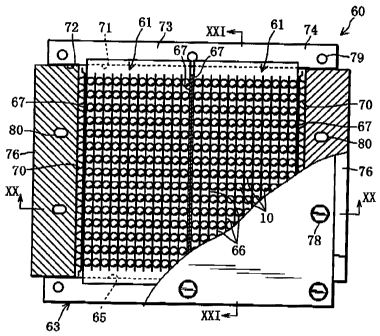
A solar battery module 60 of Embodiment 3 will be described with reference to
Figs. 18 to 27.
In the solar battery module 60, multiple solar battery cells 10 are divided
into,
6 for example, two groups to constitute two small tabular segment modules
61 and the
two segment modules 61 are installed and connected in series in a storage
casing 62
so that multiple solar battery cells 10 are assembled or separated in multiple
groups.
The solar battery cells 10 themselves are the same as the solar battery cells
in
=
Embodiments 1 and 2 and the same reference numbers are used in the following
explanation.
[00651
As shown in Figs. 18 to 21, the solar battery module 60 comprises two segment
modules 61 and a storage casing 62 forming a flat storage zone 66 for storing
the two
segment modules 61. The segment modules 61 are formed by arranging multiple
solar battery cells 10 in a matrix of multiple rows and multiple columns,
bonding
them to multiple conductive wires 66 using lead-free conductive adhesive to
connect
them in series and in parallel, and molding the entire structure in a
transparent
synthetic resin to a tabular form.
[00661
The segment modules 61 are serially arranged in the storage zone 65 within
the storage casing 62 and electrically connected by means of mechanical
pressure
from corrugated springs 70 (conductive connection members). In this
embodiment,
31
CA 02633368 2008-06-13
the solar battery module 60 having two segment modules 61 is described.
However,
the number of segment modules 61 installed in the storage casing 62 is not
restricted
to two. As the number of segment modules 61 is increased, the solar battery
module
60 can have a larger output.
6 [0067]
The segment module 61 will be described hereafter with reference to Figs. 22
to 26.
As shown in Fig.22, multiple solar battery cells 10 are arranged in a matrix
of
multiple rows and multiple columns with their conducting direction aligned in
the
column direction. Adjacent columns of solar battery cells 10 are spaced by a
distance approximately half of the diameter of the solar battery cells 10. The
distance can be larger or smaller, being determined on an arbitrary basis. For
example, columns are not spaced and the solar battery cells 10 in each row
abut
against each other.
[00681
Thin conductive wires 66 having a rectangular cross-section are provided
between multiple solar battery cells 10 in a row and multiple solar battery
cells 10 in
the adjacent rows, abutting against their positive and negative electrodes 5
and 6.
Connection conductors 67 having a larger rectangular cross-section than the
conductive wires 66 abut against the positive or negative electrode 5 or 6 of
multiple
solar battery cells 10 in the rows at the ends in the column direction. The
positive
and negative electrodes 5 and 6 of solar battery cells 10 are bonded to the
conductive
32
CA 02633368 2008-06-13
=
wires 66 or connection conductors 67 by a known conductive adhesive (such as
silver-epoxy resin) and heat-cured for fixing.
[0069]
In this way, multiple solar battery cells 10 in each row are connected in
6 parallel by a pair of conductive wires 66 or by a conductive wire 66 and
a connection
conductor 67. Multiple solar battery cells 10 in each column are connected in
series
by multiple conductive wires 66. Multiple solar battery cells 10 of the
segment
module 61 are connected in series and in parallel by multiple conductive wires
66
and two connection conductors 67. Then, a conductive connection mechanism
connecting in series the solar battery cells in each column and connecting in
parallel
the solar battery cells in each row is provided.
[0070]
The above multiple serially and parallel connected solar battery cells 10,
conductive wires 66, and connection conductors 67 are entirely molded in a
transparent synthetic resin (such as silicone resin) to a tabular form. The
connection conductors 67 at the ends are exposed from the edges of a synthetic
resin
plate 68. The synthetic resin plate 68 has cylindrical lens parts 69 covering
the
rows of solar battery cells 10 and flat holding parts 68a at the ends. The
cylindrical
lens parts 69 collect incident light to improve the output of the solar
battery cells 10.
[0071]
The solar battery module 60 having two segment modules 61 as described
above will be described hereafter with reference to Figs. 18 to 21.
33
CA 02633368 2008-06-13
The storage casing 62 is made of a transparent synthetic resin such as
polycarbonate resin, acrylic resin, and silicon resin. The storage casing 62
is formed
by superimposing a pair of upper and lower casing members 63, 63 having the
same
structure and fastening them with bolts. The easing members 63 each have a
recess
71 forming a half of the storage zone 66 and terminal mounting grooves 72
continued
from either end of the recess 71.
[00721
The casing member 63 has a pair of lands 73 (sidewalls) outsid.e the recess
71,
where for example a silicone rubber elastic coating 74 (for example a
thickness of
approximately 0.1 ram) covers approximately outer two thirds of the surface.
The
terminal mounting grooves 72 also have the same rubber coating 76 on the inner
surface. The solar battery module 60 is assembled by housing two segment
modules
61 in the recess 71 of the lower casing member 63, placing the upper casing
member
63, and clamping the holding parts 68a of the segment modules 61 at the ends
in the
row direction by the upper and lower lands 78.
[00781
Then, corrugated springs 70 and external terminals 76 are inserted in the flat
terminal mounting openings consisting of the upper and lower terminal mounting
grooves 72 at the ends in the column direction. Rubber packings 77 are
interposed
between the external terminal 76 and storage casing 62. Then, the upper and
lower
casing members 63 and the upper and lower casing member 63 and external
terminals 76 are fastened together by bolts. Here, bolts 78 are inserted in
bolt holes
34
CA 02633368 2008-06-13
79 and 80 together with for example fluororesin washers 78a and fastened to
nuts
78b together with underneath fluororesin washers78a.
100741
The bolt holes 80 of the external terminals 76 are elongated in the column
direction. The fastening position of the external terminals 76 can be adjusted
using
the bolt holes 80 so that the corrugated springs 70 provide a proper pressing
force.
In this way, with the connection conductors 67 making mechanical contact with
each
other in the center of the solar battery module 60, the two segment modules 61
are
electrically connected in series. The two segment modules 61 make mechanical
contact with and therefore electric connection to the external terminals 76
via the
corrugated springs 70 at the ends. The external terminals 76 protrude from the
storage casing 62 at the ends and serve as the positive and negative
electrodes of the
solar battery module 60 for external retrieval of output.
[0075]
16 Fig.27 shows an equivalent circuit to the mesh structure of the solar
battery
module 60. This equivalent circuit has the same efficacy as the equivalent
circuit of
Embodiment 2. Here, the positive terminal 81 and negative terminal 82 allows
for
external retrieval of electric power.
=
Gaps can be filled with a sealing material such as resins and rubbers where
necessary to seal the space in which the segment modules 61 are housed and
prevent
inflow of the ambient atmosphere.
10076]
CA 02633368 2008-06-13
In the solar battery module 60, two segment modules 61 are mechanically
connected in series by the corrugated springs 70 in the shared storage casing
62,
fastened and secured in position by the bolts 78 and nuts 78b, and sealed from
the =
ambient air by the rubber coatings 74 and 75 and paekings 77. The whole
storage
casing 62 can be disassembled to replace or retrieve the segment modules 61
for
reuse. When the module 60 is used as a window glass, the solar battery cells
10
spaced from each other provide excellent natural lighting and the space within
the
storage casing 62 provides heat insulation. When synthetic resin casing
members
68 are used, they will be lighter and not easily broken compared with glass.
[00771
The above described solar battery module has the following functions and
advantages.
(1) The connections between the segment modules 61 and between the
segment module 6/ and external terminal 76 are achieved by means of a
mechanical
pressing force from the corrugate springs 70; therefore, there is no need of
bonding by
solder or a jointing material. Then, there is no need of heating process for
electrical
connection. The segment modules 61, external terminals 76, or corrugated
springs
70 can be retrieved from the solar battery module 60 to use them in other
solar
battery modules. Multiple solar battery modules 60 can easily be connected in
series simply by contacting their external terminals 76 with each other.
[0078]
(2) The elastic conductive corrugated springs 70 are used to ensure electrical
36
CA 02633368 2008-06-13
connection. They absorb dimensional changes (expansion or contraction) in
association with temperature changes and mechanical shocks, preventing
excessive
stress on the solar battery cells 10.
(3) The distance between the columns in the segment module 61 can properly
6 be changed and the thickness of the conductive wires 66 can be determined
on an
.=
arbitrary basis. A solar battery module 60 or light emitting diode module or a
panel
consisting of two or more of them serving as a beautifully designed building
material
can be produced by properly selecting the proportion between natural lighting
(see-through) property and electric power generation.
[0079]
(4) The spherical solar battery cells 10 can use incident light in various
directions for electric power generation. When one or multiple solar battery
modules 60 are used as a window glass, the room light also can be used for
electric
power generation.
Partly modified embodiments of Embodiment 3 will be described hereafter.
[0080]
=
[1] The numbers of rows and columns of the matrix of multiple solar battery
cells 10 in the segment module 61 are given by way of example. The segment
module can have larger numbers of rows and multiple columns. The number of
=
segment modules 61 installed in the solar battery module 60 is not restricted
to two
and can be determined on an arbitrary basis. Multiple segment modules 61 are
arranged in multiple columns, not in one column, in the solar battery module
60. In
37
CA 02633368 2008-06-13
other words, multiple segment modules 61 are arranged in a matrix of multiple
rows
and multiple columns in a single solar battery module 60. In such a case, the
holding parts 68a of the segment module 61 can be eliminated so that the
segment
module 61 abuts against the inner surface of the storage zone 65.
[00811
12] With regard to the external terminals 76 of the solar battery module 60,
it
is advantageous for serially connecting multiple solar battery modules 60 that
one
(for example the positive electrode end) external terminal 76 protrudes
outside as
shown in the figure and the other (for example the negative electrode end)
external
terminal 76 is withdrawn in the terminal mounting opening and connectable to
one
(for example at the positive electrode end) of the external terminals 76 of an
adjacent
solar battery module 60.
[00821
[a] When the solar battery module 60 is used as a wall material that does not
16 require natural lighting or see-through property a light reflecting or
scattering plate
or sheet can be placed behind the solar battery cells 10. Light passing
between the
solar battery cells 10 is reflected behind the solar battery cells 10 and
increase the
output of the solar battery cells 10 in the solar battery module 60.
Alternatively,
light reflected forward increases brightness in a light emitting diode module.
(0083]
[4] Applications include solar battery modules integrated with a building
material such as a roof, skylight, window, curtain wall, facade, eave, and
looper,
38
CA 02633368 2008-06-13
outdoor light emitting diode displays, and functional units on advertising
pillars,
automobiles, aircraft, and boats for solar electric power generation or
display or for
both.
[0084]
[5] Various sensors, signal receiver, signal transmitter, ac/dc converter,
frequency converter, logic circuits, and CPU and peripheral circuitry can be
installed
on the lands 73 of the casing members 63 to control the input/output of the
solar
battery module or light emitting diode module.
INDUSTRIAL APPLICABILITY
10085]
The light receiving or light emitting semiconductor module of the present
invention is effectively used in solar battery panels or light emitting diode
displays
and illumination apparatuses.
89