Note: Descriptions are shown in the official language in which they were submitted.
CA 02633376 2008-06-16
1
DESCRIPTION
Process for Manufacturing a Seamless Tube
Technical Field
This invention relates to a process for manufacturing a seamless tube.
Specifically, it relates to a process for manufacturing a seamless tube
comprising
piercing a billet in a piercer (a skew rolling mill) to produce a hollow
shell.
Background Art
Seamless tube is usually manufactured by the Mannesmann plug mill process
or the Mannesmann mandrel mill process. In order to manufacture seamless tube
by
io such a process, first, a solid rod-shaped billet (referred to in this
description simply as
a billet) is introduced into a heating furnace and heated therein to a
predetermined
temperature. The billet is then removed from the heating furnace and is rolled
for
piercing in a piercer to produce a hollow shell. The hollow shell is then
rolled for
elongation using a plug mill or a mandrel mill or a similar rolling mill in
which
primarily the wall thickness of the hollow shell is reduced. Thereafter, it is
rolled for
sizing using a reducing mill such as a sizer or a stretch reducer in which
primarily the
outer diameter thereof is reduced to manufacture a seamless tube having
desired
dimensions.
In Patent Document 1, the present inventors disclosed an invention in which a
ao billet is pierced using a piercer comprising skew rolls and grooved disk
rolls each
having an optimized roll shape, thereby making it possible to perform piercing
with
high efficiency without the occurrence of miss-rolling (a state in which the
advance
of the material being rolled stops) while suppressing an increase in the outer
diameter
of the bottom portion of the resulting hollow shell under such conditions that
the
expansion ratio Exp (outer diameter of the hollow shell/outer diameter of the
billet) is
at least 1.15.
In Patent Document 2, the present inventors also disclosed an invention in
which piercing of a billet is performed while controlling the rotary forging
effect and
preventing the occurrence of internal surface flaws by optimizing the ratio of
the
CA 02633376 2008-06-16
2
rotational frequency (rotating speed) of a billet in the steady state region
up to the tip
of a plug (as will be explained while referring to the graph in Figure 1, this
is the
region from LE2 onwards in which the speed of advance of the billet becomes
roughly constant after the start of piercing) to the rolling reduction of the
outer
diameter of the billet depending on the ratio between the diameter of the skew
rolls
of a piercer at its inlet and the diameter of the gorge portion of the skew
rolls, the
rotational frequency of billet being determined by the predetermined roll
inclination
angle, the piercing ratio, and the piercing efficiency.
Patent Document 1: JP 3021664 B2
Patent Document 2: WO 2004/103593
Disclosure of Invention
Actual piercing by a piercer may be applied to a billet made of a continuously
cast material having center segregation or porosity, or to a stainless steel
having poor
hot deformability, for example. In this case, an increase in the outer
diameter of the
1s bottom portion of the resulting hollow shell can be suppressed if piercing
is
performed under rolling conditions which are suitably determined based on the
invention disclosed in Patent Document 1. However, even in accordance with
such
invention, it is sometimes not possible to entirely eliminate the occurrence
of internal
surface flaws and thickness deviations (deviations in wall thickness in a
tube's
circumferential direction) in the top portion of the resulting hollow shell.
In the invention disclosed in Patent Document 2, the rotary forging effect in
the midportion of a billet can be suppressed by using disk rolls in which the
surface
of each roll which contacts the material being rolled has a cross-sectional
shape with
a semicircular groove. In this case, however, if the rotational frequency of a
billet is
small or the rolling reduction of the outer diameter of a billet is small,
slippage
between the skew rolls and the billet increases in a piercer, and the rotary
forging
effect at the time of gripping of the billet by the rolls ends up increasing.
In addition,
the frictional resistance between a plug of the piercer and the billet
increases, thereby
increasing the shearing deformation and causing the occurrence of internal
surface
flaws. Moreover, oscillation of the billet increases in a transient (non-
steady state)
CA 02633376 2008-06-16
3
region as the billet is gripped by the skew rolls, and thickness deviations of
the top
portion of the resulting hollow shell worsen. Furthermore, in the invention
disclosed
by Patent Document 2, when the expansion ratio is large, the outer diameter of
the
bottom portion of the resulting hollow shell may increase under some
conditions of
the diameter of the disk rolls and the rotational frequency of the billet. An
increase
in the outer diameter of the bottom portion of a hollow shell causes, when the
hollow
shell is subsequently rolled through grooved rolls in a mill such as a mandrel
mill, an
increase in the load to be applied to the grooved rolls by over-filling of the
material
being rolled into roll gaps between groove flange portions and a decrease in
the yield.
Thus, in the inventions disclosed in Patent Document 1 or Patent Document 2,
a hollow shell which is produced from a billet in a piercer may have internal
surface
flaws or thickness deviations found in its top portion, or an increase in the
outer
diameter occurring in its bottom portion, due to the properties inside the
billet or its
thermal deformability or resulting from the rotational frequency, the
reduction ratio
of the outer diameter, and other parameters of the billet when using disk
rolls as tube
guides in the piercer, and it was sometimes not possible to produce a hollow
shell of
high quality over its entire length from its top portion to its bottom
portion.
In the past, a hollow shell was made freed of internal surface flaws and
thickness deviations over its entire length by cutting off its top portion or
by repair of
the top portion, but such a measure incontrovertibly increases the
manufacturing
costs.
The present invention is a process for manufacturing a seamless tube
characterized by comprising subjecting a billet to piercing to produce a
hollow shell
while rotating and advancing (translating) the billet, using a pair of cone-
shaped
skew rolls having a gorge portion and disposed opposite each other around a
pass
line, a pair of grooved disk rolls, and a plug disposed along the pass line
between the
skew rolls and the disk rolls, under such conditions that the ratio (Dg/d) of
the
diameter Dg of the gorge portion of the skew rolls and the outer diameter d of
a billet
which is a material being rolled, the ratio (Dd/d) of the diameter Dd of the
groove
3o bottom of the disk rolls and the outer diameter d of the billet, and the
ratio (Dd/Dg)
of the diameter Dg of the gorge portion of the skew rolls and the diameter Dd
of the
CA 02633376 2008-06-16
4
groove bottom of the disk rolls satisfy either the following Equations (1),
(2), and (3)
or the following Equations (1), (2), and (4), the skew rolls have an inlet
face angle 01
which satisfies the following Equation (5), and the square root of the product
(Ns x
Df) 5 of the rotational frequency Ns of the billet in a transient (non-steady
state)
region when the billet is gripped by the skew rolls and the reduction ratio Df
of the
outer diameter of the billet satisfies the following Equation (6) which is a
function of
the ratio (Dg/D 1) of the diameter in the gorge portion of the skew rolls and
the
diameter D1 of the skew rolls at the location where they contact the billet in
the inlet
thereof.
3<Dg/d7 .... (1)
9Dd/d16 .... (2)
in the case of an expansion ratio Exp _ 1.15
2 < Dd/Dg <_ 3 .... (3)
in the case of an expansion ratio Exp < 1.15
1.5 _ Dd/Dg <_ 3 .... (4)
2.5 _< 01 <_ 4.5 .... (5)
0.46 x (Dg/D1) - 0.31 <(Ns x Df) 5< 1.19 x (Dg/D 1) - 0.95 .... (6)
wherein Ns = Ld x Vr/(0.5 x n x d x Vf) and Df = (d - dp)/d, where Vf is the
smallest
speed of the billet in the direction of its advance in a transient region when
the billet
is gripped by the skew rolls, Vr is the average speed in the circumferential
direction
of the billet in the transient region when the billet is gripped by the skew
rolls, dp is
the roll gap of the skew rolls at the tip of the plug, and Ld is the length
along the pass
line from the point in which the front end of the billet gets to contact with
the skew
rolls to the tip of the plug, the length being determined in the manner of two
dimensional geometry in a state of the skew rolls having an inclination angle
of zero.
In the present invention, a "transient region" when a billet is gripped by
skew
rolls means the period from the time when the billet contacts the tip of a
plug in a
piercer until the time when the front end of the billet disengages from the
skew rolls.
In a manufacturing process for a seamless tube according to the present
invention, the frequency of rotary forging and shear deformation occurring in
a
transient region at the stage of billet gripping during piercing are
suppressed. As a
CA 02633376 2008-06-16
result, in the top portion of a hollow shell produced by piercing, the
occurrence of
internal surface flaws caused by the rotary forging effect and/or shear
deformation
can be prevented, and a worsening of thickness deviation can also be
prevented,
thereby preventing miss-rolling such as incomplete billet gripping or troubles
in tube
5 bottom withdrawal. In addition, an increase in the outer diameter of the
bottom
portion of a hollow shell can be prevented, and a hollow shell having a high
quality
over its entire length from its top portion to its bottom portion can be
reliably
manufactured.
Thus, in accordance with the present invention, when a billet is pierced with
a
io piercer to produce a hollow shell, the occurrence of rolling defects during
piercing in
the transient region of both the top portion and the bottom portion of the
hollow shell
can be reduced or eliminated, leading to a tremendous effect of increasing the
yield
and productivity of hollow shells. The effect of this invention of reducing or
eliminating rolling defects in the transient rolling region of both the top
portion and
1s the bottom portion of a hollow shell could not possibly be achieved based
on the
inventions disclosed in either Patent Document 1 or Patent Document 2 which
gives
no consideration at all to improving rolling defects in the transient rolling
regions of
both the top portion and the bottom portion of a hollow shell.
Brief Description of the Drawings
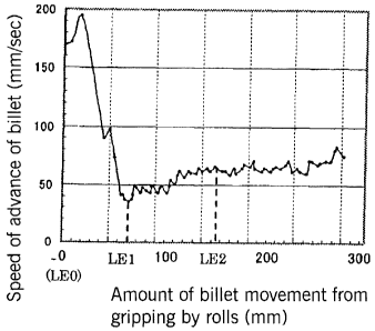
20 Figure 1 is a graph showing an example of the relationship between the
speed
of advance of a billet (mm/sec) which is the result of measurement of the
speed of
advance of a billet along a pass line and the amount of movement of a billet
(mm)
from gripping by rolls which shows the distance of movement of the billet from
the
position where the billet contacts skew rolls.
25 Figure 2 is a plan view schematically showing the structure of a piercer.
Figure 3 is an elevation schematically showing the structure of a piercer.
Figure 4 is a transverse cross-sectional view schematically showing the state
during piercing with a piercer.
Figure 5 is a transverse cross-sectional view schematically showing the state
3o during piercing with a piercer.
CA 02633376 2008-06-16
6
Figure 6 is an explanatory view showing the shape of a plug.
Figure 7 is a graph showing the results of a piercing test.
List of Reference numerals
0: piercer, 1: skew roll, 1 a: gorge portion, 1 b: inlet surface, i c: outlet
surface,
2: plug, L 1: rolling portion, L2: reeling portion, 3: billet, 4: drive
mechanism,
G: disk roll
Best Mode for Carrying Out the Invention
Below, the best mode for carrying out a process for producing a hollow shell
according to the present invention will be explained in detail while referring
to the
io accompanying drawings.
First, new findings which are the basis for the present invention will be
explained.
In order to investigate the cause of the more frequent occurrence of internal
surface flaws in the front end portion than in the mid-portion of a hollow
shell in the
is lengthwise direction, the speed of advance of a billet at the time of
piercing (the
speed in the rolling direction), which is closely connected to the rotary
forging effect
in piercing, and the rotational speed of a billet in the circumferential
direction during
piercing are investigated.
A billet made of S45C with an outer diameter of 70 mm is heated to 1200 C
20 and subjected to piercing with a piercer having skew rolls and a plug.
Specifically,
piercing of the billet is carried out under conditions in which the
inclination angle of
the skew rolls of the piercer is 10 , the roll gap in the gorge portions of
the skew rolls
is 61 mm, and the plug forward amount, which is the distance in the axial
direction
from the skew rolls to the tip of the plug, is 38 mm, to produce a hollow
shell with an
25 outer diameter of 75 mm and a wall thickness of 6 mm.
To determine the speed of advance of a billet during piercing, a graduated
plate is installed along the pass line on the inlet side of a piercer, the
rear end of the
billet and the graduated plate are photographed with a video camera, and based
on
the photographed image data, the speed of advance of the billet is calculated
from the
3o distance moved by the rear end of the billet per unit time.
CA 02633376 2008-06-16
7
To determine the rotational speed of the billet, a pin which serves as a mark
is
driven into the rear end surface of the billet in the vicinity of the outer
peripheral
edge, the movement in the circumferential direction of the pin in the rear end
surface
of the billet is photographed with a video camera during piercing, and based
on the
photographed image data, the rotational speed based on the amount of movement
of
the billet is calculated from the amount of movement in the circumferential
direction
of the pin per unit time.
Figure 1 is a graph showing one example of the relationship between the
speed of advance of a billet (mm/sec), which is the calculated speed of
advance of a
io billet along a pass line, and the amount of movement of the billet (mm)
from the time
of gripping by rolls, which indicates the amount of movement of the billet
from the
position where the billet contacts skew rolls.
As shown in the graph of Figure 1, the speed of advance of the billet abruptly
decreases as the front end of the billet contacts the skew rolls and is
gripped thereby
(while the amount of billet movement changes from LEO to LE 1). When the front
end of the billet reaches the location of the tip of the plug and begins to be
pierced (at
the point of amount of billet movement = LE 1), the speed of advance of the
billet
reaches a minimum. As the billet continuously undergoes piercing, it is
gradually
stably gripped, and the speed of advance of the billet gradually increases
(while the
2o amount of billet movement changes from LE 1 to LE2). Then, piercing
proceeds in a
steady state in which the speed of advance is nearly constant (after the point
of
amount of billet movement = LE2).
In contrast, the rotational speed of the billet is roughly constant in the
period
from when the billet contacts the skew rolls until piercing reaches the steady
state.
The present inventors made the following findings from the results shown in
the graph of Figure 1. In the period from the time when a billet is gripped by
the
skew rolls and begins to be pierced by the plug until the time when piercing
reaches a
steady state, i.e., in the transient region from LE1 to LE2 in Figure 1, the
speed of
advance of the billet is lower than the speed of advance in the steady state
region, and
the rotational speed of the billet is roughly constant throughout. Namely, it
was
found that when a billet is gripped by the skew rolls, slippage in the
direction of
CA 02633376 2008-06-16
8
advance of the billet increases in the transient region. The phenomenon shown
in the
graph of Figure I in which the speed of a billet varies in this manner is a
significant
finding which was totally unknown to those skilled in the art before the
present
application.
The phenomenon shown in the graph of Figure 1 in which the speed of a billet
varies in this manner is expected to cause problems such as the following.
In the transient region, the frequency (number of occurrences) of rotary
forging per unit length of movement in the direction of advance of the billet
is larger
than in the steady state region, and the rotary forging effect becomes marked.
In
io addition, due to a slower speed of advance of the billet, the redundant
shear
deformation due to the frictional force between the billet and the plug
increases. Due
to a synergistic effect of these events, piercing of a billet in its top
portion becomes
unstable, and the billet produces a markedly increased oscillation at the time
of
piercing of the top portion of the billet. As a result, in the front end
portion of the
resulting hollow shell, there is much occurrence of internal surface flaws,
and
thickness deviations also occur markedly.
The presence of this transient region is unavoidable. The present inventors
realized that it is essential to find conditions for suppressing the rotary
forging effect
and the redundant shear deformation, which unavoidably occur in the transient
2o region, to a level such that they do not cause internal surface flaws at
the front end
portion of a hollow shell.
It is known that the rotary forging effect in a steady state region can be
suppressed if the reduction ratio Df of the outer diameter of a billet is
decreased or if
the frequency of rotary forging N in a steady state region, which is a
function of the
previously set roll inclination angle P, billet diameter, and piercing ratio,
is
decreased,.
However, merely decreasing the reduction ratio Df of the outer diameter of a
billet and the frequency of rotary forging N in the steady state region does
not solve
the above-described problem occurring in the transient region shown in the
graph of
3o Figure 1.
The present inventors discovered that conditions which can suppress the rotary
CA 02633376 2008-06-16
9
forging effect and the redundant shear deformation, which unavoidably occur in
the
transient region of piercing, to an extent that they do not cause internal
surface flaws
to occur in the front end portion of the resulting hollow shell can be defined
by using
the square root of the product of the rotational frequency Ns of a billet in
the
transient region and the outer diameter reduction ratio Df of the billet (Ns x
Df) 5 as
an index together with the ratio (Dg/D 1). When the square root of the product
of the
rotational frequency Ns of a billet in the transient region and the outer
diameter
reduction ratio Df of the billet (Ns x Df)"5 and the ratio (Dg/D 1) as
indices, the
qualitative significance of each index is as follows.
If the outer diameter reduction ratio Df of a billet becomes small, stable
billet
gripping is impeded and slippage easily occurs. As a result, shear deformation
caused by the frictional force between the surface of the plug and the
internal surface
of the billet increases, and internal surface flaws develop due to this shear
deformation. The propulsive force exerted by the skew rolls is influenced by
their
shape. Therefore, the shear deformation caused by the frictional force between
the
surface of the plug and the internal surface of the billet is also influenced
by the
magnitude of the ratio (Dg/D1) of the diameter D1 of the skew rolls at the
location in
the inlet where they contact the billet and the diameter Dg in the gorge
portion of the
skew rolls. As stated above, if slippage increases, piercing of a billet
becomes
unstable, and the billet oscillates in the circumferential direction, thereby
worsening
the thickness deviations of the top portion of the resulting hollow shell.
If the rotational frequency Ns of the billet in the transient region is made
too
small by varying the inclination angle of the skew rolls, for example, the
amount of
movement of the billet advancing in the rolling direction during the period in
which a
half rotation of the billet occurs in the transient region increases,
resulting in an
increased reduction in wall thickness per unit rotation of the billet by the
action of the
skew rolls and the plug in the transient region. As a result, it becomes easy
for
slippage to occur between the skew rolls and the billet. Another method for
decreasing the rotational frequency Ns of the billet in the transient region
is to
increase the inlet face angle 81 of the skew rolls.
The magnitude of the ratio (Dg/D 1) of the diameter D 1 of the skew rolls at
the
CA 02633376 2008-06-16
location in the inlet where they contact the billet and the diameter Dg of the
skew
rolls in the gorge portion, the ratio indicating the shape of the skew rolls,
influences
the propulsive force exerted by the skew rolls, and ultimately it influences
the
occurrence of slippage and shear deformation which is produced by the
frictional
5 force between the surface of the plug and the internal surface of the
billet.
Next, a piercer which is used in this embodiment will be described.
Figure 2 is a plan view schematically showing the structure of a piercer 0.
Figure 3 is an elevation schematically showing the structure of the piercer 0.
Figures
4 and 5 are transverse cross-sectional views schematically showing the state
in the
Io course of piercing by the piercer 0.
In Figures 2 - 5, each skew roll 1 has a gorge portion la having a roll
diameter
Dg at its midportion, an inlet surface lb which forms a generally truncated
cone
having an outer diameter which decreases towards the end of the inlet
(entrance) side
from the gorge portion 1 a, and an outlet surface 1 c which forms a generally
truncated
cone having an outer diameter which increases towards the end of the outlet
(exit)
side from the gorge portion 1 a. As a whole, each skew roll is formed in the
shape of
a cone.
Each skew roll 1 is disposed so that its roll axis shown by a single-dash
chain
line intersects the pass line X-X at an angle y.
As shown in Figure 3, the skew rolls 1, 1 are disposed so as to have a reverse
angle of inclination (3 with respect to the pass line X-X. Each skew roll 1 is
rotatably
driven by a drive mechanism 4.
As shown in Figure 4, a pair of disk rolls G which are tube guides are
disposed opposite each other between the skew rolls 1, 1. The disk rolls G are
guide
rolls having contact surfaces with the billet having a cross-sectional shape
which is a
semicircular groove.
A plug 2 is disposed between the skew rolls 1, 1 along the pass line X-X.
Figure 6 is an explanatory view showing the shape of the plug 2.
As shown in this drawing, the plug 2 generally has a tip portion r. The plug 2
is in the shape of an artillery shell with a maximum outer diameter of Dp and
including a rolling portion L I with a conical shape and a longitudinal cross
section
CA 02633376 2008-06-16
11
defined by a curve with a radius R and a reeling portion L2. The proximal
(basal)
end of the plug 2 is secured to the distal end of a mandrel bar M, and the
proximal
end of the mandrel bar M is supported by an unillustrated thrust block
mechanism
which can move in the axial direction.
In this embodiment, the plug 2 used for piercing has a shape such that the
ratio
(r/d) of the radius of curvature r of the tip of the plug 2 to the diameter d
of the billet
3 is at least 0.085 to at most 0.19, and the ratio (R/L 1) between the length
L 1 of the
rolling portion of the plug 2 and the radius of curvature R of the rolling
portion of the
plug 2 is at least 1.5.
If the ratio (r/d) is less than 0.085, the service life of the plug 2 is
greatly
decreased due to thermal effects, while if the ratio (r/d) is greater than
0.19, slippage
in the direction of advance of the billet 3 becomes large. Similarly, if the
ratio
(R/L1) is less than 1.5, slippage in the direction of advance of the billet 3
becomes
large.
Next, the state in which piercing is carried out using this piercer 0 will be
explained.
A billet 3 which has been heated to a predetermined temperature is transported
on a feed table (not shown) of the piercer 0 and is gripped by the skew rolls
1, 1
along the pass line X-X.
The billet 3 gripped by the skew rolls 1, 1 advances in the direction shown by
the hollow arrows in Figures 2 and 3 while rotating until it reaches the tip
of the plug
2. During this advance, the billet 3 undergoes working by the skew rolls 1, 1
to
decrease its outer diameter.
Next, the billet 3 is pierced at its center by the plug 2, and undergoes
working
to form a wall thickness between the plug 2 and the skew rolls 1, 1 every half
rotation of the billet. As a result, it undergoes piercing to form a hollow
shell H.
In this embodiment, when carrying out piercing in this manner, in order to
suppress an increase in the outer diameter of the bottom portion of the
resulting
hollow shell, which causes problems when the hollow shell is rolled in a
downstream
3o rolling mill, the skew rolls 1 and disk rolls G which are used are selected
such that
(a) the ratio (Dg/d) of the diameter Dg in the gorge portion 1 a of the skew
CA 02633376 2008-06-16
12
rolls 1, 1 to the outer diameter d of the billet 3,
(b) the ratio (Dd/d) of the diameter Dd in the groove bottom of the disk rolls
G which are tube guides to the outer diameter d of the billet 3, and
(c) the ratio (Dd/Dg) between the diameter Dg in the gorge portion 1 a of the
s skew rolls 1, 1 and the diameter Dd in the groove bottom of the disk rolls G
satisfy either the following Equations (1), (2), and (3) or the following
Equations (1), (2), and (4), and such that the inlet face angle 91 of the skew
rolls 1, 1
satisfies the following Equation (5):
3Dg/d_7 .... (1)
9Dd/d<_16 .... (2)
when the expansion ratio Exp _ 1.15,
2 < Dd/Dg _ 3 .... (3)
when the expansion ratio Exp < 1.15,
1.5 _ Dd/Dg < 3 .... (4)
2.5 _< 01 < 4.5 .... (5)
The reasons for the limitations of Equations (1) - (5) will be explained
below.
If the ratio (Dg/d) in Equation (1) is smaller than 3, the service life of
bearings
will decrease due to inadequate strength of the bearings. If the ratio (Dg/d)
exceeds
7, equipment costs will increase in order to suppress an increase in the outer
diameter
of the bottom portion of the hollow shell resulting from an increase in the
wall
thickness of the bottom portion of the billet. Therefore, in this embodiment,
the ratio
(Dg/d) is limited to at least 3 and at most 7.
If the ratio (Dd/d) in Equation (2) is less than 9, the resulting hollow shell
H
will suffer troubles during tube bottom withdrawal and have an increased outer
diameter in the bottom portion. If the ratio (Dd/d) exceeds 16, the hollow
shell H
will have a large number of exterior surface flaws and an increased outer
diameter of
the bottom portion, and the diameter of the disk rolls G becomes large whereby
the
overall mill becomes large in size and equipment costs increase. Therefore, in
this
embodiment, the ratio (Dd/d) is limited to at least 9 and at most 16.
If the ratio (Dd/Dg) in Equation (3) is 2 or less, in the case of piercing at
an
expansion ratio of at least 1.15, the resulting hollow shell H will suffer
troubles in
CA 02633376 2008-06-16
13
tube bottom withdrawal and have an increased outer diameter in the bottom
portion.
If the ratio (Dd/Dg) exceeds 3, in the case of piercing at an expansion ratio
of at least
1.15, the hollow shell H will have exterior surface flaws and an increased
outer
diameter in the bottom portion. Therefore, in this embodiment, when the
expansion
ratio is at least 1.15, the ratio (Dd/Dg) is limited to greater than 2 to at
most 3.
If the ratio (Dd/Dg) in Equation (4) is at least 1.5, in the case of piercing
at an
expansion ratio of less than 1.15, there are no rolling problems in the
subsequent mill
due to an increase in the outer diameter of the bottom portion of the
resulting hollow
shell H, and the ratio may be determined from the standpoint of stability of
piercing
io (thickness deviation and ease of billet gripping by rolls). If the ratio
(Dd/Dg)
exceeds 3, in the case of piercing at an expansion ratio of less than 1.15,
the hollow
shell H will have outer surface flaws and an increased outer diameter of the
bottom
portion. Therefore, in this embodiment, when the expansion ratio is less than
1.15,
the ratio (Dd/Dg) is limited to at least 1.5 to at most 3.
If the inlet face angle 01 of the skew rolls 1 in Equation (5) is either
greater
than 4.5 or less than 2.5 , the ease of gripping of a billet 3 by the skew
rolls 1 will
worsen. Therefore, in this embodiment, the inlet face angle 01 of the skew
rolls 1 is
limited to at least 2.5 to at most 4.5 .
In this embodiment, a billet 3 is pierced using a piercer 0 comprising skew
2o rolls 1, a plug 2, and disk rolls G with shapes defined by Equations (1) -
(5) under
conditions of rotational frequency of the billet 3 and the outer diameter
reduction
ratio of the billet 3, which are the settings for the rolls, satisfying
Equation (6):
0.46 x (Dg/D 1) - 0.31 <_ (Ns x Df) 5< 1.19 x (Dg/D1) - 0.95 .... (6)
In Equation (6), Ns = Ld x Vr/(0.5 xTu x d x Vf) and Df = (d - dp)/d, wherein
Vf indicates the smallest speed of the billet in the direction of its advance
in the
transient region as the billet is gripped by the skew rolls, which can be
determined,
for example, by collecting piercing data, using these data to approximate the
speed of
the billet in the axial direction in the transient region as the billet is
gripped by the
skew rolls by the least squares method, and employing the minimum speed in the
3o direction of advance of the billet found by this approximation, Vr
indicates the
average speed in the circumferential direction of the billet in the transient
region
CA 02633376 2008-06-16
14
when the billet is gripped by the skew rolls, dp indicates the roll gap of the
skew rolls
at the tip of the plug, and Ld is the length from the position in which the
front end of
the billet is initially gripped by the skew rolls to the tip of the plug.
In order to solve the problems of shear deformation, thickness deviation,
s bottom blockage, and an increase in the outer diameter of the bottom portion
which
may develop depending upon the settings for the skew rolls 1, the present
inventors
performed a piercing test. In the test, a material which was a billet 3 with
an outer
diameter of 70 mm cut from the center of a larger billet 3 with an outer
diameter of
310 mm made of a continuously cast carbon steel containing 0.2 mass % C and a
io material made of steel containing 13 mass % Cr with an outer diameter of 70
mm
taken from the center of a sample with a diameter of 225 mm prepared by
continuous
casting following by blooming were heated to 1200 C and subjected to piercing
under the conditions shown in Table 1 using a piercer 0 satisfying above-
described
Equations (1) - (5). The results of the piercing test are shown in the graph
of Figure
15 7.
Table 1
-------Dg -------- ~ 00 mm
-400
1mm
ao 30
-_j--------------------------
-------
d ~ 70mm
-a------------~ 1.06J ------------:1 0.17-0.59
In the graph of Figure 7, the black circles indicate the case in which there
was
25 occurrence of at least one of internal surface flaws caused by shear
deformation, a
worsening of the thickness deviation to at least 7 %, incomplete billet
gripping or
troubles of tube bottom withdrawal, and an increase in the outer diameter of
the
bottom portion exceeding 5 %. The black triangles indicate the case in which
internal surface flaws caused by rotary forging and/or shear deformation
occurred.
so The hollow circles indicate the case in which a hollow shell could be
produced
CA 02633376 2008-06-16
without any problems.
From the results shown in the graph of Figure 7, it can be seen that when the
relationship defined by { 0.46 x (Dg/D1) - 0.31 }<_ (Ns x Df) 5_< { 1.19 x
(Dg/D 1) -
0.951 is satisfied, a hollow shell can be produced without problems.
5 Thus, if the value of (Ns x Df) 5 in Equation (6) is less than {0.46 x
(Dg/D 1) -
0.31 }, problems such as the occurrence of internal surface flaws and
thickness
deviations, bottom blockage, and an increase in the outer diameter of the
bottom
portion of the resulting hollow shell develop due to an increase in the shear
deformation of the top portion. On the other hand, if the value of (Ns x
Df)o.s
io exceeds {1.19 x(Dg/D1) - 0.95}, the occurrence of internal surface flaws
due to the
rotary forging effect and shear deformation cannot be suppressed. Accordingly,
in
this embodiment, the value of (Ns x Df) 5 is limited to at least 10.46 x
(Dg/D 1) -
0.311 to at most {1.19 x(Dg/D 1) - 0.951.
Thus, according to this embodiment, when manufacturing a seamless tube by a
15 process comprising piercing a billet with a piercer to produce a hollow
shell, it
becomes possible (a) to suppress an increase in the outer diameter during
piercing,
(b) to suppress the rotary forging effect and shear deformation in the top
portion,
thereby preventing internal surface flaws from occurring in the top portion of
the
hollow shell, and (c) to reduce thickness deviations in the top portion of the
hollow
shell. Therefore, according to this embodiment, a hollow shell having high
quality
with respect to dimensions and internal properties over its entire length can
be
produced with certainty.
Example 1
The present invention will be explained more specifically with reference to
examples.
A billet with an outer diameter of 70 mm was cut from the center of a billet
of
a continuously cast carbon steel containing 0.2% C having an outer diameter of
225
mm. The cut billet was heated to 1200 C and subjected to piercing under the
conditions shown in Table 2. The results of piercing are compiled in Table 3.
CA 02633376 2008-06-16
16
Table 2
Dg 400 mm
Dd 1100 mm
Exp 1.03 - 1.28
61 3
d 70 mm
Dg/D 1 1.06 - 1.28
(NsxDf)05 0.15-0.48
Table 3
Internal Incom- troubles in Percent Increase in
o s surface plete bottom thickness bottom
Exp Dg/D1 (Np x Df) flaws i in withdrawal deviation outer
~ pp g diameter
1.03 1.06 0.25 0 0 0 0 0 This invention
1.03 1.1 0.3 0 0 0 0 0 This invention
1.25 1.19 0.35 0 0 0 0 0 This invention
1.16 1.23 3 0 0 0 0 0 This invention
1.03 1.06 0.15 ND X ND ND ND Comparative
1.25 1.23 0.2 0 0 0 X X Comparative
1.12 1.28 0.25 0 0 X 0 ND Comparative
1.03 1.14 0.48 X O 0 0 O Com arative
ND: not determinable
The mark "0" in Table 3 indicates that piercing could be performed without
any problems, and the mark "X" indicates the occurrence of any of incomplete
billet
gripping, troubles in tube bottom withdrawal, thickness deviations, or an
increase in
the bottom outer diameter.
Concerning the internal surface flaws in Table 3, the case in which at least 2
flaws were observed in a region of 20 - 200 mm in length from the top of a
hollow
shell is indicated by an X.
Concerning the percent thickness deviation in Table 3, in a region of 20 - 200
mm in length from the top of a hollow shell, the wall thickness was measured
at 8
points in the circumferential direction at a pitch of 5 mm in the lengthwise
direction
using a micrometer, and using the actually measured wall thickness, the
percent
thickness deviation in the circumferential direction was calculated at each
lengthwise
CA 02633376 2008-06-16
17
position as {(maximum wall thickness - minimum wall thickness)/average wall
thickness at eight points I. The percent wall thickness deviations at all the
positions
in the lengthwise direction were averaged, and the average percent thickness
deviation was used for evaluation. A percent thickness deviation of 6 % or
greater is
indicated by an X.
With respect to the evaluation of incomplete billet gripping and troubles in
tube bottom withdrawal in Table 3, the case in which at least one such defect
occurred in 100 pierced tubes is indicated by an X. Concerning the percent
bottom
outer diameter increase in Table 3, the case in which the percentage of the
maximum
io diameter of the bottom portion with respect to the average value of the
outer diameter
of the middle portion was 6 % or greater is indicated by an X.
From the results shown in Table 3, it can be seen that by satisfying not only
Equations (1) - (5) but also Equation (6), a hollow shell can be produced by
piercing
in a piercer while suppressing any of internal surface flaws of the top
portion,
is incomplete billet gripping, troubles in tube bottom withdrawal, the percent
thickness
deviation, and an increase in the outer diameter of the bottom portion to a
level
which cause substantially no problems.