Note: Descriptions are shown in the official language in which they were submitted.
CA 02633758 2008-05-02
,06 842 202.1-2311 Apri122, 2008
~
NEQ LAB Holding Inc., Starikovsky, Andrey Yurievich EPAD-98736.0
The method of initiation of ignition, intensification of combustion or
reforming
of fuel-air and fuel-oxygen mixtures
Field of the invention
This invention relates to mechanical engineering, and more particularly, to
power
. 10 engineering industry and engine-building, and is designed for
intensification of chemical
processes in the combustible mixture using pulsed periodic nanosecond high-
voltage
discharge in internal combustion engines of any kind, including (without
limitation)
afterburners, combustors of detonation engines, jet engines and gas turbine
engines, in power
burners and reformers.
Background of the invention
There are several methods aimed at intensification of combustible mixtures
combustion in internal combustion engines combustion chambers. Most widely-
spread
I
methods are those using preliminary preparation of combustible mixture,
including electric-
discharge treatment of air, inject fuel treatment with electromagnetic field,
methods based on
improvement of electric spark ignition of combustible mixtures, and in the
latter case the
result is achieved by way of modification of electric ignition spark plugs
design (SU No.
1728521, SU No.1838665, RU 2099550).
There is a known method of combustion processes activation allowing to
increase
effectiveness and uniformity of combustible mixture combustion in internal
combustion
engines, to reduce combustion induction time, ignition temperature and to
provide controlled
increase of combustion front propagation rate (RU No. 94028477,
F02M25110,1996). Such a
CA 02633758 2008-05-02
~
2
~
method consists in treatment of air fed to the internal combustion engine by
the system of
volumetric self-maintained discharges with set-up parameters.
Disadvantages of known methods are the requirement for modifications in the
engine
design and imperfection of usual electric spark ignition method for
combustible mixture
ignition which does not provide complete combustion of mixture in chambers.
The nearest prior art to the present invention is the method of combustible
mixture
ignition using streamer spaxk plug (RU Na.2176122, HO1T13120, 2001). In this
invention
~ streamer phenomenon is used for increase of ionization rate in the zone of
generation of main
electric discharge by means of creation of favourable conditions for stable
spark formation.
The solution of this aim consists in placing voltage between the plug centre
and side
electrodes which provides ionization of space between them. At that at the
centre electrode
insulator streamer is formed, ionization field in the zone limited by ground
starting electrode
circuit is amplified, and electric discharge between the centre electrode and
the spark-
receiving surface of the ground electrode main part is formed. This invention
provides
stability of operation of internal combustion engines, including those used in
motorcycle
. systems, in all possible modes of operation.
The above prior art is of limited application as it is intended for use only
in gasoline
engines (car and motorcycle engines).
Disclosure of the invention
Fuel oxidation reaction proceeds by a branched-chain mechanism.
From the theory of branched radical-chain reactions the following is known:
1. Elementary steps. The characteristic feature of chain reactions is that
chemical
agents consumption and final products formation occur via sequence of
recurrent elementary
steps at which source material particles-active species reaction results in
formation of the
CA 02633758 2008-05-02
3
~
reaction product molecule and new active species [b]. For the purposes of this
paper "active
species" means a particle with unlinked valence bond (free atoms and radicals;
in this case
radical and chemical chains are usually mentioned) or valence-saturated
species in excited
energy state (in this case energy chains are usually mentioned).
When classifying chain reactions elementary steps we can distinguish four
moments:
chain initiation, chain-propagating, chain-branching and chain-termination
steps. Chain
propagation reaction (reaction between molecules and radicals) resulting in
simultaneous
~ formation of the product and generation of a new active species proceeds
rather rapidly.
Initiation reaction (primary formation of active species) is the most energy-
consuming step of
lo the chain process [7].
Branching chain reactions always include chain-branching step in addition to
chain
initiation, chain-propagating and chain-termination steps. At development of
the claimed
invention CH4 - C5H12 and 112-containing mixtures which inflammation, as per
N.N.
Semionov's theory, occurs by a branched radical-chain mechanism were
considered [5]. A
branching chain reaction differs from an unbranched chain reaction in that
during its
S proceeding energy transfer to endothermic steps occurs due to exothermic
steps. This energy
can accumulate in the course of reaction either in the form of chemical energy
of atoms and
free radicals or in the form of energy of excited molecules [8].
2. Induction period. A branching chain reaction can proceed in two ways. Where
the
rate of chain termination exceeds the rate of chain branching concentration of
active sites is
quasi-stationary. Otherwise, when the rate of chain branching starts to exceed
the rate of
radical and atom chains termination exponential growth of active species
occurs and after a
little while extremely weak reaction begins to proceed explosively [b]. The
period during
which radicals generation occurs and temperature and pressure practically do
not change is
called ignition induction time (ignition delay time).
CA 02633758 2008-05-02
4
~
3. Formation of initial concentration of active sites. The reaction limiting
combustion
propagation is active sites formation. In case of oxidation proceeding by a
branched radical-
chain mechanism initiation step has a considerable effect on combustion rate
at initial steps of
mixture ignition. High energy of activation at dissociation of source
materials molecules
results in either increase in ignition induction time or in complete absence
of combustion.
Increase of temperature of combustible gas mixture results in increase in
thermal dissociation
rate and growth of quantity of active species (in such a case chemical chains
initiation is
almost sure to occur). Thus, introduction of little quantitY of atoms and
radicals artificially,
i.e. without initiation reaction, should result in increase in reaction rate
and provide its
proceeding at lower initial temperatures [5].
4. Formation of active species in gas during discharge. There are two forms of
discharge in gas for initiation of ignition which should be considered. In
case of the discharge
resulting in formation of equilibrium plasma or near-equilibrium plasma (spark
discharge, arc
discharge) the main factor initiating combustion chain reaction development is
local heating
of gas and increase of thermal dissociation rate [9], [10]. In case of use of
the barrier
. discharge as well as high-frequency and microwave discharges non-equilibrium
plasmochemical processes can proceed. In non-equilibrium gas discharge plasma
[11]
ionization degree reaches 104-10-1, electrons average energy (1-10 eV)
considerably exceeds
average translational energy of heavy particles, excited particles
concentration considerably
exceeds equilibrium concentrations. The issue on effective use of non-
equilibrium plasma
used in the claimed invention have remained open up till now.
At present the relative role of excitation of gas vibrational, electronic
degrees of
freedom as well as ionization and molecular dissociation by direct electron
impact are being
considered. In the case of realization of this considerable radical
concentrations can form in
CA 02633758 2008-05-02
~
non-equilibrium plasma. Basic processes of excitation of hydrogen and oxygen
molecules
have been analyzed in paper [23] and are reflected in the table [EEDF].
Elementary processes of excitation of H2 and 02 molecules by electron impact
[23]
Process AE, eV
5
e+ H2 -3e+ H2(v=1) 0.516
e+ H2 -+e+ H2(v=2) 1.000
e+ H2 -~ e+ H2(v=3) 1.500
e+ H2 -> e+ H2(rot.) 0.044
lo e+ H2 -~ e+ H2(d3n~) 14.04
e+ H2 -+ e+ H2(a3E+~) 11.80
~
e+ H2 -+e+ H2(b3E) 8.900
e+ H2 -+e+ H2(c3II1,) 11.75
e+ H2 -. e+ H2(B 1iEu+) 12.62
e+ H2 -+e+ H2(B1Eu~) 11.30
e+ H2 ---~ e+ H2(El~g~) 11.99
e+ H2 -+e+ H2(G1fIu) 12.40
e+ H2 ~ e+ H2(e3~u+) , 12.83
e+H2-+e+e+H2~ 15.40
e+ 02(j1) -~ e+ 02(j~) 0.005
e+ 02 -+e+ 02(v=1) 0.193
e+ 02 -~ e+ 02(v=2) 0.382
e+ 02 --~ e+ 02(v=3) 0.569
e+ 02 -* e+ 02(v=4) 0.752
e+ 02 -~ e+ 02(alAg) 0.9$3
e+ 02 --~ e+ 02(b1Eg+) 1.64
e+ 02 -+ e+ 02(B3~u ") 8.40
w +
e+ 02 - e+ 02(A3~u ) 4.50
e+ 02 -+ e+ 02(C3a~) 6.87
e+ 02 -*e+ 02(9.9 eV) , 9.90
e+ 02 -~ e+ 02(rydberg, number) 13.5
e+ 02 -* 02"(X20s)--) 0'(2P )+0(3P) 4.25
e+02-*e+0++0" 15.0
.
e+o2--~e+e+o(3P)+o+(4S) 18.9
On the one hand, even relatively small amount of atoms and radicals (about 10-
s-103
of the total number of particles) can shift equilibrium in the system and
initiate a chain
reaction. Moreover, in the case when such a concentration of active species is
created
uniformly through the volume combustion will certainly be non-detonating. On
the other
hand, formation of spatially uniform discharge in large volume at relatively
high initial
CA 02633758 2008-05-02
6
r
density of neutral particles is rather complicated from the technical
standpoint. The claimed
invention is aimed at solving this problem.
5. High-speed ionization wave (HSIW). High-voltage nanosecond pulse discharge
developing in the form of a high-speed ionization wave is effective means of
formation of
spatially uniform highly excited non-equilibrium plasma. [12], [13].
6. Formation of active species in gas. A series of papers on application of
high-speed
ionization waves for plasma chemical investigations has become known today.
Among them
~ there are PaPers on studY of nanosecond discharges imPact on excitation of
gas internal
degrees of freedom [14] as well as on researches connected with study of
kinetics of slow
oxidation of hydrocarbons at room temperature under the effect of the high-
speed ionization
wave at pulse-repetition frequency of several tens of Hertz.
High-voltage nanosecond discharge as the method of ignition of combustible gas
mixtures at high (about I100-22000 K) initial translational temperatures has
come under the
scrutiny of science for the first time in papers [23], [24], [29], [31].
Ignition of inethane-air
. mixtures and hydrogen-air mixtures diluted with. argon or helium has been
under
consideration in these papers. On the basis of conducted calculations and
experiments high
effectiveness of the nanosecond high-voltage discharge allowing to
substantially (up to 600
K in methane-air-argon mixture) reduce the ignition temperature threshold has
been shown. It
has been shown that at increase of gas density effectiveness of plasma
chemical effect of
discharge notably reduces. High-voltage nanosecond discharge spatial
uniformity and its
dependence on pressure of combustible mixture being ignited have been
researched.
The aim of the invention is raising of effectiveness of initiation of
ignition, of
combustion intensification in internal combustion engines as well as raising
of effectiveness
CA 02633758 2008-05-02
7
r
of the process of combustible mixtures reforming using high-voltage periodic
pulse discharge
in gas.
The above aim has been set in connection with that due to high technologies
development the acute problem of effective use of hydrocarbons as fuel has
emerged in
relation to specific cases, for example, at selection of modes for set
combustible mixtures at
use in internal combustion engines, jet rocket engines, jet aircraft engines,
gas-turbine
engines, pulse plasma-chemical lasers, plasma chemical reactors.
The aim of the invention is also provision of environmental safety of fuel
combustion
products with taking into account the fact that low-temperature combustion of
hydrocarbon
lo air mixtures results in carbon incomplete oxidation, clustering and
formation, but on the other
side, high-temperature combustion produces NDx.
Dne of the rather actual problems at combustible mixtures ignition is the
problem of
their rapid ignition with set spatial distrYbution. Absence of detonation and
hot spots in fuel-
air mixtures combustion structure is critical in many applications. At the
same time ignition
velocity distribution throughout the space is essential for detonation
engines. Different
. methods of initiation of ignition and sustaining gaseous-phase combustion
are known today.
The following methods can be distinguished among them: direct injection of
direct current
arc-discharge plasma [1]; laser-induced ignition [2], [3]; spark ignition [4].
Fuel oxidation reaction proceeds by a branched-chain mechanism [5] and
formation of
active sites is the slowest step in this process. The problem solved by the
invention is to
materially reduce ignition time and to initiate mixture combustion with set
distribution
throughout the volume - specifically, uniform distribution for air jet engines
and conventional
engines, and gradient distribution for detonation engines, by acting on gas at
initial steps of
ignition.
CA 02633758 2008-05-02
8
.
The subjects of the claimed invention are also (1) creation of conditions for
increase in
mixture ignition velocity (reduction of induction time); (2) provision of gas
ignition at lower
initial temperature due to formation of active species in the volume of
initial concentration.
The set problem is solved through the following: for initiation of ignition
the
S combustible mixture in the combustion chamber is excited by means of pulsed
periodic
nanosecond high-voltage discharge, at that discharge amplitude U[kV] is
limited by the
following constraint:
. 3,10 -i7 > Ul( L X n) > 3,10-18
high-voltage pulse leading edge rise time tif [ns] is limited by the
constraint:
RC f<3=10-18xL2xnIU
and high-voltage pulse duration tipul [ns] is limited by the constraint:
1o171 n< tipui < 3= 102 x(LxR)1n
where U- high-voltage pulse amplitude, [kV];
L - discharge gap size, [cm],
n--- molecular concentration in the unit of discharge section volume, [cm-3],
. R - power lme resistance [Ohm],
C - discharge gap capacitance [F].
Discharge section volume is the volume in which combustion is initiated by
high-
voltage nanosecond discharge.
zo In order to provide stable regime of chemical reactions in cornbustible
mixture in
continuous mode high-voltage periodic pulse discharge in gas should have pulse
interval fLt~
[sec"'] limited by the constraint:
1026 UI(n x L2) > fFui > VfL
where U-- high-voltage pulse amplitude, [kV];
CA 02633758 2008-05-02
9
.
n- molecular concentration in the unit of discharge section volume, [cm 3],
V- gas flow speed in the discharge section, [cmisec].
The technical result of the invention consists in reduction of combustible
mixtures
ignition temperature, increase of intensity of chemical reactions in
combustion and reforming
processes, and, as a consequence, raising of effectiveness of engines, power
burners and
reformers and material reduction of release of harmful substances,
specifically nitrogen
oxides, into the atmosphere.
I The proposed electrodynamic characteristics of the discharge in combustible
mixture
allow to materially reduce ignition temperature threshold of the combustible
rnixture for the
following reasons:
1) High-voltage pulse amplitude limited by the constraint U[kV] > 3.10.1$ x L
xn
sets the value of the reduced electric field Eln in the discharge gap after
its overlapping
by the breakdown wave at the level of higher than 300 Td which provides
maximization
of the discharge energy deposition in electronic degrees of freedom and gas
dissociation.
2) High-voltage pulse amplitude limited by the constraint U[kV] < 3=10-'~ x L
x n
. sets the value of the reduced electric field Eln in the discharge gap after
its overlapping
by the breakdown wave at the level of lower than 3000 Td which prevents plasma
electrons transfer into the whistler mode at the basic stage of discharge and
minimizes
electron energy increase loss, electron beam formation and X-ray emission.
3) High-voltage pulse leading edge rise time limited by the constraint tif[ns]
< 310-
1$ xLZ x n1U allows to increase voltage on the high-voltage electrode and to
obtain the
field intensity sufficient for electrons transfer into the whistler mode at
ionization wave
front within the time less than the time of overlapping of the gap which
conditions
attainment of uniformity of filling the discharge gap with plasma.
CA 02633758 2008-05-02
4) High-voltage pulse leading edge rise time limited by the constraint tf[ns]
> RC
allows to interface the high-voltage impulse generator with the discharge cell
which
conditions effectiveness of pulse energy transfer to plasma.
5) At high-voltage pulse duration limited by the constraint tpui[ns] <
5 3=1020x(LxR)ln total energy put into gas-discharge plasma is limited,
discharge
instability development, its pinching and the channel overheating are
prevented due to
which strong non-equilibrium character of pulse discharge plasma is attained.
~
b) High-voltage pulse duration limited by the constraint 10171n < ti~u1[ns]
accounts
for end time of electron multiplication in the discharge gap within the limits
of fields
10 limited by the constraints 1) and 2). Execution of this condition is
required for gas
ionization development in the gap after its overlapping by the breakdown wave
which
causes reduction of the discharge gap resistance, its better interface with
the generator
and effective electric energy deposition into plasma.
7) In order to provide stable proceeding of chemical reactions in continuous
mode
pulse interval is limited by the constraint 1026 Ul(n x L2) > fpul > VIL,
. where U- high-voltage pulse amplitude, [kV]=
,
n- molecular concentration in the unit of discharge section volume, [cm 3],
V-- combustible mixture flow speed in the discharge section, [cmisec].
The above values of the pulse interval (fp~i) provide uniformity of gas
excitation
(absence of gas "breakthrough") in continuous mode > VIL) and high
effectiveness
of strong non-equilibrium regime of excitation by nanosecond discharge with
high duty ratio
(1026 Ul(n x L2) > fUi) when the time between pulses exceeds the pulse
duration and
provides the time sufficient for plasma recombination, recovery of electric
strength of
the gap and guarantees operation in the selected range of reduced electric
fields
CA 02633758 2008-05-02
.
11
(constraint 1).
In the course of experimental study of the claimed method effect of non-
equilibrium
discharges on characteristics of chemical processes of combustion and
reforming (propagation
rate, temperature, quantity of NOX impurities in combustion products, etc.)
has been
established. As for burners effect of gas excitation by nanosecond pulse
discharge on flame
blow-off velocity has been understood. In the course of experiments increase
in flame blow-
off velocity by more than two times at the discharge energy deposition of less
than 1% of the
S burner ca acit was obtained. On the basis of data obtained usin emission s
ectrosco
P Y g P PY
methods it has been established that increase of flame propagation velocity is
connected with
formation of atomic oxygen in the discharge as a result of quenching of the
electron-excited
molecules of nitrogen on oxygen as well as with oxygen dissociation by
electron impact. The
constructed numerical model has described qualitatively influence of the
discharge on flame
propagation velocity. Influence of nanosecond pulse repetition frequency on
flame blow-off
velocity and size has been understood. It has been established that velocity
increase effect
becomes stronger as the frequency increases. Such a behavior is connected with
additional
. generation of active species in the discharge. Discharge power in this
instance was not more
than 1% of the burner capacity.
Brief description of the drawings
The drawings illustrating the essence of the invention show the following:
Fig, l is general schematic view of the experimental assembly.
Fig. 2 shows the shock tube discharge chamber. Diagnostics of HSIw
electrodynamic
characteristics.
Fig. 3 shows oscillograms in the microsecond range from two Schlieren
detectors and
the electron-multiplier phototube.
CA 02633758 2008-05-02
.
12
.
Fig. 4 shows curves of autoignition of 20% hydrocarbon mixtures.
Fig. 5 shows curves of autoignition of 2%, 10% and 20% stoichiometric propane-
oxygen mixtures diluted with argon.
Fig. 6 shows curves of autoignition and curves of discharge-induced ignition
of 10%
stoichiometric C1-C5-oxygen mixtures diluted with argon.
Fig. 7 shows curves of discharge-induced ignition and curves of autoignition
of 10%
stoichiometric C4-C5-oxygen mixtures diluted with argon. The dotted lines
indicate ignition
. temperature hYpothetical shifts calculated based on data of each experiment
at e9uilibrium
discharge energy deposition into gas.
Fig. 8 shows reduction of time of energy release in the system at fixed energy
deposition into discharge depending on the value of the applied electric field
( Eln[Td] N
UI(L*n) ).
Fig. 9 shows reduction of time of energy release in the system at fixed value
of the
applied electric field of 500 Td depending on the discharge energy deposition.
Fig. 10 illustrates one embodiment of use of pulse discharges for initiation
of ignition
S and intensification of the combustible mixture combustion in jet engines and
burners with
non-mixed flow.
Fig. l l illustrates one embodiment of use of pulse discharges for initiation
of ignition
and intensification of the combustible mixture combustion in the car internal
combustion
engine.
Fig. 12 illustrates one embodiment of use of pulse discharges for initiation
of
combustible mixtures combustion-reforming in the plasma reformer.
Fig. 13 illustrates one embodiment of use of pulse discharges for initiation
of a
detonation wave in detonation combustion chamber. A) Schematic view of the
detonation
combustion chamber: 1- high-voltage input; 2- set of discharge tubes (fig.
13B); 3-
CA 02633758 2008-05-02
13
.
chamber casing; 4- detonation wave forming region. B} Schematic view of the
discharge
tube: l- dielectric layer; 2-- high-voltage electrode; 3- low voltage
electrode; 4- the region
of gas discharge and combustion formation.
Implementation of the invention
Possibility of implementation of the claimed method has been experimentally
proved
. and modes of its application have been substantiated by investigation of
fuel-air mixtures
igniti0n at different regimes and by comparison of effectiveness of different
methods of
initiation of ignition and intensification of the combustible mixture
combustion.
The shock tube applied in the experimental assembly is widely used for
controlled
generation of high temperatures at study of physical-chemical processes in
gas. At
development of the claimed method the shock tube was used for gas heating.
Nanosecond
discharge occurred behind the reflected shock-wave front.
The shock tube low-pressure chamber used in the experiments had a rectangular
. internal cross-section of 25 x 25 mm and consisted of steel and dielectric
parts connected with
each other (fig. 1). The dielectric section formed the terminal part of the
low-pressure
chamber. The shock tube end located in the dielectric section formed a high-
voltage electrode
from which the discharge developed.
In experiments on mixtures ignition using high-speed ionization wave the
nanosecond
discharge was created directly in the heated gas behind the reflected shock-
wave. Pulse
technique used for high power generation in the plasma experiment is based on
application of
electromagnetic energy storage devices and realized according to the following
sequence:
primary energy storage unit -p switching device --> pulse shaper --* switching
device --~
transmission line -p 1oad.
CA 02633758 2008-05-02
14
rHH-9 ten-stage generator was used for creation of discharge. The frame of
this high-
voltage impulse generator was filled with nitrogen compressed to 3.6 atm which
made it
possible to obtain voltage pulses of up to 250 kV. The discharge chamber
design is shown in
fig.2 in detail. High-voltage brass electrode was arranged in the end part of
the chamber in
such a way so that its effective surface (contacting with the mixture) was
positioned flush
with the low-pressure chamber edge as shown in fig. 2. The discharge developed
from the
high-voltage electrode and to the steel grounded part of the low-pressure
chamber.
. Radiation CH (k=431 mm, AZL -- > X2IZ) or OH (X = 306 mm, A2E -~ X2f1) of
radicals
was detected in each experiment.
Ignition time was determined based on radiation of CH or 4H radicals at the
corresponding wave lengths. Characteristic oscillograms obtained from the
experiments are
given in fig.3. The uncertainty in the measurement of ignition delay time was
estimated as no
more than 10 sec.
In order to check coincidence of ignition induction times obtained with
detection of
radiation of CH and OH radicals an experiment on determination of times of
induction in
S stoichiometric butane-oxygen mixture diluted with argon by 20% (Dilution of
mixtures with
argon is a typical method used for imposition of isothermal condittons on
reactions) has been
conducted. As is clear from fig. 4 ignition delay times-post-reflected shock
wave temperature
curves coincide for measurements conducted at detection of radiation of
radicals OH and CH,
correspondingly (X=306 mm) and (X=431 mm).
Measurements of the high-speed ionization wave (HSIw) parameters included
measurement of current and drop of voltage in the discharge gap against the
time for
determination of the discharge energy deposition into gas behind the reflected
shock wave and
,
CA 02633758 2008-05-02
.
field intensity of HSIw with nanosecond resolution. Nanosecond measurements
also included
detection of radiation of CH radical at HSTw propagation throughout the
discharge gap.
Potential drop in the discharge chamber was determined based on two
oscillograms
obtained from capacitance sensors. During measurements capacitance sensors
were placed
5 between the grounded shield and the discharge section (C1 and C2 in fig. 4).
Transfer
capacitance made 460 pF. Tektronix TDS-3054 oscilloscope (400 MHz bandwidth)
with
input impedance of 50 Ohm was used for signal recording. Current in the
discharge device
* was measured bY means of the magnetic current sensor. Potential droP DU(t) =
U2(t)-Ui (t) in
the area including the observation cross-section was determined based on
difference in signals
M
to from capacitance sensors. Electric field intensity was defined as E~ iUIL,
where L is
distance between the sensors. Electron density was determined from
measurements of the
current on the hypothesis that the current flows uniformly across the cross-
section of the
discharge device: J(t) = ne(t)Vth E(t) S, where J~ is the measured current
value, ne - sought
electron density, Vth - electron drift velocity in the current reduced
electric field Eln(t), S-
15 cross-section area of the discharge device.
Power deposited into the discharge was continuously calculated with taking
into
account measurements of the current synchronized with the voltage potential
measurement:
P(t) = d U(t)I(t)
Specific energy deposition into gas was determined by way of integration of
the above
expression on the assumption of the discharge spatial uniformity in the volume
V= LS, where
L is distance between the capacitance sensors, S- cross-section area of the
discharge device.
Radiation of CH radical (transfer X = 431 nm, A2L\ -> XzII) was controlled
with
nanosecond time resolution simultaneously with control of current and voltage.
Radiation
coming from the diagnostic window of the discharge chamber effective cross-
section was
CA 02633758 2008-05-02
lb
.
monochromated by means of MYM monochromator and recorded by 143JIY-ctT high-
current photomultiplier (see fig. 2).
Table 2. Studied combustible mixtures.
Alkane CH4 C2Hb C3Hg C4H10 CH~ C2Hb C3H8 C4H10 C5H12
6.7% 4.4% 3.3% 2.7% 3.3% 2.2% 1.7% 1.3% 1.1%
02 13.3% 15.6% 16.7% 17.3% 6.7% 7.$% 8.3% 8.7% 8.9%
Ar 80% 80% 80% 80% 90% 90% 90% 90% 99%
~ In the course of investigations experiments on ignition of stoichiometric
methane-
oxygen, ethane-oxygen, propane-oxygen and butane-oxygen mixtures diluted with
argon by
80% (see table 2), hydrogen-air mixtures and methane-air mixtures were
conducted. Basic
results of these experiments are shown in the induction time-reaction gas post-
reflected shock
wave temperature in the form of autoignition curves given for comparison with
the invention
(fig. 4, 5).
Basic set of working data reflecting kinetics of the autoignition process was
obtained
using stoichiometric methane-oxygen, ethane-oxygen, propane-oxygen and butane-
oxygen
mixtures (see table 2) diluted with argon by 90%.
Experiments on initiation of ignition by nanosecond discharge were made on
stoichiometric mixtures diluted with argon by 10% (see fig. 6, 7).
10% mixtures
CH4: Oz: Ar =1:2:27
CZHb; Oz: Ar = 2:7:81
C3H8: 02: Ar =1:5:54
C4H10: 02: Ar = 2:13:135
C5H12: Oz: Ar =1:8:81
diluted by 20%:
CH4: 02: Ar =1:2:13
C2H6: 02: Ar = 2:7:3b
C3H8: 02: Ar =1:5:24
C4H10: 02: Ar = 2:13:60
CA 02633758 2008-05-02
f
17
=
Ignition threshold shifts within the range of 200 to 500 K were observed for
each
mixture. Larger ignition temperatures shifts was observed for less diluted 20%
mixtures as
compared to highly diluted mixtures. It should be noted that results of the
experiments on
ignition of 10% CH4: 02: Ar =1:2:27 mixture by means of HSIW are close to
results of the
same experiments on 20% CH~: 02: Ar =1:2:13 mixture but as compared to the 20%
mixture
the 10% mixture could not ignite automatically while ignition of the same was
executed
using the claimed method.
~ In all experiments on initiation of combustion bY high-voltage Pulse
discharge
measurements of the current and voltage in the discharge gap were made and
density of
energy deposited into the mixture by high-voltage discharge was calculated. In
order to
compare effectiveness of ignition by non-equilibrium energy deposition (HSIw)
with
equilibrium heating the discharge energy deposition density was recalculated
into mixture
therrnal heating energy. The calculated equilibrium shifts of ignition are
indicated in fig. 7 by
dotted lines. It is apparent that non-equilibrium method of energy deposition
allows to reduce
N
ignition temperature threshold by the value exceeding by 2-4 times the shift
obtained at
equilibrium heating with depositing the same amount of energy.
High-voltage pulse amplitude limited by the constraint U[kV] > 310' & x L xn
sets
the value of the reduced electric field Eln in the discharge gap after its
overlapping by the
breakdown wave at the level of higher than 300 Td which provides maximization
of the
discharge energy deposition in electronic degrees of freedom and gas
dissociation. Fig. 8
shows dependence of calculated time of energy release in the hydrogen-air
mixture on the
value of the applied electric field at fixed energy deposition into discharge.
It is apparent
that maximum effect is achieved over the range of reduced fields of 300 to
3000 Td.
CA 02633758 2008-05-02
18
At high-voltage pulse duration limited by the constraint tipul[ns] <
3=1020x(LxR)In
total energy put into gas-discharge plasma is limited, discharge instability
development, its pinching and the channel overheating are prevented due to
which
strong non-equilibrium character of pulse discharge plasma is attained and the
discharge effectiveness in comparison with gas thermal heating increases (fig=
9). Fig.
9 shows reduction of time of energy release in the systern at fixed value of
the applied electric
field of 500 Td depending on the discharge energy deposition. It is apparent
that at increase of
~
the total energy of the discharge (the va1ue proportional to high-voltage
pulse duration at
fixed voltage arnplitude) effectiveness of non-equilibrium excitation reduces.
Effectiveness
of different excitation methods is compared at energy deposition values of
about 1 Jlcm3 in
normal conditions, which limits pulse duration by the value
tiPui[ns] < 3=1020x(LxR)In,
where L- discharge gap size, [cm],
R - power line resistance, [Ohm],
n-- molecular concentration in the unit of discharge section volume, [cm-3].
As it follows from the foregoing (see fig. ?), for all hydrocarbon-oxygen
mixtures
acceleration of ignition under the action of the single-pulse high-voltage
nanosecond
discharge was observed as contrasted to absence of such accelerated
autoignition in the same
conditions behind reflected shock wave. Induction time and ignition
temperature threshold
reduced within the aforementioned temperature and pressure ranges.
Assessments of high-voltage discharge energy deposition have shown that
effectiveness of non-equilibrium generation of radicals at ignition is two-
four times higher
than that of equilibrium heating. The effect of ignition acceleration by high-
voltage
CA 02633758 2008-05-02
19
nanosecond discharge increases as the relative concentration of diluent in
combustible
mixture is reduced.
Exemplary embodiments of use of pulse nanosecond discharges for initiation of
ignition, combustion intensification and reforming of combustible mixtures
The claimed method can find practical use, for example, in jet engines and
burners
with non-mixed flow for initiation of ignition and intensification of
combustible mixture
combustion (fig. lo).
~ In the case of such use oxidant (air) flow enters the combustion chamber
after being
compressed by the compressor (gas turbine engines), the pressure wave system
(ram jets),
without pre-compression (burners). In the combustion chamber air flow is mixed
with fuel
and in some mixing zones areas such fuelloxidant mixing conditions are
attained (as a rule,
but without limitation, stoichiometric fuelloxidant ratio lies within the
range of 0.25-4) at
which ignition becomes possible. Discharge is applied to the mixing area
causing
intensification of inflammation and agitation due to local inflammation and
enhancement of
gas turbulence.
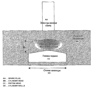
Exemplary embodiment of use of the invention in car internal combustion
engines is
illustrated in fig. 11. Discharge is created in the gap between cylinder head
and piston
initiating ignition throughout the entire volume at low concentration of fuel
in mixture which
results in reduction of burning time, decrease in fuel consumption and
reduction of pollutant
emissions.
Exemplary embodiment of use of pulse discharges for initiation of combustible
mixture combustion-reforming in plasma reformer is illustrated in fig. 12.
Discharge is
created in the coaxial gap between internal high-voltage electrode and outer
reformer wall
initiating plasma catalysis throughout the entire volume at high concentration
of fuel in
mixture which results in low-temperature reforming of hydrocarbon fuel into
hydrogen,
CA 02633758 2008-05-02
reduction of energy consumption per unit of hydrogen evolved and decrease in
amount of
hydrocarbons at the reformer outlet.
Exemplary embodiment of use of the claimed method for initiation of detonation
in
detonation engines and combustion chambers is illustrated in fig. 13. Fig. 13A
shows general
5 view of the large cross-section detonation combustion chamber in which
separate discharge
sections are mounted (fig. 13B). Discharge is created in the space with
barrier (insulator
partially covering the low-voltage electrode, fig. 13B). Such geometry allows
to maintain a
~ high value of electric field in the discharge region and to use relativelY
low voltages for
achieving uniformity of plasma formation
10 3=10"'~ > U/([dl-dz]/2 xn) > 3.10"'$
and relatively low values of rate of voltage increase across the gap
zf<3=10'gxL2xn/U
even at high initial gas pressures typical for detonation combustion chambers.
The unique
feature of this embodiment of discharge is that the value of the reduced field
in the discharge
15 gap is governed by the smallest distance between electrodes [dl-dz]/2, and
the time of filling
. the gap and reaching short-circuiting conditions by discharge is governed by
the distance
between the high-voltage electrode and that part of the low-voltage electrode
which is not
covered by dielectric layer (fig.13B).
CA 02633758 2008-05-02
-
21
LIST QF REFERENCES
l. T.Tachibana 11 Proc. 26th (Int.) Sympos. on Combust. Napoli,1996. WIP
Abstracts.
P. 385.
2. M.Lavid, D.Zhou, Y.-C.Li 11 Proc. 26th (Int.) Sympos. on Combust.
Napoli,1996.
WIP Abstracts. P. 410.
3. H.Furutani, F.Liu, J.Hama, S.Takahashi 11 Proc. 26th (Int.) Sympos. on
Combustion.
Napoli,1996. WIP Abstracts. P. 394.
. 4. G.Pilch, A.Britan, Bon-Dor Gabi, E.Sher Il Proc. 27th (Int.) Symp. on
Combust.
Boulder,1998. WIP-Abstracts. P. 95.
5. N.N.Semenov, Nobel Lecture, December 11,1956.
6. I.A.Semiokhin, B.V.Strakhov, A.I.4sipov. Kinetics of Chemical Reactions.
M.,
MSU Publishing House,1995.
7. A.P.Purmal. Simple Kinetics of Complex Reactions. M.: MPTI Publishing
House,
1998.
8. E.T.Denisov. Kinetics of Homogeneous Chemical Reactions. M.: Higher School
Publishing House,1988.
~
9. E. C. Samano, W. E. Carr, M. Seidl, and Brian S. Lee. An arc discharge
hydrogen
atom source,llReview of Scientific Instruments 64 (lo) (1993) 27462752.
10. D.A. Eichenberger and W.L. Roberts, Combust. Flame 118 (1999) 469.
11. L.S.Polak, A.A.Ovsyannikov, D.I.Solovetskiy, F.B.Vurzel. Theoretial and
Applied
Plasma Chemistry. M.: Nauka Publishing House ,1975.
12. L.M.Vasiliak, S.V.Kostuchenko, N.N.Kudriavtsev, I.V.Filugin. High-Speed
Ionization Waves at Electric Breakdown.ll Uspekhi Fizicheskikh Nauk Publishing
House,
Vo1.164 (No. 3),1994, p.161285.
CA 02633758 2008-05-02
+ 22
13. Zatsepin, Starikovskaya, Starikovskiy. Development of a Spatially Uniform
High-
Speed Ionization Wave in a Large Discharge Volume. llPlasma Physics Reports,
1998, Vol.
24, No. 7, p. 1--7.
14. S.M.Starikovskaya. Pulse Discharge at High Overvoltages: Peculiarities of
Development and Excitation of Gas Internal Degrees of Freedom. Doctoral
Thesis, 2000, p.
1221.
15. A.A.Radtsig, B.M.Smirnov. Handbook on Atomic and Molecular Physics. M.:
Atomizdat Publishing House,1980.
16. A.P.Zuev, A.Yu.Starikovskiy. Absorption Cross-Sections of the Molecules
02,
lo NG, N24, C02, H24, N02 in the UV Region of Spectra. ll Journal of Applied
Spectroscopy,
1990, March(3), Vol. 52, p. 455466.
17. Ya.B.Zeldovich, Yu.P.Raizer. Physics of Shock Waves and High-Temperature
Hydrodynamic Phenomena. Second Enlarged Edition. M.: Nauka Publishing
House,1966.
18. Statistical Physics, part I, Landau L.D., Lifshits E.M., Moscow 1976.
19. Thermodynamic Properties of Individual Substances, edited by Glushko V.P.,
S Nauka Publishing House, Moscow 1978.
20. J.Craggs, R.Meek. High Voltage Laboratory Technique. Butterworth
Scientific
Publi shers, London,1954.
21. S.A.Bozhenkov. Study of high-speed ionization wave influence on ignition
of
hydrogen-air and methane-air mixtures. B.Sc. thesis, 2002.
22. S.A.Bozhenkov, S.M.Starikovskaia and A.Yq.Starikovskii. Nanosecond gas
discharge ignition of H2 and CH4 containing mixtures. llCombustion and Flame
133 (2003)
133146.
23. G. P. Smith, D. M. Golden, M. Frenklach et al.,
http:llwww.me.berkeley.edulgri_mechl
CA 02633758 2008-05-02
23
24. C.D., Carter, S., Williams, L.C., Lee, S., Sidhu, J., Graham. AIAA Paper
2003-
0703. 41 st Aerospace meeting and Exibit. 6-9 Jan, Reno, Nevada, USA.
25. E.I., Mintoussov, S.V., Pancheshnyi, A.Yu., Starikovskii. AIAA paper 2004-
1013.
42nd Aerospace meeting and Exibit. 5-$ Jan 2004, Reno, Nevada, USA
26. J.W., Parish, B.N., Ganguly. AIAA paper. 42nd Aerospace meeting and
Exibit. 5-$
Jan 2004, Reno, Nevada, USA.
27. E.N. Kukaev. Investigation of Ignition of Combustible Mixtures by a
Nanosecond
S Gas Discharge and Flash PhotolYsis. M.Sc. thesis, 2004.
2$. H. Dkabe. Photochemistry of Small Molecules. M.: Mir Publishing
House,1981.
29. S.M., Starikovskaia, E.N., Kukaev, A.Yu., Kuksin, M.M., Nudnova, A.Yu.,
Starikovskii. Analysis of the spatial uniformity of the combustion of a
gaseous mixture
initiated by a nanosecond discharge.llCombustion and Flame.193 (2004) 177187
30. N., Lamoureux, C.-E., Paillard, V., Vaslier. Low hidrocarbon mixtures
ignition
delay times investigation behind reflected shock waves.llShock waves, (2002) 1
1 : 309322
31. E.V. Stupochenko, S.A. Losev, A.I. Osipov. Relaxation Processes in Shock
S Waves. M.: Nauka Pulishing House,1965.