Note: Descriptions are shown in the official language in which they were submitted.
CA 02633927 2008-06-11
WO 2007/082642 PCT(EP20071400045
Method for Operatinga Wind Energy Installation and a Wind Energy installation
Description
The invention relates to a method for operating a wind energy installation,
the
wind energy installation comprising a rotor, at least one rotor blade with an
adjustable
angle, a mechanical brake device for braking the rotor and an operational
control device
as well as a safety system. The invention further relates to a wind energy
installation
comprising a rotor, at least one rotor blade with an adjustable angle, a
mechanical brake
for bralang the rotor, an operational control device and a safety system.
According to
the invention a wind energy installation also is a wind power plant.
Methods for operating a wind energy installation and wind energy installations
are known per se. To this end, reference is made for example to the textbook,
"Windlu'aft Systemauslegung, Netzintegration und Regelung", Siegfried Heier,
4th
Edition, B.G. Teubner, February 2005. The operation of wind energy
installations and
wind energy installatians themselves are critical with regard to the design
thereof, in
particular with regard to safety aspects. In particular in strong winds
associated with
grid failure, in which the aerodynamic torque produced by the wind in the
rotor
encounters no resistance through the generator, it may lead to extreme tower
loads, in
particular tower foot bending moments, uncontrolled blade angle adjustments or
pitching and possibly even the triggering of a safety chain. As a result of
grid failure
andJor more generally as a result of load shedding by the generator, the rotor
starts to
accelerate in strong wind until the braking system of the wind energy
installation starts
to brake the rotor. Depending on the strength of the braking power, loads of
different
intensity are produced on the wind energy installation.
It is the object of the present invention to provide a reliable method for
operating
a wind energy installation and a correspondingly safe wind energy installation
with
reduced extreme loads.
This object is achieved by a method for operating a wind energy installation,
the
wind energy installation comprising a rotor, at least one rotor blade with an
adjustable
angle, a mechanical brake device for bralcing the rotor and an operational
control device
as well as a safety system, comprising the following method steps:
CA 02633927 2008-06-11
WO 2009/082642 2 PCT/EP2007/000045
- braking of the rotor by means of an angular adjustment at an average angular
adjustment rate of less than 8.5 /s of the at least one rotor blade after a
fault signal
occurs,
- braking of the rotor by means of the mechanical brake device as soon as the
rotational
speed of the rotor exceeds a predefinable first rotational speed limit, and
- triggering of the safety system as soon as the rotational speed of the rotor
exceeds a
predefmable second rotational speed limit, the rotor being braked and the
second
rotational speed limit being higher than the first rotational speed limit, the
second
rot,ational speed limit not being exceeded when the wind energy installation
is
operationally capable, even in the event of load shedding by the generator
combined
with an extreme gust of wind, the probability of occurrence thereof being less
than once
in three months. According to the invention an angular adjustment also means
pitching
throughout the description and the claims. Accordingly an angular adjustment
rate is
also a pitch rate.
As a result of the method according to the invention, it is possible even in
the
event of extreme gusts of wind and with simultaneous load shedding by the
generator,
to operate the wind energy installation such that loads which are too high are
not
produced, for example by a tower foot bending moment or a rotor bending
moment.
In particular, the combination of the braking of the rotor by means of an
angular
adjustment at an average angular adjustment rate of less than 8.5 /s and the
braking of
the rotor by means of the mechanical brake device, as soon as the rotational
speed of the
rotor exceeds a predefinable first rotational speed limit, combined with the
further
features, leads to the result according to the invention. The low angular
adjustment rate
serves, in particular, for preventing the rotor blades from being rotated too
rapidly, so
that an undesired reverse thrust is prevented. The underlying recognition of
the
invention is that an angular adjustment rate which is as slow as possible for
braking the
rotor reduces the loads. The drawback with the risk of the overspeed of the
rotor in the
event of unpredictable gusts of wind may be reliably controlled by the
additional
measures according to the invention (first and second rotational speed
limits). In the
prior art, such low angular adjustment rates in the event of malfunction, such
as for
example drop in load, have hitherto been disregarded, as the overspeed
conditions
occurring during gusts have led to unacceptably high loads.
CA 02633927 2008-06-11
WO 2007/082642 3 PCT/EP2007/000045
Within the scope of the invention, an averaged angular adjustment rate, in
particular, means an averaging of the angular adjustment rate over the time
period in
which the braking takes place via an angular adjustment, in particular as long
as the
mechanical brake device does not brake the rotor. Preferably the angal,ar
adjustment rate
for braking the rotor by means of an angular adjustment is not only on average
less than
8.5 /s, but permanently below 8.50/s.
Preferably, the mechanical brake device in a wind energy installation acts by
means of gears on the rapidly rotating side of the drive train. On this side
is also located
the generator with its rotating part denoted as the rotor. The mechanical
brake device
may, however, also be arranged on the low speed side of the drive train, i.e.
on the side
between the gears and the rotor blades. The wind energy installation may,
however, also
be designed to be gearless, so that the brake acts in the region of the rotor
hub or the
generator rotor. Within the scope of the invention, the term "rotor" also
encompasses
the telTns "drive train", "high speed shaft", "generator rotor", "gears",
"rotor shaft (= low
speed shaft), "rotor hub" and "rotor blades". A braking of the rotor means, in
particular,
the braking of the drive train.
The braking of the rotor by means of an angular adjustment may take place
additionally, or as an alternative, to braking the rotor by means of the
mechanical brake
device. Initially an alternative braking of the rotor may also take place via
an angular
adjustment and subsequently both braking variants may be carried out, namely
by
means of the angular adjustment and by means of the mechanical brake device.
After triggering the safety system, the rotor may, in particular preferably,
be
braked by overriding the operational control device. The operational control
device
may, however, also be part of the safety system, and/or the safety system may
be part of
the operational control device, so that the operational control device does
not
necessarily have to be overridden for braking after triggering the safety
system.
The form and strength of a gust of wind may be calculated by a normal wind
profile model, as for example is indicated in the textbook, "Wind Energy
Handbook",
Tony Burton, David Sharpe, Nick Jenkins, Ervin Bossanyi, John Wiley and Sons
Ltd,
November 2002, on pages 214 to 218. In particular the formula (5.1) is of
relevance
here, for the case according to the invention of the probability of occurrence
of less than
once in three months a factor 0 of approximately 4.6 being able to be set. For
the sake
CA 02633927 2008-06-11
WO 207ro82642 4 FcrlEPZOO7/OOOQaS
of simplicity, 10 s is set as the time period of the extreme gust of wind
(described in this
document as "gust"). For the design of a wind energy installation and the
level of the
first and second rotational speed limits, according to the location of the
wind energy
installation, predefined and/or predefinable load cases are assumed which have
to be
able to be supported during operation of the wind energy installation andJor
by the wind
energy installation without damage thereto. For example, Germanischer Lloyd
and/or
other corresponding safety institutes defii.ne such load cases. According to
the defniition
of the load cases, corresponding computer programs which, for example,
correspond to
the "Flex" computer program from Stig Oye and/or have been derived andlor
developed
therefrom, are used to simulate wind energy installations and the operation of
wind
energy installations and to establish, depending on the load case, which loads
may occur
on the wind energy installation during operation. These loads will generally
occur with
predetermined probabilities. For example, in the document "Wind Energy
Handbook"
by Tony Burton et al. which has been mentioned above, in the "load case 1.5"
on page
216 to page 218 an annual gust, i.e. an extremely strong gust which occurs
with a
probability of once a year, is assumed.
The object is further achieved by a method for operating a wind energy
installation, the wind energy installation comprising a rotor, at least one
rotor blade with
an adjustable angle, a mechanical brake device for braking the rotor, an
operational
control device and a safety systemõ comprising the following method steps:
- braking of the rotor by means of an angular adjustment at an average angular
adjustment rate of less than 8.5 !s of the at least one rotor blade after a
fault signal
occurs,
- braldng of the rotor by means of the mechanical brake device as soon as the
rotational
speed of the rotor exceeds a predefinable first rotational speed limit, and
the mechanical
braking is triggered by the operational control device,
- triggering of the safety system, as soon as the rotational speed of the
rotor exceeds a
predefinable second rotational speed limit, the rotor being braked and the
second
rotational speed limit being higher than the first rotational speed limit.
Preferably, the second rotational speed limit in the event of a wind gust with
a
probability of occurrence of once a year is not exceeded. For example,
Germanischer
Lloyd indicates that in the event of a predetermined load case, such as for
example the
CA 02633927 2008-06-11
WO 2007/082642 5 PCT/EP2007/000045
occurrence of an "annual gust", i.e. an extreme gust of wind which occurs with
a
probability of occurrence of once a year, and namely at the corresponding
location of
the wind energy installation, certain loads in the rotor, for example, may not
be
exceeded and/or the occurring loads have to have a defined safety level in
comparison
with and/or with regard to the maximum occurring loads.
Setting the second rotational speed limit so that it is not exceeded in the
event of
an annual gust, has the advantage relative to the setting for a three monthly
gust, that the
brake is considerably less frequently applied and the wear of the brake and
the entire
drive train is therefore reduced.
Preferably the fault signal includes exceeding a third rotational speed limit
which is lower than the first rotational speed limit, load shedding by the
generator, an
error in the grid and/or an error in the angular adjusiment of at least one
rotor blade.
An even more reliable operation is possible if the angular adjustment rate of
the
at least one rotor blade after the occurrence of the fault signal is less than
8 /s, in
particular preferably less than 6.5 /s and in particular preferably less than
4.6 /s, in
particular less than 4.5 /s. These values may be regarded as average values
and/or as
actual values without averaging. The angular adjustment rate is expediently
controlled
by a control device associated with the operational control device or a
separate control
device. In this case, the operational control device predetermines the angular
adjustment
rate and the control device thus controls the angular adjustment rate and/or
the
adjustment of the angle of the respective rotor blade.
Preferably, the angutar adjustment rate of the at least one rotor blade when
exceeding a predefinable blade angle is altered to a low angular adjustment
rate, in
particular to an angular adjustment rate which is less than half, in
particular less than a
quarter of the previous angular adjustment rate.
When the fault signal occurs, based on the existing blade angle position of
the
rotor blade, the blade angle is rotated at the angular adjustment rate
according to the
invention in the direction of the feathering position. In this case, the
initial point may be
a zero position of the rotor blade. However, a position may also be present
which
already is advanced in the direction of the feathering position. The zero
position is
preferably the rotor blade position at which during operation at optimal speed
the
maximum power may be achieved, frequently also denoted as the operating
position.
CA 02633927 2008-06-11
WO 20071082642 6 PCT/EP2007I000045
The feathering position is preferably the position in which no power may be
produced.
The rotor blades are in this case, in the manner of a vane, rotated out of the
wind.
Preferably, the first rotational speed limit is in a range of more than 15%
above a
rated speed of the wind energy installation, which in particular has a rated
power of
more than 1.45 MW. The rated speed is, within the scope of the invention, a
rotational
speed at which the wind energy installation first achieves a rated power. The
corresponding wind speed is thus known as rated wind speed. In particular with
wind
energy installations in which at high wind speeds above the rated wind speed
the
operating speed is reduced, the term "rated speed" may also refer to the
reduced
operating speed at the respective operating point. A rated speed, for example
in a wind
energy installation with a rated power of 1.5 MW, may be 1,800 revolutions per
minute
(rpm). This rated speed is measured on the rotor of the generator or on the
high speed
shaft of the gear box. A further rated speed may, however, also be defined,
namely that
which prevails on the rotor hub andlor which prevails in the generator, when
no gear
box is present. These corresponding rated speeds may preferably be in the
range of 5 to
20 revolutions per minute, in particular preferably at 8 to 18 revolutions per
minute. By
rated power, is understood the maximum continuous power of the wind energy
installation, i.e. the power at which there is approximately an optimum amouat
of power
obtained, with simultaneously the lowest possible wear on the wind energy
installation.
The rated power is, in particular with offshore wind energy installations, in
particular at
high wind locations, the power at which the wind energy installation generates
the
greatest total power over the entire service life.
Preferably, the first rotational speed limit is between 20 and 35%, in
particular
between 22 and 28% above the rated speed of the wind energy installation.
Particularly
preferred is a value approximately 25% above the rated speed of the wind
energy
installation.
The second rotational speed limit is preferably in a range of 35% to 45% above
a
rated speed of the wind energy installation which, in particular, has a rated
power of
more than 1.45 MW. This second rotational speed limit, at the exceeding of
which the
safety system is triggered, is above the rotationat speed limit which was
hitherto usual
for installations greater than 1.45 MW in the prior art. With smaller and thus
less
CA 02633927 2008-06-11
WO 20071aS1642 7 PC'17EP20071000045
sluggish and load-critical installations (for example 600 kW) this rotational
speed limit
may be set higher.
Preferably, the second rotational speed limit is in a range of 5% to 20% above
the first rotational speed limit of the wind energy installation, the low
range in particular
being advantageous with very rigid, for example gearless drive trains, as no
torsional
vibrations occur there.
Particularly preferably, the third rotational speed limit is in the range of
10 to
20%, in particular from 15 to 17% above a rated speed of a wind energy
installation,
which in particular has a rated power of more than 1.45 MW. The third
rotational speed
limit is relatively low. This means that braking the wind energy installation
via the
aerodynamic brake by adjusting the angle of the at least one rotor blade by a
relatively
low angular adjustment rate already begins at a relatively low rotational
speed limit.
Preferably, the braking of the rotor by means of the mechanical brake device
is
terminated when a fourth predefinable rotational speed limit is fallen below.
This
preferably occurs when the wind energy installation is in a safe installation
state, the
extreme load case being therefore at an end.
When the braking of the rotor by means of the mechanical brake device is
terminated, when an average rotor blade angle exceeds a predefinable threshold
value
and a predefinable time since the start of the braking of the rotor by means
of the
mechanical brake device (19) is exceeded, a protective and safe operation in
particular
of the mechanical brake device is possible. In particular, therefore,
dangerous
overheating of the brake is avoided.
The object is fizrther achieved by a method for operating a wind energy
installation, the wind energy installation comprising a rotor, at least one
rotor blade with
an adjustable angle, a tower, an operational control device and a safety
system,
comprising the following method steps:
- operation of the wind energy installation regulated or controlled by the
operational
control device for generating electrical voltage until a fault signal occurs,
- triggering of the safety system when the fault signal occurs and subsequent
braking of
the rotor via an angular adjustment at an, in particular initial, average
angular
adjustment rate of less than 6.5 /s of the at least one rotor blade, detected
over a time
period of a half, up to a whole, vibration period of the tower.
CA 02633927 2008-06-11
WO 2007/082642 $ PCT/6P2007/000045
Preferably, the average angular adjustrnent rate is less than 6 /s, in
particular less
than 5 /s, in particular less than 4.6 /s, in particular less than 4.5 /s.
Preferably, the angular adjustment rate is controlled or regulated and is
further
reduced with increasing enlargement of the blade angle and/or a reduction of
the
rotational speed.
Preferably, the fault signal in the event of load shedding by a generator is
coupled to an extreme gust of wind, the probability of occurrence of the gust
of wind
being less than once in three months, in particular less than once a year.
The object is fuither achieved by a wind energy installation comprising a
rotor,
at least one rotor blade with an adjustable angle, a mechanical brake for
braking the
rotor, an operational control device and a safety system, a first brake device
being
provided which brakes the rotor via an angular adjustment of the at least one
rotor blade
at an average angular adjustment rate of less than 8.5% in the presence of a
fault signal,
a second brake device being provided for the mechanical braking of the rotor,
as soon as
the rotational speed of the rotor exceeds a predefinable first rotational
speed limit, the
safety system in the case in which the rotational speed of the rotor exceeds a
predefinable second rotational speed limit, being provided for braking the
rotor, the
second rotational speed limit being higher than the first rotational speed
limit, the
second rotational speed limit and the wind energy installation being
dimensioned such
that when the wind energy installation is operationally capable, even in the
event of load
shedding by the generator combined with an extreme gust of wind, the
probability of
occurrence thereof being less than once in three months, the second rotational
speed
limit is not exceeded.
Within the scope of the invention, "the presence of a fanIt signal" in
particular
also means "in the event of the occurrence of a fault signal".
The object is further achieved by a wind energy installation comprising a
rotor,
at least one rotor blade with an adjustable angle, a mechanical brake for
bralcing the
rotor, an operational control device and a safety system, a first brake device
being
provided which brakes the rotor by means of an angular adjustment of the at
least one
rotor blade at an average angular adjustment rate of less than 8.5% in the
presence of a
fault signal, a second brake device being provided for the mechanical braking
of the
rotor, as soon as the rotational speed of the rotor exceeds a predefinable
first rotational
CA 02633927 2008-06-11
WO 2007l082642 9 PCT/EP20071000045
speed limit, the second brake device being able to be triggered by the
operational
control device, the safety system in the case in which the rotational speed of
the rotor
exceeds a predefinable second rotational speed limit, being provided for
braking the
rotor, the second rotational speed limit being higher than the first
rotational speed limit.
Preferably, the second rotational speed limit in the event of a gust of wind
with a
probability of occurrence of once a year is not exceeded. This means, in
particular, that
the probability of occurrence of such a load is so small that it may be
detected at a
relatively low level of safety.
Preferably, the fault signal includes exceeding a third rotational speed limit
which is lower than the first rotational speed limit, load shedding by the
generator, an
error in the grid and/or an error in the angular adjustment of at least one
rotor blade.
Preferably, the angular adjustment rate of the at least one rotor blade in the
presence of
the fault signal is less than 8 /s, in particular less than 6.5 /s, in
particular less tha.n
4.6 /s, in particular less than 4.5 /s. The angular adjustment rate is
preferably able to be
controlled by a control device associated with the operational control device
or a
separate control device. The angular adjustment rate of the at least one rotor
blade is
expediently able to be altered, when exceeding a predefinable blade angle, to
a lower
angular adjustment rate, in particular to an angular adjustment rate which is
less than
half, in particular less than a quarter of the previous angular adjustment
rate.
Alternatively to the control by the control device, the reduction of the
adjustment rate
may also take place by a suitable hardware arrangement, for example staged
battery
packs for supplying energy to the actuating drives.
The first rotational speed Iimit is preferably in a range of more than 15%
above a
rated speed of the wind energy installation, which in particular has a rated
power of
more than 1.45 MW. At a rated speed of 1,800 revolutions per minute, the first
rotational speed limit is then preferably in a range of more than 2,070
revolutions per
minute and in particular preferably in a range of more than 2,160 revolutions
per
minute. Preferably, the first rotational speed limit is between 20 and 35%, in
particular
between 22 and 28% above the rated speed of the wind energy installation. This
corresponds with a rated speed of 1,800 to a range between 2,160 and 2,430, in
particular a range of 2,196 to 2,304 revolutions per minute.
CA 02633927 2008-06-11
WO 2007/082642 10 PCT~200710OM5
Preferably, the second rotational speed limit is in a range of 35% to 45%
above a
rated speed of the wind energy installation which, in particular, has a rated
power of
more than 1.45 MW. At a rated speed of 1,800 revolutions per minute this
corresponds
to a range of 2,430 revolutions per minute to 2,610 revolutions per minute.
Preferably, the second rotational speed limit is in a range of 5% to 20% above
the first rotational speed limit of the wind energy installation. This is at a
first rotational
speed limit of 2,200 revolutions per minute, from 2,310 to 2,640 revolutions
per minute.
Prefcrably, the third rotational speed limit is in a range of 10% to 20%, in
particular of 15% to 17%, above a rated speed of the wind energy installation
which, in
particular, has a rated power of more than 1.45 MW. This is at a rated speed
of 1,800
revolutions per minute, in a range of 1,980 to 2,160 revolutions per minute,
in particular
in a range of 2,070 to 2,106 revolutions per minute. Preferably, the braking
of the rotor
by means of the mechanical brake device may be terminated when falling below a
fourth predefinable rotational speed limit, for example at a rated speed.
Moreover,
preferably the bralcing of the rotor by means of the mechanical brake device
may be
ternainated, when an average rotor blade angle exceeds a predefinable
threshold value
and a predefinable time since the start of the braking of the rotor by means
of the
mechanical brake device is exceeded.
The object is further achieved by a wind energy installation comprising a
rotor,
at least one rotor blade with an adjustable angle, a tower, in particular
preferably a
mechanical brake for braking the rotor, an operational control device and a
safety
system, the operational control device being provided for the regulated or
controlled
operation of the wind energy installation for generating electrical voltage
until a fault
signal occurs, the safety system being able to be triggered with andlor after
the
occurrence of the fault signal and by means of the safety system a braki.ng of
the rotor
being produced by means of an angular adjustment at an, in particular initial,
average
angular adjustment rate of less than 6.5 /s of the at least one rotor blade
detected over a
time period of a half to a whole vibration period of the tower.
The recognition underlying the invention is that excessive excitation of tower
vibration by negative rotor thrust may be counteracted, when at least for a
duration of a
half vibration period of the tower, advantageously however for the duration of
a whole
vibration period, the initial angular adjustment rate is restricted after the
fault signal to
CA 02633927 2008-06-11
WO 2007/082642 11 PCT/EP2007/000045
low values below 6.5 /s. Conventional natural frequencies of the tower are
currently
between 0.2 - 0.4 Hz, i.e. a vibration period is between 2.5 and 5 seconds.
Thus with a
stiff tower the adjn.stment rate may be restricted to the aforementioned value
for at least
1.3 seconds after triggering the fauit signal, and with a soft tower for 2.5
seconds to the
aforementioned value. lt is substantially more efficient, however, to carry
out the
restriction for approximately 2.5 and/or 5 seconds, in order to avoid as far
as possible an
activation of the first stress cycle of the tower a$er the fault signal. With
larger
installations in the future, with lower natural frequencies to be expected,
the ratios are
naturally able to be accordingly adapted.
Preferably the average angular adjustment rate is less than 6 /s, in
particular less
than 5 /s, in particular less than 4.5 /s.
Preferably the angular adjustment rate may be controlled or regulated and may
be fiuther reduced with increasing enlargement of the blade angle and/or
reduction of
the rotational speed.
Preferably, the fault signal in the event of load shedding by a generator is
coupled to an extreme gust of wind, the probability of occurrence of the gust
of wind
being less than once in three months, in particular less than once a year.
The object is fiuther achieved by a method for operating a wind energy
installation, the wind energy installation comprising a rotor, at least one
rotor blade with
an adjustable angle, a mechanical brake device for braking the rotor, an
operational
control device and a safety system, comprising the following method steps:
- braking of the rotor by means of an angular adjustment at an average angular
adjustment rate of less than 6.5 /s of the at least one rotor blade after a
fault signal
occurs,
- braking of the rotor by means of the mechanical brake device as soon as the
rotational
speed of the rotor exceeds a predefinable first rotational speed limit, and
- triggering of the safety system, as soon as the rotational speed of the
rotor exceeds a
predefinable second rotational speed limit, the second rotational speed limit
being
higher than the first rotational speed limit and the first rotational speed
limit being in a
range of more than 15% above a rated speed of the wind energy installation,
which in
particular has a rated power of more than 1.45 MW.
CA 02633927 2008-06-11
WO 2007/082642 12 PCT/EP20071000045
Preferably, the first rotational speed limit is between 20 and 35%, in
particular
between 22 and 28%, above the rated speed of the wind energy installation.
Moreover,
preferably the second rotational speed limit is in a range of 35% to 45% above
a rated
speed of the wind energy installation, which in particular has a rated power
of more than
1.45 MW. Preferably, the fault signal has a third rotational speed limit which
is in a
range of 10% to 20%, in particular 15% to 17%, above a rated speed of the wind
energy
installation.
Accordingly, the object is achieved by a wind energy installation which
comprises a rotor, at least one rotor blade with an adjustable angle, a
mechanical brake
for braking the rotor, an operational control device and a safety device, a
first brake
device being provided which brakes the rotor by means of an angular adjustment
of the
at least one rotor blade at an average angular adjustment rate of less than
6.5 /s in the
presence of a fault signal, a second brake device being provided for the
mechanical
braking of the rotor, as soon as the rotational speed of the rotor exceeds a
predefinable
fust rotational speed limit, the safety system in the case in which the
rotational speed of
the rotor exceeds a predefinable second rotational speed limit, being provided
for
braking the rotor, the second rotational speed limit being higher than the
first rotational
speed limit, the first rotational speed limit being in a range of more than
15% above a
rated speed of the wind energy installation, which in particular has a rated
power of
more than 1.45 MW. The further preferred features of the wind energy
installation
according to the invention result from that which has been disclosed above.
The invention is disclosed hereinafter, without restricting the general
inventive
idea, with reference to embodiments by referring to the drawings, with regard
to all
details according to the invention not described in more detail reference is
expressly
made to the drawings, in which:
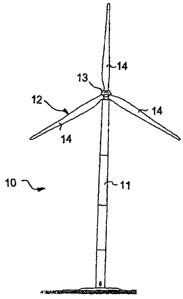
Figure 1 shows a schematic view of a wind energy installation,
Figure 2 shows a schematic block diagram of essential components of a
wind energy installation,
CA 02633927 2008-06-11
WO 20071082642 13 PGTlEP200710UO045
Figure 3 shows schematic diagrams for two different load cases, which
occur in a wind energy installation according to the invention,
namely
Figure 3a shows the wind speed over the time of a calculated annual gust,
Figure 3b shows the angular adjustment rate over the time,
Figure 3c shows the rotational speed over the time,
Figure 3d shows the electrical power over the time,
Figure 3e shows the braking moment over the time,
Figure 3f shows a tower foot bending moment over the time and
Figure 3g shows the rotor torque over the time,
Figure 4 shows schematic diagrams of values of two wind energy
installations, which are on the one hand (solid lines) according to
the invention and on the other hand (dotted lines) according to the
prior art,
Figure 4a shows the wind speed of a calculated gust over the time,
Figure 4b shows an angular adjustment rate over the time,
Figure 4c shows a rotational speed over the time,
Figure 4d shows an electrical power over the time,
Figure 4e shows a braking moment over the time,
CA 02633927 2008-06-11
WO 2007/082642 14' PCT/EP2007/000045
Figure 4f shows a tower foot bending moment over the time and
Figure 4g shows a rotor torque over the time.
In the following figures, the same or similar elements and/or corresponding
parts
are respectively provided with the same reference numerals, so that a
corresponding
fiuther representation may be dispensed with.
Figure 1 shows a schematic representation of a wind energy installation 10.
The
wind energy installation 10 comprises a tower 11 and a rotor 12 which
comprises three
rotor blades 14 which are attached to a rotor hub 13. In the event of wind,
the rotor 12
rotates in a manner known per se. As a result, power from a generator
connected to the
rotor 12 and/or to the rotor hub 13 may be generated and discharged to a
consumer
network.
Figure 2 schematically shows essential components of the wind energy
installation 10 according to the invention. An operational control 15 which
also may be
denoted as an operational control device or operational control system,
controls and/or
regulates the operation of the wind energy installation 10. Adjacent to the
operational
control 15 is a safety monitoring device 16 which is connected to a safety
chain 20. The
safety chain 20 comprises, for example, a vibration detector, a manual
(emergency)
switch and a rotational speed relay. The safety chain 20 is used in the
presence of an
event relevant to safety, for example vibrations which are too great or the
actuation of
the emergency switch by an operating person, so that the wind energy
installation is
decelerated into an uncritical state. The safety chain 20 may be designed as a
hardware
chain. When the safety chain 20 is triggered, which is indicated by the arrow
to the
electrical components 21, the generator 23 is disconnected from the grid 25
and the
rotor shaft 9 andlor the high speed shaft 22 braked, for example via the blade
adjustment 18 and/or the mechanical brake 19 or even, which is not shown,
directly by
overriding one or more regulating or control devices such as the blade
adjustment 19.
The safety monitoring device 16 may also be designed such that said safety
monitoring
device monitors the operational control 15 for functionality. The safety
monitoring
device 16 is preferably designed in this respect as a type of "watch dog". The
CA 02633927 2008-06-11
WO 20071082642 15 PCT/EP2007/000045
operational contro115', as shown in dotted lines, may also comprise the safety
monitoring device 16. The operational control 15' therefore has integrated
safety
monitoring 16.
The operational control 15, 15' is connected via corresponding electronic data
lines to a controller 17 and the blade adjustment 18, and moreover to the
mechanical
brake 19. By the term "blade adj ustment" 18 is understood, in particular, an
actuator
which ensures a blade adjustment of the rotor blades 14. Accordingly, by the
term
"mechanical brake" 19 is understood an actuator which ensures that the
mechanical
brake 19 acts in this embodiment on the high speed shaft 22. The mechanical
brake 19
may also act on the rotor shaft 9 which is, however, not shown.
A data connection is denoted at 26 which supplies a rotor blade angle and/or
the
rotor blade angle of the rotor blades 14 to the operational control 15 and/or
15'. A data
connection is shown by the reference numeral 27 which supplies an actual
rotational
speed of the high speed shaft 22 to the operational control 15 and/or 15'. A
data line is
denoted at 30 which supplies a fault signal, which in this embodiment is based
on
electrical components 21, to the operational control 15 and/or 15'.
The operation of the wind energy installation is as follows. In the event of
wind,
the rotor 12 is rotated according to the rotational direction 29. As a result,
the rotor shaft
9 also rotates which rotates the high speed shaft 22 by means of a gear box 24
in a ratio
of, for example, 1:100. As a result, in the generator 23 an electrical voltage
is generated
which is controlled, converted an.d/or changed into alternating current in the
electrical
components 21. At the output of the electrical components 21 a connection to
the grid
25 is provided by which the consumer is supplied with voltage andlor
electricad power.
Generally known designs for regulating and controlling wind energy
installations are,
for example, disclosed in chapter 5 of the textbook, ""Windkraft
Systemauslegung,
Netzintegration und Regelung" by Siegfried Heier, which is cited above.
In the event of an extreme gust of wind 31 it may arise in combination with
load
shedding by the generator, i.e. in particular an abrupt loss of the grid load,
for example
by a failure of a converter, a generator, a transformer, a grid failure or the
triggering of a
safety chain, such that the rotational speed of the rotor and/or the generator
reaches very
critical and high rotational speeds, so that sudden braking is necessary which
may lead
to considerable fatigue of the material of the wind energy installation or to
damage.
CA 02633927 2008-06-11
WO 2007/082642 1 ~ PCT/EP2007/000045
The invention works counter thereto, because the rotor 12 andlor the rotor
shaft
9 and/or accordingly the high speed shaft 22 is braked over a relatively slow
angular
adjustment 28 even when a corresponding fault signal occurs, for example even
when a
relatively low third rotational speed limit is exceeded. As a result of the
relatively low
angular adjustment rate or pitch rate of less than 8.5 Is, in particular less
than 6.5 /s,
load-free braking is initiated.
If this braking due to the strength of the gust of wind 31 is not sufficient
and if
the rotational speed of the rotor which within the scope of the invention also
encompasses the t.erxns drive train and generator rotor, exceeds a
predefinable first
rotational speed limit which is higher than the third rotational speed limit,
the
mechanical brake 19 is initiated via the braking program according to the
invention by
means of the operational contro115 and/or 15'. Only when both braking
variants,
namely the aerodynamic braking by means of the blade adjustment 18 and the
mechanical braking by means of the mechanical brake 19 are not sufficient, and
the gust
of wind 31 is sufficiently strong that a second rotational speed limit is
exceeded, is the
safety system 16,20 triggered.
The safety system 16, 20 causes a triggering of the brake devices which are
not
required for the operational control and possibly an even stronger braking
effect, for
example a blade adjustment with a greater angular adjustment rate and/or an
application
of a hydraulic brake with greater hydraulic pressure. The second rotational
speed limit
is, however, set such that said rotational speed limit is achieved, even in
the event of
load shedding by the generator, only in the event of such extreme gusts of
wind which
occur with a probability of less than once in three months. In this particular
embodiment, a gust of wind which has a probability of occurrence of less than
once a
year, is assumed. A simple embodiment of a safety system which may be easily
used
which comprises a safety monitoring device 16 and a safety chain 20, is for
example
disclosed on pages 473 and 474 of the publication "Wind Energy Handbook" which
has
been mentioned above.
In Figures 3 a to 3 g, diagrams are shown by means of which the invention is
to
be explained for two different load cases. Figure 3a shows a diagram of the
wind speed
over the time, in this case a conventional extreme operating gust being shown,
which
for example may be calculated in the formula 5.1 on page 215 of the document
"Wind
CA 02633927 2008-06-11
WO 2007/082642 17 PCT/EP2007/000045
Energy Handbook" which is cited in more detail above. It refers to a gust
which at the
location considered occurs with a probability of precisely once a year. Figure
3d shows
a diagram of the electrical power in kW over the time, two cases being shown,
namely
the first case in which at approximately 7.5 seconds load shedding occurs,
namely at the
lowest point of the gust and in comparison thereto at approximately 9 seconds,
which
corresponds to a position which may be identified approximately in the centre
of the
rising flank of the gust from Figure 3a. The second case is the case which is
more
critical for the wind energy installation and shown in dotted lines. For the
safe design of
a wind energy installation, the load shedding has to be able to occur at any
time without
a dangerous situation arising.
Figure 3b shows the angular adjustment rate in /s of a rotor blade 14. It may
be
initially identified from Figure 3d that in both cases due to the form of the
gust at lower
wind speeds associated therewith, the pitch rate and/or angular adjustment
rate are
initially negative, i.e. the rotor blades are positioned into the wind, so
that a greater
torque may be generated. In the event of load shedding, in both cases the
angular
adjustment rate is set by the operational control relatively rapidly to a
range of 5 /s.
Smaller falls in the angular adjustment rate are based on a brief overload of
the angular
adjustment drives.
The rotational speed of the high speed shaft 22 generated by the gust is shown
in
Figure 3c. The undulation of the rotational speed signal is based on the
torsional
vibration of the drive train described below. In the first uncritical case,
the rotational
speed increases to almost 2,200 revolutions per minute and in the more
critical case
(dotted line) said rotational speed increases to slightly below 2,500
revolutions per
minute. For this embodiment, the second rotational speed limit is preferably
set to 2,500
revolutions per minute. By increasing the trigger speed for the safety chain
to 2,500
revolutions per minute, the triggering of the safety chain is avoided. Thus
the loads of
the wind energy installation may be markedly reduced. The conventional trigger
speed
for the safety chain in wind energy installations in the order of 1.5 MW and
higher is,
for example, at 2,400 revolutions per minute.
In Figure 3e the braking moment of the mechanical brake over the time is shown
schematically in a diagram. It may be seen that for the first case (solid
line) the
mechanical brake is not activated as the fust rotational speed limit is not
exceeded.
CA 02633927 2008-06-11
WO 20071082642 Z 8 PCT/EP2007/000045
Only for the second case (dotted line) is the mechanical brake activated when
exceeding
the first rotational speed limit of 2,260 revoiutions per minute and engages
at
approximately 11.5 seconds, and with a small time delay the mechanical brake
starts to
act.
In Figure 3 f the tower foot bending moment is shown in kNm over the time for
both cases. It may be seen clearly that the second case (dotted line) is more
critical with
regard to the tower foot bending moment. It may also be seen that in both
cases a
dampened vibration of the tower results from the gust.
In Figure 3g the rotor torque is shown in kNm. Similarly in this case the
different cases are shown in solid and dotted lines. It may be seen that the
drive train is
activated by the sudden load shedding in both cases to create a strong
torsional
vibration, which may be compared with a prestressed torsion spring which is
suddenly
released. In the second (case shown in dotted lines) the displacement of the
vibration by
the applied mechanical brake may be seen.
In order to clarify the invention even further, in Figures 4a to 4g a
corresponding
load case of a corresponding extreme gust of wind (annual gust) is shown
according to
Figure 4a in the event of load shedding by the generator according to Figure
4d. A
different embodiment of the method is shown, firstly a preferred operation of
the wind
energy installation according to the invention (solid lines) and secondly a
slightly less
preferred but inventive operational control. This has in contrast to the prior
art already
very low blade adjustment rates which have been set to very low values of 5 /s
and/or
6 /s in the event of an emergency stop.
T'his operational control, however, has no first rotational speed limit for
triggering the brake via the operational control, but merely the triggering of
the brake by
the safety device at a rotational speed of 2,400 revolutions per minute. This
operational
control sequence, shown in dotted lines, is initially described.
According to Figure 4d it may be seen that the load shedding takes place
approximately in the centre of the rising flank of the gust of wind of Figure
4a, i.e. in
the critical range. In the less preferred embodiment, in the event of load
shedding, a
blade adjustment rate of 5 /s is required. When exceeding the trigger speed of
2,400
revolutions per minute (see Figure 4c), an emergency stop is triggered by the
safety
device. A higher blade adjustment rate of 6 ls is required which, however, may
not be
CA 02633927 2008-06-11
WO 2007/082642 19 PCT/EP2007/000045
maintained constant due to an angular adju.stment device designed with a
narrow range.
At the same time, the mechanical brake is triggered so that during this
operating mode a
more rapid rotational speed reduction results than in the preferred embodiment
shown in
solid lines. Relatively high tower foot bending moments (Figure 4f) result
therefrom.
However, in the preferred embodiment according to the invention according to
the solid line in Figure 4b the blade adjustment rate is set and regulated to
less than
4.6 !s, in particular to precisely 4 ls. When exceeding the first rotational
speed limit (in
this case 2,270 revolutions per minute) the mechanical brake engages according
to
Figure 4e, i.e. slightly earlier than in the less preferred embodiment. As a
result of the
low blade adjustment speed, the rotor delay is less abrupt as a whole.
Accordingly,
according to Figure 4f more favourable tower foot bending moments result in
the
preferred embodiment (solid line) in comparison with the less preferred
embodiment
(dotted line). The rotor torque over the time is accordingly shown in Figure
4g. A
defined increase of the drive train load may be seen, which however is
acceptable in
comparison with the load reduction in the tower, in particular as it refers to
a very rare
load case. It may also be seen that negative braking moments arise as the
rotor vibrates
against the brake.
The invention relates therefore to the design and operation of wind energy
installations, in particular for DLC 1.5 (Design Load Case for an Annual
Operating Gust
with Grid Failure). In a conventional operational control, tower foot bending
moments
of up to 100,000 kNm (including safety factors) occur. An increased
aerodynamic thrust
which is greater the higher and more dynamic the tower is, i.e. the lower the
natural
frequency of the tower is, may additionally increase the natural dynamics of
the tower.
By altering the blade adjustment rate from, for example 6 to 5 ls and
increasing
the trigger speed for the safety chain from 2,400 to 2,500 revolutions per
minute and
providing a mechanical brake power when exceeding a first speed limit of 2,200
revolutions per minute, in the exemplary installation shown, at 21VIW rated
power, a
reduction in the tower foot bending moments of 14% may be easily achieved. The
first
rotational speed limit is preferably selected such that in the event of grid
failure and/or
loss of the grid load, without the occurrence of a gust, the blade adjustment
is sufficient
in order to ensure a safe operation without a mechanical brake. This only
occurs when
additionally a gust of wind occurs at an unfavourable time. Increasing the
first rotational
CA 02633927 2008-06-11
WO 2007/082642 20 PC'r1EP2007l000045
speed limit, for example to 2,230 or 2,270 revolutions per minute, results
only in a
slightly greater tower foot bending moment in comparison with the case at
2,200
revolutions per minute, which is why said tower foot bending moment, as shown
in
Figure 4, may be advantageous for simple parametering of the operational
control
system and/or the operational control device, for example when this rotational
speed
limit is already present for other operational control sequences. A further
reduction in
the tower foot bending moment may be achieved by the blade adjustment rate
being
further minimised, for example preferably to 4.5 /s or further preferably to
4/s as
shown in Figure 4b.
The second rotational speed limit may, in a 1.5 MW installation, be set higher
than usual by the invention, for example to 2,570 revolutions per minute or
even to
2,660 revolutions per minute. As a result of the invention, the mechanical
brake which
is shown in Figure 4e, is actuated earlier than was previously usual.
Moreover, a high
blade adjustment rate, for example by using an uncontrolled adjustment,
directly via a
battery, is avoided. The drive train load is in this case, as may be seen in
Figure 4g, not
markedly worsened. Preferably, the method for operating the wind energy
installation is
only used at average wind speeds of greater than 9m/s and less than
approximately 20
m/s.
The invention has been shown above in several variants combined with one
another and also in individual variants. The above disclosure may be
understood by the
person slcilled in the art such that even the individual variants may be
combined. In
particular, parts or a part of the subject-matter of an inventive solution
which has been
reflected in a subsequent subordinate claim, and/or one or more preferred
embodiments
may be features of a further inventive solution in which this feature or these
features are
not mentioned directly in the description in connection with this solution.
CA 02633927 2008-06-11
WO 2007/082642 21 PCT/EP2007/000045
List of reference numerals
Wind energy installation
11 Tower
12 Rotor
13 Rotor shaft
14 Rotor blade
Operational control
15' Operational control with integrated safety monitoring device
16 Safety monitoring device
17 Contraller
18 Blade adjustment
19 Mechanical brake
Safety chain
21 Electrical components
22 High speed shaft
23 Generator (with rotor and stator)
24 Gear box
Grid
26 Data connection
27 Data connection
28 Angular adjustment
29 Rotationa.l direction
Fault signal
31 Gust of wind