Note: Descriptions are shown in the official language in which they were submitted.
CA 02634124 2008-06-27
LAWN MOWER
FIELD OF THE zNVENTION
[0001] The present invention relates to lawn mowers, and more
particularly, to rotary lawn mowers for cutting grass by rotating
along the grass cutting blades housed in housings opening downward.
BACKGROUND OF THE INVENTION
[0002] This kind of rotary lawn m4wers include (1) lawn mowers
of a type for use in a so-called bagging mode for receiving grass
cut by cutting blades in grass receptacles such as bags and (2)
lawn mowers of a type for use in a so-called mulching mode for
cutting grass cut by cutting blades more finely within housings
and discharging it downward of the housings. The lawn mowers (1)
can remove all cut grass (grass clippings), providing a good finish
of the cut grass, and are thus commonly used in golf courses or
the like. The lawn mowers (2) can eliminate the need for the work
of "dumpi.ng grass clippings" by returning grass clippings to the
lawns, and are thus conananly used in parks or the like.
[0003] It is, however, inconvenient to selectively use the two
types of lawn mowers f or their respective suitable uses. In recent
years, an art of allowing a single lawn mower to serve both as
(1) and as (2) has been developed (e. g. , Japanese Patent Laid-Open
Publication No. SHO-64-3441 and United States Patent No.
4,951,449).
[0O04j SHO-64-3441 discloses that a grass discharge chute can
be mounted on a top plate of a housing to set it as a bagging-mode
housing. With this structure, a bag is attached to an outlet of
-I-
CA 02634124 2008-06-27
the grass discharge chute so that grass cut by a cutting blade
can be received in the bag (bagging mode).
[0005] The lawn mower of SHO-64-3441 can also remove the grass
discharge chute and mount a cover plate on the top plate of the
housing to switch it into a mulching-mode housing. With this
structure, grass cut by the cutting blade can be discharged
downward of the housing (mulching mode).
[0006] Alawnmowerof U.S. Pat. No. 4,951,449 has a bagging-mode
housing with a grass discharge chute extended rearward and upward
from its top plate. The bagging-mode housing has a scroll portion
for allowing grass cut by a cutting blade to swirl within the
housing while directing it to the grass discharge chute. A chute
plug blocking the grass discharge chute can be removed to attach
a bag to the grass discharge chute, thereby to receive grass cut
by the cutting blade in the bag (bagging mode).
.[OO07] The lawn mower of U.S Pat. No. 4,951,449 can also block
the grass discharge chute with the chute plug to discharge grass
cut by the cutting blade downward of the bagging-mode housing
(mulching mode).
[0008] The lawn mower of SHO-64-3441 is switched between the
bagging-mode housing and the mulching-mode housing by manually
changing parts. The switching every time requires manual change
of parts, inefficiently involving troublesome changing work.
[0009] The lawn mower of U.S. Pat. No. 4,951,449 can switch the
bagging-mode housing between the bagging mode and the mulching
mode only by mounting or demounting the chute plug to or from the
grass discharge chute. The mode switching operation is thus
-2-
CA 02634124 2008-06-27
relatively easy.
[0010] However, the bagging-mode housing is also used in the
mulching mode without change. The bagging-mode housing has, as
described above, the scroll portion for allowing grass (grass
clippings) cut by the cutting blade to swirl within the housing
while directing it to the grass discharge chute.
[0011] In the mulching mode, grass clippings are cut more f inely
by the cutting blade while being caused to swirl within the housing,
to be discharged downward of the housing. The cross-sectional
area of the housing is larger at a portion where the scroll portion
lies and smaller at a portion without the scroll portion. The flow
velocity of an air flow swirling grass clippings within the housing,
that is, a swirling flow can thus be largely changed between the
portion with the scroll portion and the portion without the scroll
portion. The rapid change of the flow velocity of a swirling flow
can be a factor of the retention of grass clippings within the
housing.
[0012] zf the flow velocity is rapidly reduced near the rear
end of the scroll portion, for example, glass clippings accumulate
on the inner surface of the housing at that portion, or glass
clippings accumulate at the inlet of the grass discharge chute.
A certain amount of accumulation within the housing reduces the
flow of a swirling flow. Suspending the grass cutting operation
each time it occurs and removing accumulating grass clippings
prevent continuous operations. The resulting operating ineffi-
ciency leaves room for improvement.
[0013] Furthermore, partial accumulation of grass clippings
-3-
CA 02634124 2008-06-27
WH-11946CA
SN 2,418,773
within the housing prevents grass clippings to be evenly discharged downward
from the housing. The return amount of grass clippings returned from the
housing
to the lawn is thus non uniform, resulting in a reduced finished quality of
the grass
cutting.
Thus, desired is a lawn mower which increases operating efficiency in
a mulching mode while securing operating efficiency in a bagging mode,
improving
the finished quality of grass cutting.
SUMMARY OF THE INVENTION
According to the present invention, there is provided a lawn mower,
comprising: a power source with an output shaft extending downward, a housing
provided below said power source, the housing having a.front end and a rear
end
and opening downward; a cutting blade housed in said housing and attached to
said output shaft; a grass discharge passage extending rearward and upward
from
said housing, the grass discharge passage having a passage opening forming an
inlet facing said housing, and an outlet opposite the inlet; a member provided
in
said grass discharge passage for opening and blocking said passage; a grass
receptacle removably mounted to said outlet of said grass discharge passage; a
scroll portion provided in said housing for allowing grass cut by said cutting
blade
to swirl within said housing while guiding it to said grass discharge passage;
and a
guide provided beneath a top plate of said housing; wherein, when said grass
discharge passage is opened, grass cut by said cutting blade is received
through
said grass discharge passage in said grass receptacle; and when said grass
discharge
passage is blocked, grass cut by said cutting blade is discharged downward of
said
housing; characterized in that said guide provided beneath a top plate of said
housing is disposed along said scroll portion of said housing, forwardly of
the
bottom of said passage opening, a rear guide end of said guide being oriented
to
face said passage opening, a rear guide end of said guide being oriented to
face said
passage opening in opposition thereto with said rear guide end being spaced
from
the bottom of said passage opening, the guide being configured for guiding a
swirling air flow toward the grass discharge passage while gradually changing
a
direction of the swirling air flow toward the grass discharge passage.
-4-
CA 02634124 2008-06-27
[0016] Specifically, in the present invention, the guide is
placed along the scroll portion for allowing grass clippings to
swirl within the bagging-mode housing while directing them toward
the grass discharge passage , the guide being provided beneath
the top plate of the housing, and the rear guide end of the guide
is opposed to the passage opening facing the housing of the grass
discharge passage, so that the direction of an air flow swirling
grass clippings within the housing, that is, a swirling flow can
be gradually changed and guided toward the passage opening with
the guide.
[0017] Furthermore, since the guide placed along the scroll is
provided beneath the top plate of the bagging-mode housing, the
cross-sectional area of the housing can be gradually changed
between a portion with the scroll portion and a portion without
the scroll portion. The gradual change of the cross-sectional
area results in a gradual change of the flow velocity of a swirling
flow between the portion with the scroll portion and the portion
without the scroll portion. Thus in the mulching mode in which
the grass discharge passage is blocked off, a swirling flow guided
by the guide smoothly continues swirling within the housing.
Grass clippings thus hardly accumulate within the housing. No
accumulation of grass clippings allows continuous grass cutting
operations. This results in an increased efficiency in
mulching-mode operations. Further, grass clippings can be
discharged evenly downward from the housing. The return amount
of grass clippings returned from the housing to the lawn is thus
uniform, improving the finished quality of the grass cutting.
-5-
CA 02634124 2008-06-27
[0018] In the bagging mode in which the grass discharge passage
is opened, a swirling flow (carrying flow) guided by the guide
flows from the passage opening into the grass discharge passage
to, discharge grass clippings into the grass receptacle. The
operating efficiency in the bagging mode can be secured.
[0019] In this manner, the operating efficiency in the mulching
mode can be ainproved with the operating efficiency in the bagging
mode being secured, improving the finished quality of grass
cutting.
[0020] The rear guide end of the guide is preferably generally
oriented toward the bottom of the passage opening. Thus generally
orienting the rear guide end of the guide toward the bottom of
the passage opening allows the flow direction of a swirling flow
to be gradually changed and guided below the passage opening. The
cross-sectional area of the housing can thus be more gradually
changed between the portion with the scroll portion and the portion
without the scroll portion. The more gradual change in the
cross-sectional area results in a more gradual change in the flow
velocity of the swirling flow between the portion with the scroll
portion and the portion without the scroll portion. As a result,
in the mulching mode, a swirling flow guided by the guide more
snioothl.y continues swirling within the housing. Local
accumulation of grass clippings within the housing can thus be
further prevented. More continuous grass cutting operations can
thus be performed, further increasing operating efficiency in the
mulching mode. Also the return mount of grass clippings returned
from the housing to the lawn can be more evened, further improving
-6-
CA 02634124 2008-06-27
the finished quality of the grass cutting.
[0021] The member for opening and blocking the grass discharge
passage is preferably a plug member to be removed out of or inserted
into the grass discharge passage. The plug member extends toward
the rear guide end of the guide within the housing, with the bottom
of the plug member being placed at a height substantially identical
to that of the rear guide end. Only removing or inserting the plug
member out of or into the grass discharge passage allows the
bagging-mode housing to be switched between the bagging mode and
the mulching mode. The mode switching operation is easy and allows
short-time switching. The lower end of the plug member extended
toward the rear guide end of the guide is placed at a height
substantially identical to that of the rear guide end, so that
a swirling flow guided by the guide passes below the plug member
in the mulching mode with the grass discharge passage blocked by
the plug member. in this manner, a swirling flow guided by the
guide can be further gradually changed and guided toward the
portion without the scroll portion by the lower end of the plug
member. The cross-sectional area of the housing can thus be more
gradually changed between the portion with the scroll portion and
the portion without the scroll portion. The more gradual change
in cross-sectional area results in a more gradual change in the
flow velocity of a swirling flowbetween the portion with the scroll
portion and the portion without the scroll portion. As a result,
in the mulching mode, a swirling flow guided by the guide more
smoothly continues swirling within the housing. Grass clippings
can thus be further prevented from locally accumulating within
-7-
CA 02634124 2008-06-27
the housing.
[0022] The member for opening and blocking the grass discharge
passage may be a shutter provided to the passage opening of the
grass discharge passage. The shutter comprises: a rotary shaft
extending vertically and provided in the vicinity of the passage
opening, adjacent one of left and right vertical walls of the grass
discharge passage; a vertical shield of a vertical plate attached
at a swing proximal end thereof to the rotary shaft for opening
and closing the passage opening by swinging operation; a horizontal
shield of a horizontal plate extending from the bottom of the
vertical shield toward the outlet for blocking a lower portion
of the passage opening; and a control lever coupled to the rotary
shaft; the control lever being operated to adjust the degree of
opening of the passage opening via the vertical shield and the
horizontal shield. The degree of opening of the passage opening
can thus be desirably and easily adjusted by the shutter. That
is, the simple shutter opening control allows switching between
the bagging mode in which the shutter is fully opened to receive
grass clippings in the grass receptacle, the mulching mode in which
the shutter is fully closed to discharge grass clippings downward
of the housing, and the intermediate mode between the bagging mode
and the mulching mode in which the shutter is opened to a desired
degree. It is needless to change parts every time the mode is
switched. Further, opening the shutter to a desired degree allows
minute and preferable setting of the form of discharge of grass
clippings according to lawn conditions, required finished quality,
or preference.
-8-
CA 02634124 2008-06-27
(0023] The rear guide end of the guide is preferably placed
higher in level than the bottom of the passage opening. The rear
guide end is preferably formed in a wave shape.
(0024] Lawn mowers for use in a bagging mode generally cause
grass cut by cutting blades to swirl within housings while guiding
it to grass discharge passages. The shape of the bagging-mode
housings is thus generally spiral.
[0025] Lawn mowers for use in a mulching mode cut grass cut by
cutting blades more finely by the cutting blades within housings.
The shape of the mulching-mode housings is thus generally uniform
in cross-sectional shape.
[0026] The shape of the housings for use in a bagging mode is
thus different from the shape of the housings for use in a mulching
mode.
(0027] The lawn mower of the present invention uses the single
housing to operate in the bagging mode, mulching mode and
intermediate mode, having the scroll portion in the housing for
efficiently performing bagging-mode operations. The guide is
placed along the scroll portion, being provided beneath the top
plate of the housing, and the rear guide end of the guide is opposed
to the passage opening, for efficiently pexfoxming mulching-mode
operations.
[0028] When the shutter is opened, the scroll portion and the
guide allow grass clippings to swirl while smoothly guiding them
to the passage opening. When the shutter is closed, the guide
guides grass clippings swirling in the scroll portion for smooth
flow along the closed shutter. The same applies to the
-9-
CA 02634124 2008-06-27
intermediate mode. With the single housing, operations in the
bagging mode, mulching mode and intermediate mode can thus be more
efficiently performed.
[0029] In the present invention, as described above, the height
of the rear guide end of the guide is set greater than that of
the bottom of the passage opening. Thus in the intermediate mode,
grass clippings swirling along the guide can be easily taken into
the grass discharge passage. As a result, a required amount of
grass clippings can be securely received through the grass
discharge passage in the grass receptacle. The ratio between the
amount of glass clippings to be received in the grass receptacle
and the amount of grass clippings to be discharged downward of
the housing can thus be relatively precisely set in the
intermediate mode. The workability in the intermediate mode can
be further improved.
[0030] When the cutting blade is rotated, an air flow (swirling
flow) along the guide is produced below the guide. This flow tends
to become a vortex flow at the rear guide end. When the vortex
flow is excessive, grass clippings are likely to be drawn into
the vortex flow. As a result, in the bagging mode or the
intermediate mode, the grass clippings have difficulty in flowing
into the passage opening.
[0031] In the present invention, as described above, the rear
guide end of the guide has a wave shape. Thus air flows at
depressions in the wave shape interfere with air flows at
projections to reduce the generation of vortex flows, resulting
in a straightened air flow flowing into the passage opening. As
-10-
CA 02634124 2008-06-27
a result, in the bagging mode or the intermediate mode, grass
clippings easily flow into the passage opening. Grass clippings
are thus allowed to smoothly flow into the grass receptacle through
the grass discharge passage to be more securely received.
BRIEF DESCRIPTION OF THE DRAWINGS
[0032] Preferred embodiments of the present invention will be
described in detail below, by way of example only, with reference
to the accompanyi,ng drawings, in which:
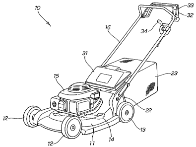
[0033] FIG. 1 is a perspective view of a lawn nuower according
to a first embodiment of the present invention;
[0034] FIG. 2 is a left side view of the lawn mower shown in
FIG. 1;
[0035] FIG. 3 is an enlarged plan view of the lawn mower shown
in FIG. 2;
[0036] FIG. 4 is an enlarged bottom view of the lawn mower shown
in FIG. 2;
[0037] FIG. 5 is a cross-sectional view of line 5 - 5 in FIG.
4;
[0038] FIG. 6 is a cross-sectional view of line 6 - 6 in FIG.
4;
[0039] FIG. 7A is a perspective view of a rear guide end of a
guide shown in FIG. 4; and FIG. 7B is a cross-sectional view
illustrating the relationship of the rear guide end with a housing;
[0040] FIG. 8 is an enlarged cross-sectional view taken,along
line 8 - 8 in FIG. 3;
[0041] FIG. 9 is a perspective view of the housing, an opening
control lever and surrounding parts according to the first
-11-
CA 02634124 2008-06-27
embodiment;
[0042] FIG. 10 is a cross-sectional view illustrating the
relationship among the housing, a cutting blade, a passage opening
of a grass discharge passage and a shutter according to the present
invention, the passage opening being closed by a shutter member;
[0043] FIG. 11 is a cross-sectional view illustrating the
shutter member put in an intermediate mode from the state in FIG.
10;
[0044] FIG. 12 is a cross-sectional view of the shutter member
brought into a fully-opened state from the state shown in FIG_
11;
[0045] FIG. 13 is a perspective view illustrating the shutter
in a fully-closed state;
[0046] FIG. 14 is a perspective view illustrating the shutter
in a half-opened state;
[0047] FIG. 15 is a perspective view illustrating the shutter
in the fully-opened state;
[0048] FIG. 16 is a left side view of a lawn mwer according
to a second embodiment of the present invention;
(0049] FIG. 17 is a plan view of the lawn mower shown in FIG.
16;
[00601 FIG. 18 is a bottom view of the lawn mower shown in FIG.
16;
[0051] FIG. 19 is a cross-sectional view of line 19 - 19 in FIG.
26 18;
[0052] FIG. 20 is a cross-sectional view of line 20 - 20 in FIG.
19;
-12-
CA 02634124 2008-06-27
[0053] FIG. 21 is a perspective view of a plug member according
to the second embodiment of the present invention; and
[0054] FIG. 22 is a cross-sectional view corresponding to FIG.
19, illustrating a state in a bagging mode in which a grass
discharge passage is opened.
DETAILED DESCRIPTION OF THE PREFERRED EMBODIMENTS
[0055] Initial reference is made to FIGS. 1 to 15 illustrating
a first embodiment of a lawn mower of the present invention..
[0056] xn FzG. 1, a lawn mower 10 of this embodiment has a housing
11 as a body, left and right front wheels 12, 12 provided at the
front of the housing 11, and left and right rear wheels 13, 13
as dri.ving wheels provided at the rear of the housing 11 (Only
the left ones of the left and right ones are shown in the figure. ).
The lawn mower 10 further has a single grass cutting blade 14
provided in a central portion within the housing 11, an engine
15 provided on the top of the housing 11 for driving the rear wheels
13, 13 and the cutting blade 14, and a continuously variable
transmission (not shown) interposed between the engine 15 and the
rear wheels 13, 13 within the rear of the housing 11. An operating
handle 16 extends rearward from the housing 11. The lawn mower
10 is a walk-behind self-propelled working machine.
[0057] As shown in FIG. 2, an output shaft 15a extends downward
from the engine 15 as a power source. Bel.ow the engine 15 is
provided the housing 11 opening downward. The cutting blade 14
housed in the housing 11 is attached to the output shaft 15a. A
grass discharge passage 21 with a substantially rectangular cross
section extends from the housing 11 rearward and upward. At an
-13-
CA 02634124 2008-06-27
outlet of the grass discharge passage 21 is provided a receptacle
mounted portion 22. A grass receptacle 23 such as a grass bag is
removably mounted to the receptacle mounted portion 22 (that is,
to the outlet of the grass discharge passage 21) so as to receive
grass cut by the cutting blade 14 (hereinafter referred to as "grass
clippings") through the grass discharge passage 21 in the grass
receptacle 23.
[0058] A receptacle cover 31 is attached to a rear upper portion
of the housing 11 in an upwardly and downwardly swingable manner.
A cutting blade clutch lever 32, a drive clutch lever 33 and a
speed change lever 34 are provided on the operating handle 16.
[OOs9] As shown in FIG. 3, the cutting blade 14 rotates in a
clockwise direction as shown by an arrow Ra to cut grass and also
to produce an air flow as shown by a hollow arrow Rb, that is,
a swirling flow (carrying flow) within the housing 11, transmitting
grass clippings into the grass receptacle 23. The lawn mower 10
is self-propelled forward to proceed with the grass cutting
operation.
[0060] As shown in FIG. 4, the lawn mower 10 of this embodiment
is characterized in that a shutter 40 is provided to a passage
opening 24 facing the housing 11 of the grass discharge passage
21 so that the degree of opening of the passage opening 24 is
adjusted with the shutter 40. That is, the shutter 40 is a member
for opening and blocking the grass discharge passage 21.
[0061] The housing 11 is a spiral case or scroll case with a
scroll portion lid, that is, a bagging-mode housing for allowing
grass clippings to swirl within the housing while directing them
-14-
CA 02634124 2008-06-27
to the grass discharge passage 21 as shown by the hollow arrow
Rb.
[0062] More specifically, the housing 11 has an outer tubular
portion 11b and an inner tubular portion 11c with a diameter smaller
than that of the outer tubular portion llb, which are cylindrical
in shape, being disposed concentrically with the shaft center SC
of the output shaft 15a. The grass discharge passage 21 is
extended rearward from the outer tubular portion llb,tangentially
to the outer tubular portion llb.
[0063] The scroll portion lld is a space enclosed by a top plate
lla, the outer tubular portion llb and the inner tubular portion
lic, conuRUnicating with the passage opening 24 facing the housing
11 of the grass discharge passage 21.
[0064] The housing 11 allows glass clippings to sufficiently
16 swirl with a swirling flow within the housing 11 as shown by hollow
arrows Rc, to provide an efficient mulching-mode operation.
[0065] More specifically, a guide 70 is placed along the scroll
portion lid, being provided beneath the top plate 11a of the housing
11, and a rear guide end 71 of the guide 70 is oriented to face
(that is, opposed to) the passage opening 24.
[0066] Reference numeral 72 denotes a front guide portion of
the guide 70, and 81 a scroll plate.
[0067] As is also apparent from FIG. 4, the lawn mower 10 allows
the guide 70 and the scroll plate 81 to be disposed along the scroll
portion lld with space on the opposite sides of the passage opening
24.
[006s] The height of the guide 70 and the scroll plate 81 within
-15-
CA 02634124 2008-06-27
the scroll portion lld is substantially the same. Changes in the
cross section of the scroll portion iid (changes in the
cross-sectional shape and dimension) are thus relatively small
despite the provision of the grass discharge passage 21 to the
housing 11. As a result, the scroll portion lld allows smooth and
sufficient swirling of air and grass clippings.
[0069] As shown in FIG. 5, the grass discharge passage 21 is
extended rearward and upward from the housing 11 in the location
of the scroll l ld, and the receptacle mounted portion 22 is provided
at the outlet of the grass discharge passage 21.
[oor10] More specifically, the grass discharge passage 21 has
a substantially rectangular cross section, including a top late
21a extended rearward and upward from a middle portion of the top
plate lla of the housing 11, a bottom plate 21b extended rearward
and upward from a middle height of the outer tubular portion llb
of the housing 11, and left and right side plates 21c, 21c between
the top plate 21a and the bottom plate 21b (only the right side
plate 21c is shown in this figure).
[0071] The "passage opening 24 facing the housing 11 of the grass
discharge passage 21" indicates an opening enclosed with a proximal
end portion of the top plate 21a, a proximal end portion of the
bottom plate 21b and proximal end portions of the left and right
side plates (left and right vertical walls) 21c, 21c, relative
to the housing 11.
[0072] As is clear from the above, since the bottom plate 21b
is absent at a portion of the passage opening 24 of the grass
discharge passage 21, the portion has a downwardly-opening
-16-
CA 02634124 2008-06-27
channel-shaped cross section (a substantially U-shaped cross
section opening downward) instead of the substantially
rectangular cross section.
[0073] The bottom of the passage opening 24, that is, a proximal
end 21d of the bottom plate 21b relative to the outer tubular
portion lib is lower in level than the top plate lla of the housing
11 as is obvious.
[0074] In the mulching mode, the lawn mower 10 causes grass cut
by the cutting blade 14 (see FIG. 4) to swirl upward with the cutting
blade 14 within the scroll portion lid, cutting more finely the
grass clippings falling after reaching near the top plate 21a with
the cutting blade 14, and discharging them downward of the housing
11.
[0075) In the bagging mode and the intermediate mode, the lawn
mower 10 also causes grass clippings to swirl upward with the
cutting blade 14 within the scroll portion 11d as will be understood.
The above-described configuration of a portion of the passage
opening 24 of the grass discharge passage 21 facilitates the
entering of swirling grass clippings from the passage opening 24
into the grass discharge passage 21 as shown by arrows in the
bagging mode or intermediate mode with the shutter 40 opened.
[0076] Reference numeral 21e denotes a proximal end portion of
the top plate 12a relative to the top plate lla.
[0077] This figure further illustrates that the guide 70 is
provided below the top plate lla with a certain clearance within
the scroll portion lld, and the height of the rear guide end 71
of the guide 70 is set larger by a height H1 than that of the bottom
-17-
CA 02634124 2008-06-27
of the passage opening 24.
[OOr78] The height of the rear guide end 71 of the guide 70 for
directing grass clippings toward the grass discharge passage 21
set larger than that of the bottom of the passage opening 24
facilitates taking grass clippings swirling along the guide 70
into the grass discharge passage 21 in the intermediate mde. As
a result, a required amount of grass clippings can be securely
received through the grass discharge passage 21 in the grass
receptacle 23 (see FIG. 1). The ratio between the amount of glass
clippings to be received in the grass receptacle 23 and the ammount
of grass clippings to be discharged downward of the housing 11
can thus be relatively precisely set in the intermediate mode.
The workability in the intermediate mode can be further improved.
[0079] Now, with reference to FIGS. 4 and 5, the configuration
of the housing 11 will be summarized.
[00801 The housing 11 has the scroll portion lid in a scroll
shape connected to the passage opening 24 of the grass discharge
passage 21 extending rearward and upward. The top plate lla is
thus formed higher in level as extending in a spiraling direction
of the scroll portion 11d (in the direction of the hollow arrows
Rc in FIG. 4), that is, formed deeper rearward of the paper of
FIG. 4.
[0081) In other words, as shown in FIG. 4, the height of the
top plate lla at the scroll portion lld is smallest at a portion
where the scroll plate 81 is provided, becomes larger as extending
in the direction of the hollow arrows Rc, and is largest at a portion
connected to the passage opening 24.
-18-
CA 02634124 2008-06-27
[0082] In this embodiment, a portion of the scroll portion 17.d
provided with the scroll plate 81 is referred to as a"portion
without the scroll portion" and the remaining portion without the
scroll plate 81 is referred to as a "portion with the scroll
portion."
[0083] In this embodiment, the guide 70 is placed along the
scroll portion lid for allowing grass clippings to swirl within
the bagging-mode housing 11 while directing them toward the grass
discharge passage 21, the guide 70 is provided beneath the top
plate lla of the housing 11, and the rear guide end 71 of the guide
70 is opposed to the passage opening 24, so that the flow direction
Rc (the direction of the hollow arrows Rc) of an air f low swirling
grass clippings within the housing 11, that is, a swirling flow
can be gradually changed and guided toward the passage opening
24 with the guide 70.
[00"] Furthermore, since the guide 70 placed along the scroll
portion lid is provided beneath the top plate lla of the
bagging-mode housing 11, the cross-sectional area of the housing
11 can be gradually changed between a portion with the scroll
portion lid and a portion without the scroll portion lid. The
gradual change of the cross-sectional area results in a gradual
change of the flow velocity of a swirling flow between aportion
with the scroll portion lid and a portion without the scroll portion
lid.
[0085] Thus, in the mulching mode in which the grass discharge
passage 21 is blocked off, a swirling flow guided with the guide
70 smoothly continues swirling within the housing 11. Grass
-19-
CA 02634124 2008-06-27
clippings thus hardly accumulate within the housing 11. No
accumulation of grass clippings allows continuous grass cutting
operations. This results in an increased efficiency in
mulching-mode operations. Further, grass clippings can be evenly
discharged downward from the housing 11. The return amount of
grass clippings returned from the housing 11 to the lawn is thus
even, improving the finished quality of the grass cutting.
[0086] In the bagging mode with the grass discharge passage 21
opened, a swirling flow (carrying flow) guided by the guide 70
flows from the passage opening 24 into the grass discharge passage
21 to discharge grass clippings into the grass receptacle 23. The
operating efficiency in the bagging mode can be secured.
[0087] In this manner, the operating efficiency in the mulching
mode can be i,mproved with the operating efficiency in the bagging
16 mode being secured, improving the finished quality of grass
cutting.
[0088] As shown in FIG. 6, the guide 70 is secured to the housing
11 with a plurality of bolts 75.
[0089] FIGS. 7A and 7B are structural diagrams of the rear guide
end 71 of the guide 70 and surroundings; FIG. 7A is a perspective
view of the rear guide end 71 of the guide 70 in a flat plate,
taken from below; and FIG. 7B is a cross-sectional view of the
relationship of the rear guide end 71 with the housing 11, taken
from the side. FIG. 7A illustrates that the rear guide end 71 of
the guide 70 of a flat plate has a plurality of depressions 71a
and a plurality of projections 71b which are alternately arranged
across the plate in a wave shape_
-20-
CA 02634124 2008-06-27
[0090] When the cutting blade 14 (see FIG. 4) is rotated, an
air flow is generally produced along the guide 70 below the guide
70. This flow tends to become a vortex flow at the rear guide end
71. When the vortex flow is excessive, grass clippings are likely
to be drawn into the vortex flow. As a result, in the bagging mode
or the intermediate mode, the grass clippings have difficulty in
flowing into the passage opening 24 (see FIG. 4).
[0091] In the present embodiment, the wave-shaped rear guide
end 71 of the guide 70 causes interference between air flows Wi
at the depressions 71a in the wave shape and air flows W2 at the
projections 71b to reduce the generation of vortex flows,
straightening an air flow flowing into the passage opening 24.
As a result, in the bagging mode or the intermediate mode, grass
clippings more easily flow into the passage opening 24. Grass
clippings are thus allowed to smothly flow into the grass
receptacle 23 (see FIG. 1) through the grass discharge passage
21 (see FIG. 4) to be more securely received.
[0092] FIG. 8 is a cross-sectional view of line 8 - 8 in FIG.
3. The shutter 40 includes a vertically-extending rotary shaft
44 provided in the vicinity of the passage opening 24, adjacent
either of the left and right side plates 21c of the grass discharge
passage 21, that is, either of the left and right vertical walls
21c, a vertical shield 45 of a vertical plate attached at its swing
proximal end to the rotary shaft 44 for opening and closing the
passage opening 24 by swinging operation, a horizontal shield 46
of a horizontal plate extending from the bottom of the vertical
shield 45 toward the receptacle mounted portion 22 (see FIG. 5)
-21-
CA 02634124 2008-06-27
for blocking a lower portion of the passage opening, and an opening
control lever 53 (control lever 53) coupled to the rotary shaft
44. The shutter 40 can be swung with the opening control lever
53.
5[0093] More specifically, the shutter 40 has a lower bearing
42 attached to a lower portion of the left side plate 21c of the
grass discharge passage 21 with a support bracket 41, and an upper
bearing 43 attached to the top plate 21a of the grass discharge
passage 21. The upper and lower bearings 42 and 43 rotatably
support the rotary shaft 44. The vertical shield 45 and the
horizontal shield 46 are attached to the rotary shaft 44.
(0094] As is also apparent from the figure, the grass discharge
passage 21 and the shutter 40 are higher in level than the cutting
blade 14. The cutting blade 14 even rotated cannot interfere with
16 the grass discharge passage 21 and the shutter 40.
[0095] The rotary shaft 44 has at its distal end the opening
control lever 5 3 attached thereto vertically swingably while being
controlled in its horizontal swing, the opening control lever 53
being resiliently biased with a return spring 54 such as a torsion
spring to a neutral position (a location notch 56b )'shown by solid
lines. The vertical shield 45 and the horizontal shield 46 are
formed by bending a plate material in a substantially L shape in
a side view, forming an integrally-formed shutter member 47. The
rotary shaft 44 is rotated with the opening control lever 53 to
allow the shutter member 47 to swing vertically to the paper of
this figure.
[OOg6] FXG. 9 is a perspective view of the housing, the openxng
-22-
CA 02634124 2008-06-27
control lever and surrounding parts according to the present
embodiment, illustrating that a control guide 56 is provided on'
a rear upper surf ace of the housing 11 and the control guide 56
guides the control of the opening control lever 53.
[pK)97] The control guide 56 has a horizontally-elongated
guiding long hole 56a for inserting the opening control lever 53
therethrough and a plurality of vertically-elongated-location
notches 56b arranged along the guiding long hole 56a. The location
notches 56b each extend downward from the guiding long hole 56a.
Reference numeral 55 denotes a grip.
[0098) FIG. 10 is a plan view illustrating the relationship
among the housing, the cutting blade, the passage opening of the
grass discharge passage and the shutter according to the present
invention, illustrating that the shutter member 47 provided in
the grass discharge passage 21 allows the passage opening 24 to
be opened and closed.
[0099] As is clear from the figure, the proximal end of the right
side plate 21c of the grass discharge passage 21 is tangential
to the outer tubular portion llb, and the proximal end of the left
side plate 21c is tangential to the inner tubular portion Ilc.
[0100] As described above, the passage opening 24 of the grass
discharge passage 21 is enclosed with the proximal end 21e of the
top plate 21a (see FIG. 5), the proxaimal end portion of the bottom
plate 21b and the proximal end portions of the left and right side
plates 21c, 21c, relative to the housing 11, being an opening
portion in a substantially crescent shape in a plan view. At the
opening portion, the rotary shaft 44 and the vertical shield 45
-23-
CA 02634124 2008-06-27
are disposed as shown in FIG. 10. This arrangement allows a more
smooth flow of grass clippings in the bagging mode in which the
vertical shield 45 is-fully opened or in the intermediate mode
in which the vertical shield 45 is half opened.
6 [0101] In the mulching mode in which the vertical shield 45 is
fully closed, however, the grass discharge passage 21 conanunicates
with the scroll portion lld via the passage opening 24. This
reduces by half the effect of closing the vertical shield 45. To
prevent this is provided the horizontal shield 46 of a horizontal
plate extending from the bottom of the vertical shield 45 toward
the receptacle mounted portion 22 for closing a lower portion of
the passage opening 24. This results in an increased shielding
efficiency in shielding the grass discharge passage 21 against
the scroll portion lid with the vertical shield 45 fully closed.
[0] In this manner, operations in the bagging mode, mulching
mode and intermediate mQde can be more efficiently performed with
the single housing 11.
[0102] The control guide 56 is a member serving as a guide for
the opening control lever 53 when the degree of opening of the
shutter 40 is controlled, having, e.g., fi.ve location notches 56b.
The location of the location notch 56b facing one end of the guiding
long hole 56a defines a full-close position and the location of
the location notch 56b facing the other end of the guiding long
hole 56a defines a full-open position. The spacing between
26 adjacent location notches 56b may be set to correspond to a 25%
opening of the shutter 40.
[0103] Now, the function of the lawn mower 10 of the above
- 24 -
CA 02634124 2008-06-27
structure will be described with reference to FIGS. 10 to 15.
[0104] FIG. 10 illustrates that the opening control lever 53
is put in the full-close position to put the shutter member 47
in a full-close position (0% opening). Closing the passage
opening 24 with the shutter member 47 allows the lawn mower 10
to be set in a form for use in the mulching mode. A portion of
the passage opening 24 is closed by the horizontal shield 46.
[0105] In this state, grass clippings swirl below the passage
opening 24 in a direction of arrows within the housing 11, that
is, within the scroll portion lld. As a result, the grass
clippings can be cut more finely by the cutting blade 14 within
the housing 11 and discharged downward of the housing 11. From
this state, the shutter member 47 can be swung clockwise in the
figure to be opened.
[0106] FIG. 11 illustrates that the opening control. lever 53
is put in a half-open position to put the shutter member 47 in
a half-open position (50% opening). opening the passage opening
24 by a desired degree of opening with the shutter member 47 allows
the lawn nwwer 10 to be set in a form for use in the intermediate
mode (mode intermediate between the bagging mode and the mulching
mode), returning part of grass cut by the cutting blade 14 to the
ground and receiving the rest in the grass receptacle 23 (see FIG.
1). Also in this mode, a portion of the passage opening 24 is closed
by the horizontal shield 46.
[0107] FIG. 12 illustrates that the opening control, lever 53
is put in the full-open position to put the shutter member 47 in
a full-open position (100% opening). With the shutter member 47
-25-
CA 02634124 2008-06-27
put in the full-open position, the vertical shield 45 is adjacent
an inner surface of the left side plate 21c. Full opening of the
passage opening 24 allows the lawn mower 10 to be set in a form
for use in the bagging mode and receive grass cut by the cutting
blade 14 in the grass receptacle 23 (see FIG. 1).
[0108] In this manner, the shutter 40 is provided at the passage
opening 24 facing the housing 11 of the grass discharge passage
21 extending rearward from the downward-opening housing 11. The
shutter 40 consists of the vertically-extending rotary shaft 44
provided in the vicinity of the passage opening 24, adjacent either
of the left and right verticalwalls 21c of the grass discharge
passage 21, the vertical shield 45 of a vertical plate attached
at its swing proximal end to the rotary shaft 44 for opening and
closing the passage opening 24 by swinging operation, the
horizontal shield 46 of a horizontal plate extending from the
bottom of the vertical shield 45 toward the receptacle mounted
portion 22 for closing the lower portion of the passage opening
24, and the opening control lever 53 coupled to the rotary shaft
44, so that the degree of opening of the passage opening 24 can
be desirably adjusted with the shutter 40.
[0109] Only controlling the opening of the shutter 40 with a
simple configuration allows switching between the bagging mode
in which the shutter 40 is fully opened to receive grass clippings
in the grass receptacle 23 (see FIG. 1) , the mulching mode in which
the shutter 40 is fully closed to discharge grass clippings
downward of the housing 11, and the intermediate mode between the
bagging mode and the mulching mode in which the shutter 40 is opened
-26-
CA 02634124 2008-06-27
to a desired degree. It is needless to change parts every time
the mode is switched.
[0110] Further, opening the shutter 40 to a desired degree
allows minute and preferable setting of the form of discharge of
grass clippings, according to lawn conditions, required finished
quality, or preference. Furthermore, switching to the
intermediate mode allows the reduction of the discharged flow
amount of grass clippings discharged from the housing 11 to the
grass receptacle 23. This results in a lengthened time during
which grass clippings accumulate in the grass receptacle 23,
reducing the frequency of replacement of the grass receptacle 23.
[03l1] For efficient operations in the bagging mode, the scroll
portion lld is provided in the housing il for allowing grass
clippings to swirl within the housing 11 while directing them to
the grass discharge passage 21. Also for efficient operations in
the mulching mode, the guide 70 is placed along the scroll portion
Ild, being provided beneath the top plate lla of the housing 11,
and the rear guide end 71 of the guide 70 is opposed to the passage
opening 24.
[0112] Thus, when the shutter is opened as shown in FIG. 12,
the scroll portion lid and the guide 70 (see FIG. 5) allow grass
clippings to swirl while being smmoothly guided to the passage
opening 24.
[0113] When the shutter 40 is closed as shown in FIG. 10, grass
clippings swirling in the scroll portion lld can be guided by the
guide plate 70 (see FIG. 5) to s7noothly flow along the shutter
40 in the closed state. The same is true in the intermediate mode.
-27-
CA 02634124 2008-06-27
(0114) In this manner, operations in the bagging mode, mulching
mode and intermediate mode can be more efficiently performed with
the single housing 11.
(0115] The housing 11 has, as described above, the outer tubular
portion llb and the inner tubular portion lic which are cylindrical
about the shaft center SC (see FIG. 4). The grass discharge
passage 21 is extended tangentially to the outer tubular portion
lib. The shutter 40 is provided at the passage opening 24 facing
the housing 11. The direction of the grass discharge passage 21
extending from the outer tubular portion 11b agrees with a rotation
direction Ra of the cutting blade 14. In other words, the grass
discharge passage 21 extends tangentially to the rotating path
of the cutting blade 14. The passage opening 24 opens in the
rotation direction Ra of the cutting blade 14.
[0116] The outer side plate 21c of the grass discharge passage
21 extends tangentially to the outer tubular portion lib and the
inner side plate 21c extends tangentially to the inner tubular
portion 11c. The rotary shaft 44 of the shutter 40 is disposed
in the vicinity of the inner side plate 21c. The swing distal end
of the shutter member 47 thus faces the outer side plate 21c. The
shutter member 47 opens in the rotation direction Ra of the cutting
blade 14. As will be understood, when the vertical shield 45 of
the shutter 47 is opened at a certain angle, the amount of
displacement of the swing distal end of the vertical shield 45
is greater than the amount of displacement of the swing proximal
end. When the vertical shield 45 is opened at a certain angle,
a greatly-displaced peripheral portion of the vertical shield 45
-28-
CA 02634124 2008-06-27
can thus relatively largely open the passage opening 24.
[0117] The swirling velocity of grass clippings swirling within
the housing 11 by the rotation of the cutting blade 14 is higher
as being farther from the shaft center SC.
[0118] As is apparent from the above, when the passage opening
24 of the grass discharge passage 21 extending tangentially to
the outer tubular portion llb is opened to some degree (more than
0% and less than 100% opening) with the vertical shield 45 in the
intermediate mode, grass clippings swirling at a high velocity
through the periphery of the housing 11 easily flow from the passage
opening 24 into the grass discharge passage 21. This results in
an increased efficiency in the reception of grass clippings in
the intermediate mode.
[0119] FIG. 13 is a view of the lawn mower 10 with the shutter
40 in a full-close position, taken from the side of the receptacle
mounted portion 22.
(0120] FIG. 14 is a view of the lawn mower 10 with the shutter
40 in a half-open position, taken from the side of the receptacle
mounted portion 22.
[012x] FIG. 15 is a view of the lawn mower 10 with the shutter
40 in a full-open position, taken from the side of the receptacle
mounted portion 22.
[0122] Now a lawn mower according to a second embodiment of the
present invention will be described with reference to FIGS. 16
to 22. Components identical to those in the first embodiment shown
in FIGS. 1 to 15 are affixed the same reference numerals and will
not be described.
-29-
CA 02634124 2008-06-27
[0123] As shown in FIGS. 16, 17 and 18, a lawn mower 100 modif ied
according to the second embodiment is characterized in that an
openable and closable lid 101 is provided at an outlet of a grass
discharge passage 21, a member for opening and blocking the grass
discharge passage 21 is a plug member 180 (plug) to be removed
out of or inserted into the grass discharge passage 21, and a guide
170 is provided at a scroll portion lid.
[0124] The lawn mower 100 of the second embodiment has, as shown
in FIG. 18, in order to ef ficiently perform bagging-mode operations,
the scroll portion lld provided to the housing 11 for allowing
grass clippings to swirl within the housing 11 while directing
them to the grass discharge passage 21, and has, in order to
efficiently perform mulching-mode operations, the guide 170
placed along the scroll portion lid, being provided beneath a top
plate lla of the housing 11, and a rear guide end 171 of the guide
170 opposed to a passage opening 24. The configurations of the
corciponents will be described in detail below.
[O125] The plug member 180 extends toward the rear guide end
171 of the guide 170 within the housing 11. More specifically,
the plug member 180 inserted f rom the outlet (right in the figure )
of the grass discharge passage 21 is protruded from the passage
opening 24 into the scroll portion lid, and a distal end 181 thereof
is extended in a curve along the scroll portion lid to the vicinity
of the rear guide end 171, to be opposed to the rear guide end
171.
[0126] FIG. 19 illustrates that the grass discharge passage 21
is extended rearraard and upward from the housing 11 in the location
-30-
CA 02634124 2008-06-27
of the scroll portion IId and a receptacle mounted portion 22 is
provided at the outlet of the grass discharge passage 21.
[0127] This figure also illustrates that the guide 170 is
provided in the scroll portion lid below the top plate lla with
a certain clearance and the rear guide end 171 of the guide 170
is generally oriented toward the bottom of the passage opening
24, that is, a proximal end 21d of a bottom plate 21b. Ref erence
sign Li is an orientation line in which the rear guide end 71 is
directed toward the bottom of the passage opening 24.
[0128] The plug member 180 is characterized in that a lower end
182 thereof is placed at a height substantially identical to that
of the rear guide end 171, that is, in the orientation line Li.
[0129] The lid 101 is closed after a grass receptacle 23 shown
in imaginary lines is removed and the plug znember 18 is put into
the grass discharge passage 21. Closing the outlet of the grass
discharge passage 21 can prevent the dislocation of the plug member
180.
[0130] Now, the configuration of the housing 11 and the scroll
portion lid will be described with reference to FIGS. 18 and 19.
[0131] The scroll portion lld according to the second embodiment
is a space enclosed with the top plate I la, an outer tubular portion
lib, and a scroll-shaped inner wall lle formed radially outward
of an inner tubular portion llc, and connected to the passage
opening 24 facing the housing 11 of the grass discharge passage
21.
[0132] The housing 11 has the scroll portion lid in a scroll
shape connected to the passage opening 24 of the grass discharge
-31-
CA 02634124 2008-06-27
passage 21 extending rearward and upward. The top plate 1].a is
thus formed higher in level as extending in a spiraling direction
of the scroll portion lid (in the direction of hollow arrows Rc
in FIG. 18), that is, formed deeper rearward of the paper of FIG.
18.
[0133] In other words, as shown in FIG. 18, the height of the
top plate lla of the scroll portion lld is smallest at a scroll
proxi.mal end portion llf, becomes larger as extending in the
direction of the hollow arrows Rc, and is largest at a portion
connected to the passage opening 24.
[0134] In this embodiment, a portion extending from the scroll
proximal end portion llf in the direction of the hollow arrows
Rc to be connected to the passage opening 24 is referred to as
a "portion with the scroll portion." A portion extending from the
portion connected to the passage opening 24 in the direction of
the hollow arrows Rc to the scroll proximal end portion llf is
a "portion llg without the scroll portion lld."
[0135] FIG. 20 illustrates that the guide 170 is secured to the
housing 11 with a plurality of bolts 175.
[0I36] As shown in FIG. 21, the plug member 180 is integrally
formed with a bottom plate 183, a side plate 184 extending upward
from one side of the bottom plate 183 and a tab 185 extending upward
from a central portion of the bottom plate 183.
[0137] Now, the function of the second embodiment of the above
structure will be described with reference to FIGS. 18, 19 and
22.
[0138] As shown in FIGS. 18 and 19, the lawn mower 100 of the
-32-
CA 02634124 2008-06-27
second embodiment has the guide 170 placed along the scroll portion
lld for allowing grass clippings to swirl within the bagging-mode
housing 11 while directing them toward the grass discharge passage
21, the guide 70 being provided beneath the top plate lla of the
housing 11, and the rear guide end 171 of the guide 170 being opposed
to the passage opening 24, so that the direction Rc (the direction
of the hollow arrows Rc) of an air flow swirling grass clippings
within the housing, that is, a swirling flow can be gradually
changed and guided toward the passage opening 24 with the guide
170.
[0139] Furthezmore, since the guide 170 placed along the scroll
lid is provided beneath the top plate lla of the bagging mode
housing 11, the cross-sectional area of the housing 11 can be
gradually changed between the portion with the scroll portion lld
and the portion llg without the scroll portion lld. The gradual
change of the cross-sectional area results in a gradual change
of the flow velocity of a swirling flow between the portion with
the scroll portion lid and the portion llg without the scroll
portion lld.
[0140] Thus in the mulching mode in which the grass discharge
passage 21 is blocked off, a swirling flow guided by the guide
70 smoothly continues swirling within the housing 11. Grass
clippings therefore hardly accumulate within the housing 11. No
accumulation of grass clippings allows continuous grass cutting
operations. As a result, the. operating efficiency in the
mulching-mode is increased. Further, grass clippings can be
evenly discharged downward from the housing 11. The return amount
-33-
CA 02634124 2008-06-27
of the grass clippings returned from the housing 11 to the lawn
is thus even, improving the finished quality of grass cutting.
[0141] In the bagging mode with the grass discharge passage 21
opened, a swirling flow (carrying flow) guided by the guide 170
flows from the passage opening 24 into the grass discharge passage
21 to discharge grass clippings into the grass receptacle 23 as
shown in FIG. 22. The operating efficiency in the bagging mode
can be secured.
[0142] In this manner, the operating efficiency in the mulching
mode can be improved with the operating efficiency in the bagging
mode secured, itYtproving the finished quality of grass cutting.
[0143] Further, as shown in FIGS. 18 and 19, the rear guide end
171 of the guide 170 is generally oriented toward the bottom of
the passage opening 24, that is, the proximal end 21d of the bottom
plate 21b, so that the flow direction Rc of a swirling flow can
be gradually changed and guided below the passage opening 24. The
cross-sectional area of the housing 11 can thus be more gradually
changed between the portion with the scroll portion 11d and the
portion llg without the scroll portion lid. The more gradual
change in the cross-sectional area results in a more gradual change
in the flow velocity of the swirling flow between the portion with
the scroll portion lid and the portion llg without the scroll
portion lld.
[0144] As a result, in the mulching mode, a swirling flow guided
by the guide 170 more smoothly continues swirling within the
housing 11. Local accumulation of grass clippings within the
housing 11 can thus be further prevented. More continuous grass
-34-
CA 02634124 2008-06-27
cutting operations can thus be performed, further increasing
operating efficiency in the mulching mode. Also the return znount
of grass clippings returned from the housing 11 to the lawn can
be more evened, further improving the finished quality of grass
cutting.
[0145] Furthermore, the fact that a member for opening and
closing the grass discharge passage 21 is constituted by the plug
member 180 to be removed out of or inserted into the grass discharge
passage 21 and the plug member 180 is extended toward the rear
guide end 171 of the guide 170 within the housing 11 allows the
bagging-mode housing 11 to be switched between the bagging mode
and the mulching mode only by removing or inserting the plug member
180 out of or into the grass discharge passage 21. The mode
switching operation is easy and allows short-time switching.
[0146] The lower end 182 of the plug member 180 extended toward
the rear guide end 171 of the guide 170 is placed at a height
substantially identical to that of the rear guide end 171, so that
a swirling flow guided by the guide 170 passes below the plug member
180 in the mulching mode with the grass discharge passage 21 blocked
by the plug member 180. In this manner, a swirling flow guided
by the guide 170 can be further gradually changed and guided toward
the portion llg without the scroll portion lid by the lower end
182 of the plug member 180.
[0147] The cross-sectional area of the housing 11 can thus be
26 more gradually changed between the portion with the scroll portion
lld and the portion llg without the scroll portion lid. The more
gradual change in cross-sectional area results in a more gradual
-35-
CA 02634124 2008-06-27
change in the flow velocity of a swirling flow between the portion
with the scroll portion lid and the portion llg without the scroll
portion lld. As a result, in the mulching mmode, a swirling flow
guided by the guide 170 more smoothly continues swirling within
the housing 11. Grass clippings can thus be further prevented from
locally accumulating within the housing 11.
[0148] In the present invention, the power source is not limited
to the engine 11 and may be an electric motor, for example.
(0149) The grass receptacle 23 is not limited to a grass bag
and may be a box, for example.
101501 The vertical shield 45 and the horizontal shield 46 may
have any shape, size and material as long as being configured to
be able to control the degree of opening of the passage opening
24.
[0151] The shutter member 47 may have the swing proximal end
of the vertical shield 45 attached to the rotary shaft 44 in any
manner, including the configuration in which only the swing
proximal end of the vertical shield 45 is attached to the rotary
shaft 44 or only the swing proximal end of the horizontal shield
46 is attached to the rotary shaft 44, for example.
[0152] The guide 71 or 170 may have any shape, size and matexi.al.
[0153] The rear guide end 71 may have any shape and size of the
depressions 71a and the projections 71b as long as being in a wave
shape.
26 [0154] The present disclosure relates to the subject matters
of Japanese Patent Application No. 2002-087057, filed March 25,
2002, and Japanese Patent Application No. 2002-325846, filed
-36-
CA 02634124 2008-06-27
November 8, 2002.
-37-