Note: Descriptions are shown in the official language in which they were submitted.
CA 02634340 2008-06-19
WO 2007/071258 PCT/DK2006/000742
1
Iniection device
The technical field
The invention relates to a device for an intermittent or continuous
administration of a therapeutical substance, such as insulin, comprising a
base part to which an injection part and a delivery part are fastened. The
delivery part comprises a reservoir and a pump, and the injection part
comprises a body with a through-going opening, and at least one cannula
having a proximal end protruding from the lower side of the body.
Prior art
EP-A1-1.527.792 describes a medical device comprising a transdermal
access unit and a reservoir. The transdermal access unit comprises
transdermal access means for transporting a fluid through a skin portion of a
subject, and a mounting surface adapted for application to the skin of the
subject. The reservoir unit comprises a reservoir adapted to contain a fluid
drug and an outlet allowing the transdermal access means to be arranged in
fluid communication with an interior of the reservoir. Also the device
comprise
means for expelling e.g. a pump which means during use expels a fluid drug
out of the reservoir and through the skin of the subject via the transdermal
access means. The transdermal access unit and the reservoir unit further
comprise releasable mating coupling means allowing the reservoir unit to be
secured to the transdermal access unit during use. The object of the
invention is to provide a skin mountable drug delivery device or system which
allows such a device or system to be used in a convenient and cost-effective
manner.
According to this document the insertion needle (113, 212 or 412) of the
described embodiments is pivotably arranged inside the needle housing and
can be moved between an extended and an extracted position. When the
injection needle is inserted it penetrates a membrane in order to penetrate
the skin of the subject. According to the present invention a subcutaneously
CONFIRMATION COPY
CA 02634340 2008-06-19
WO 2007/071258 PCT/DK2006/000742
2
placed cannula is stationary in relation to the base part of the device where
the base part is somehow adhered to the user.
US 2004/0204673 Al describes a lightweight and low cost fluid delivery
device capable of adjustable and programmable fluid delivery includes a
housing that surrounds a reservoir chamber. In fluid communication with the
reservoir chamber is a dispenser for dispensing the fluid from the reservoir
in
finite amounts. The dispenser is controlled by an electronic microcontroller
of
the fluid delivery device. The fluid delivery device further includes a
communication element that receives information from a remote control
device not mechanically attached to the fluid delivery device of the present
invention. Also included is an exit port assembly in fluid communication with
the dispenser from which the liquid medication exits the fluid delivery device
and enters the body of a mammalian patient transcutaneously.
The housings 702, 802 can each be made from flexible material, or can be
provided with flexible hinged sections that allow the fluid delivery device 10
to
flex during patient movement to prevent detachment and aid in patient
comfort but there are no directions as to how such a hinged section should
be constructed.
The invention
The object of the invention is to provide a device for delivering fluid
including
a pump, a reservoir and an injection part which device assures a fluid tight
connection between the reservoir and the injection part. The devices
according to the present invention are constructed with means to provide an
easy connection and disconnection of the delivery parts to the injection part
and at the same time assure a fluid tight connection and prevent invasion of
microorganisms into the parts of the device. According to a preferred
embodiment of the invention it is also assured that the wearer will have less
discomfort during use of the device as this embodiment has means to reduce
the transferal of actions from the relatively heavy delivering part to the
injection part when the delivering part is affected by touches or movements.
CA 02634340 2008-06-19
WO 2007/071258 PCT/DK2006/000742
3
According to claim I the invention comprises a device for delivering fluid
comprising an injection part and a fluid delivery which fluid delivery part
and
injection part can be separated and rejoined part (3, 4), the fluid delivery
part
comprises a reservoir, transferal means e.g. in form of a pump and a house
and the injection part comprises
- a base plate,
- a cannula part comprising a body with a through going opening provided
with a cannula extending past the proximal side of the base plate and
- means for fixation of the base plate to the skin of the user
wherein the delivery part and the injection part is assembled through a
connector comprising a fluid path leading fluid from the reservoir to the
through-going opening in the cannula part which fluid path comprises means
for blocking access to the injection part when the connector is disconnected
from the delivery part and/or the injection part. According to one embodiment
of the invention the device comprises means for blocking the access to the
delivery part when the connector is separated from this. This embodiment is
normally used when a reservoir of the delivery device can be removed from
the injection part and afterwards mounted again for further use. According to
this or other embodiment the base plate is provided with fastening means for
connecting and disconnecting of the delivery device extending from the distal
side of the base plate.
When the connector is a part of the device it is possible to provide a fluid
tight
connection between the delivery part and the injection part. When
constructing the device with and interconnecting part it is also possible to
add
other advantageous features such as means for reducing impacts transferred
from the heavy delivery part to the injection part which is partly inserted
into
the skin of the user. These features make it more safe and comfortable for
the user to wear the device.
A"reservoir" is the part of a device where the liquid is held, the liquid
being
any kind of medication which has to be delivered to the patient in a certain
CA 02634340 2008-06-19
WO 2007/071258 PCT/DK2006/000742
4
amount at certain time intervals. The "delivery part" is the part of the
device
which holds a liquid storage and assures transport of the liquids to the
injection part. The "injection part" defines a kind of port which is fastened
to
the user's skin and provided with means e.g. a cannula for transferring the
liquid to the user. The injection part does not comprise any heavy or
voluminous parts.
In a preferred embodiment the end openings to the fluid path through the
connector are blocked when the connector is disconnected from the delivery
part and/or the injection part. This feature is directed toward products which
are intended to be used for a longer time which necessitates that the
reservoir can be replaced and e.g. the delivery part can be disconnected.
Preferably the openings to the fluid path through the connector are blocked
with a membrane which can be penetrated by a needlelike object.
In another preferred embodiment the parts of the device have at least two
positions, a first position and a second position, in the first position the
outlet
from the reservoir is blocked with a first barrier which is not permeable for
microorganisms and the inlet of the through going opening in the injection
part is blocked with a second barrier which is not permeable for micro
organisms, in the second position an open fluid connection is formed
between the reservoir and the through going opening in the injection part by
passing the first and the second barrier. One or both of the barriers can
comprise a material which can be penetrated by a needielike object where
the opening close on retraction of the needle like object or one or both of
the
barriers can comprise a hard surface which in one position forms an opening
in the area positioned between the outlet of the outlet pipe and the inlet of
the
through going fluid path and in another position close the through going fluid
path. Preferably the injection part and the delivery part are connected to
each
other by one or more flexible areas. More preferred the connector is
connected to one part by one or more non-flexible connection and connected
to the other part by a flexible area. Most preferred the connector is
connected
to the injection part by a flexible area.
CA 02634340 2008-06-19
WO 2007/071258 PCT/DK2006/000742
In one preferred embodiment the at least one flexible area is constructed of
an area with reduced material dimensions.
5 In another preferred embodiment the at least one flexible area is
constructed
of an area made by a softer and more flexible material.
In a third preferred embodiment the at least one flexible area is constructed
of an area made of a material which by its form has an ability for extension
and compression such as a material being pleated or folded.
Preferably the injection part and the delivery part are not connected to each
other by non-flexible or rigid areas as this would reduce the effect of the
flexible areas. That the injection part and the delivery part are not
connected
to each other by non-flexible or rigid areas means that only flexible areas
connect the injection part and the delivery parts.
In a preferred embodiment the device comprises a base part fastened to the
patient's skin, the delivery part is fastened to a first part of the base part
and
the injection part is fastened to a second part of the base part, one or more
flexible areas are positioned between the first part and the second part of
the
base part. Preferably the delivery part is releasably fastened to the base
part,
and the connector is unreleasably fastened to the base part. Also the
connector is preferably fastened to the first part of the base part and more
preferred the connector is fastened unreleasably to the first part of the base
part with a non-flexible connection. In the described embodiments the base
part is illustrated as a relatively flat part but the "base part" could be any
construction which makes it possible to unite or combine the injection part
and the delivery part into one unit which unit can be worn by the user
directly
fastened to the skin.
When the flexible areas are placed between the relatively heavy delivery
device and the injection device, the transferal of actions from the delivery
CA 02634340 2008-06-19
WO 2007/071258 PCT/DK2006/000742
6
device to the injection device is prevented or at least significantly reduced,
and the injection site of the subcutaneously placed cannula will be protected
from the main part of any interaction resulting from pushing or touching the
delivery part. Often the delivery part is separated physically from the
injection
part by a relatively long tube which prevents the transferal of actions but
when the delivery part is positioned together with the injection device, the
user will feel less discomfort when wearing a device according to the
invention. By using a connector it is possible to avoid the direct contact
between the delivery part and the injection part and at the same time
fastened both parts as one unit to the skin of the user.
The cannula can protrude from the proximal side of the body of the injection
part or from the side of the body. If the cannula protrudes from the side of
the
body as it does in the embodiments shown in fig. 4 and fig. 7, the cannula
will
normally be bending and it would be preferred to use a cannula which is at
least partly formed of a soft and flexible material. If the cannula protrudes
from the proximal side of the body as shown in fig. 12, the cannula can be
made of a hard material such as metal or it can be made of a soft and flexible
material.
According to the invention the connector needle can be one end of a single
needle which at the other end functions as the cannula. When the connector
needle and the cannula is formed as one needle it will normally be made of
metal or hard polymer but it can also be made of e.g. a polymer which is
hardened in the connector end and unhardened and soft in the cannula end.
Also the single needle can be composed of two different materials, a hard
material for the connector end and a relatively soft material for the cannula
end. Also the connector needle and the cannula can be separated into at
least two needies. The injector part can then be provided with a commonly
known soft cannula which cannula can be inserted by the help of an insertion
needle attached to a separate inserter, and the connector needle can be
made of a hard material and fastened to either the injector part or the
delivery
part.
CA 02634340 2008-06-19
WO 2007/071258 PCT/DK2006/000742
7
The flexible areas are constructed of an area with reduced material
dimensions, e.g. openings or cuts can be provided in a material or the
thickness of a material can be reduced, or of an area made by a softer and
more flexible material or it is constructed of an area made of a material
which
by its form or structure has ability for extension and compression such as a
material being pleated or folded.
Preferably access of micro organisms to the reservoir during a non-
connected state, i.e. when the reservoir and the injection part are separated,
is prevented as the opening to the reservoir is blocked when the two parts
separate.
The word "passing" comprise all possible ways to make a flow pass through
or around a barrier, in most of the embodiments of this invention the barrier
is
passed by penetrating the barrier with a needle but there is also an example
(fig. 18A and B) where the barrier is passed by pushing aside a hard cover
thereby creating a flow path.
If the barriers comprise a material which can be penetrated by a needlelike
object, the opening close on retraction of the needle like object. The
needlelike object can be either blunt or sharp-pointed meaning that the
needielike object either pushes its way through the barrier or cuts its way
through the barrier. If one of the barriers comprises a hard surface, i.e. a
non-
penetrable surface, the barrier will have to be moved in order to form an
opening in the area positioned between the outlet of the outlet pipe and the
inlet of the through going fluid path.
In a most preferred embodiment the device is fastened to the patients skin by
applying a mounting pad adhered to the proximal side of the base part or to
the proximal side of the infusion part, the adhering of the mounting pad to
the
base part or infusion part can include glue, Velcro, moulding etc.
CA 02634340 2008-06-19
WO 2007/071258 PCT/DK2006/000742
8
Embodiments of the invention will now be described with reference to the
figures in which:
Figure 1 shows a first embodiment of the invention from above at the B-B line
shown in figure 3, where the delivery part is placed beside the injection
part.
Figure 2 shows an enlarged part, marked with a circle, of the embodiment in
figure 1.
Figure 3 shows the embodiment of figure 1 from the side indicating the line
B-B.
Figure 4 shows the first embodiment where the delivery part is separated
from the injection part.
Figure 5 shows an enlarged part, marked with a circle, of the embodiment in
figure 4.
Figure 6A shows a second embodiment of the invention seen from the side of
the injection part.
Figure 6B shows the same embodiment as in figure 6A seen from the cut
made by the line B-B.
Figure 7 shows an enlarged part, marked with a circle, of the embodiment in
figure 6B. I
Figure 8A shows the injection part and the base part of the second
embodiment separated from the delivery part.
Figure 8B shows an enlarged part, marked with a circle, of the embodiment
in figure 8A.
Figure 9 shows both the delivery part and the injection part of the second
embodiment.
CA 02634340 2008-06-19
WO 2007/071258 PCT/DK2006/000742
9
Figure 10A shows the same embodiment as figure 8A from a different angle.
Figure 10B shows an enlarged part, marked with a circle, of the embodiment
in figure 10A.
Figure 11 shows a third embodiment of a delivery device according to the
invention in a connected state, and in this embodiment the delivery part is
placed on top of the injection part.
Figure 12 shows the third embodiment of the device in a separated state.
Figure 13 shows the two parts of the third embodiment from the upper and
lower side respectively.
Figure 14 shows a fourth embodiment of the delivery device according to the
invention. "A" shows the delivery part with the injection part prepared to be
connected with the delivery part seen from the side, "B" shows the delivery
part from beyond and "C" shows the injection part seen from above.
Figure 15 shows the fourth embodiment seen from the side (line V-V) in a
separated state.
Figure 16 shows the fourth embodiment seen from the side (line V-V) in a
connected state.
Figure 17 shows a fifth embodiment of the delivery device according to the
invention having a fluid tight lock between the delivery part and the
injection
part.
Figures 18A and 18B show an enlarged part of the fifth embodiment in two
states; in the first state the device is closed for fluid flow, in the second
state
the device is open for fluid flow.
Figure 19 shows another embodiment ensuring fluid tight transferal of fluid
from the delivery part to the injection part.
CA 02634340 2008-06-19
WO 2007/071258 PCT/DK2006/000742
Figure 20 shows a sixth embodiment having a base part equipped with a
central connector and peripheral injection part.
Figure 21 shows the delivery device and the base part of the sixth
embodiment in a joined state from above and from the side.
5 Figure 22 shows a cut through view of the sixth embodiment in the joined
state of fig. 21.
Figure 23 shows an enlargement of the connector part of fig. 22.
Figure 24 shows an enlargement of the injector part of fig. 22.
Figure 25 shows a view from below of the delivery part of the sixth
10 embodiment.
Figure 26 shows a seventh embodiment having a base part equipped with a
central combined connector and injection part.
Figure 27 shows the delivery device and the base part of the seventh
embodiment in a joined state from the side and from above.
Figure 28 shows a cut through view of the seventh embodiment in the joined
state of fig. 27 and an enlargement of the combined connector/injection part.
Figure 29 shows a view from below of the delivery part of the seventh
embodiment.
Figure 30 shows an eighth embodiment having a base part equipped with a
central combined connector and injection part where the combined part is
divided into to units.
Figure 31 shows the delivery device and the base part of the eighth
embodiment in a joined state from above and from the side.
CA 02634340 2008-06-19
WO 2007/071258 PCT/DK2006/000742
11
Figure 32 shows a cut through view of the eighth embodiment in the joined
state of fig. 31 and an enlargement of the combined connector/injection part.
Figure 33 shows a ninth embodiment having an oval base part equipped with
a central connector and peripheral injection part.
Figure 34 shows the delivery device and the base part of the ninth
embodiment in a separated state from below and the reservoir and the base
part from the side.
Figure 35 shows the delivery device and the base part of the ninth
embodiment in a joined state from the side and from above.
Figure 36 shows a cut through view of the ninth embodiment in the joined
state of fig. 35 and an enlargement of the injection part.
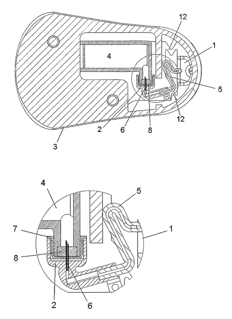
Fig. 1-3 show a first embodiment of the invention where the delivery part and
the injection part are fastened to each other. In fig. 1 the embodiment is
seen
from above at the B-B line shown in fig. 3 and fig. 2 show a small part of
fig. 1
in enlarge form. The device comprises an injection part 1, a connector 2, a
delivery part comprising a pump 3 and a reservoir 4, a flexible tube 5
creating
a fluid connection between the injection part I and the delivery part, a
connector needle 6 which can penetrate both a protective seal 7 covering the
entrance of the connector and a septum 8 covering the entrance of the
reservoir and a cannula 9 which is placed subcutaneously during use. In fig.
1-3 the device is in a connected state where the injection part and the
delivery part are joined together and ready for use.
Fig. 2 shows an enlargement of the connector 2 of fig. 1. In this embodiment
the connector 2 comprises a molded part in a non-flexible material with a
through-going opening which in one end is connected to the flexible tube 5
and in the other end is provided with a connector needle 6. In a state where
the connector 2 is not connected to the reservoir 4, the connector needle 6
extends into a closed room comprising walls formed respectively of a
cylindrical extension of the connector 2 and of the elastic protective seal 7.
In
CA 02634340 2008-06-19
WO 2007/071258 PCT/DK2006/000742
12
the connected state the protective seal 7 is pushed towards the inside wall of
the connector 2 surrounding the connector needle 6 and when connecting
the connector 2 to the reservoir 4 the connector needle 6 first penetrates the
protective seal 7 and then the septum 8 in order to create a passage from the
connector 2 to the inside of the reservoir 4. In this embodiment the connector
2 is fastened unreleasably to a base plate which is an integrated part of the
delivery part 3, 4.
Fig. 3 shows the embodiment of fig. 1 from the side as it would look when the
device is in use. A base plate 10 is placed along the skin of the patient and
fastened to the patient e.g. by an adhesive pad. The cannula 9 protrudes
from the proximal side of the base plate below the injection part 1 and
injection part is covered by a housing part. The delivery part 3, 4 is
fastened
to the distal side of the base plate 10 beside the injection part 1 and is
also
covered with a housing part.
The base plate 10 will normally at the proximal side be fastened to the
patient
by an adhesive part or layer but any kind of mounting which will make the
base plate stick to the patient without allowing the device to move can be
used. The adhesive part or layer can be fastened to the base plate 10 by
glue, Velcro, molding or the like.
In a preferred embodiment the delivery part is fastened to the distal side of
the base plate 10 by one or more magnets which are embedded in the base
plate 10. The detachable delivery part has corresponding magnets which
keeps the delivery part in position during use. By means of the magnets of
the base plate 10 and/or the delivery part 3, 4 it will be possible to detect
conditions of the system such as whether the delivery part is secured
properly, if the flow through the device is OK, how long has the delivery part
been fastened to the base plate, size of the volume which has passed the
device, etc.
CA 02634340 2008-06-19
WO 2007/071258 PCT/DK2006/000742
13
Fig. 4 shows the first embodiment in a separated state where it is possible to
see the base plate 10 to which the injection part 1 is fastened, objects 11
for
fastening of the delivery part to the base part 10 and a flexible portion 12
of
the base plate. In order to fastened the delivery part to the base part 10 the
delivery part 3, 4 is pushed down towards the base part 10 from above. The
flexible portion 12 is constructed of two thin connections formed as straight
lines and made by removing material from the plane of the base part 10. This
construction of the base part 10 together with the flexible tube 5 allows the
injection part 1 which is attached to the cannula 9 to remain in a stationary
position although the part of the base part 10 to which the delivery part is
fastened is touched or pushed or just moves as a result of the movements of
the user.
Fig. 5 shows an enlargement of a part of the first embodiment of fig. 4. Fig.
5
shows in greater detail how the cannula 9 is held in position by the injection
part 1; the injection part 1 via the flexible tube 5 is connected to the
connector 2. The connector 2, which is fastened to the base part 10 on the
same side of the base part 10 as the delivery part, is shown in a transparent
form which makes it possible to see the connector needle 6. The connector 2
is preferably made of PP, ABS or similar materials.
In the first embodiment described in fig. 1-5 one of the flexible areas
between
the delivery part 3, 4 and the injection part 1 is formed by the flexible tube
5.
The flexible tube can be produced as a piece of extruded tube, and can be
made of PUR (polyurethane), PP (polypropylene), PE (polyethylene), silicone
or any other material which is adequately flexible or can be brought into a
flexible form e.g. by providing the tube with folding.
The cannula 9 which is integrated with the infusion part I and fastened
unreleasably to the base part 10 can be inserted subcutaneously either by
the help of an inserter or manually.
CA 02634340 2008-06-19
WO 2007/071258 PCT/DK2006/000742
14
The house of the delivery part 3, 4 is made of a relatively hard material such
as PP or ABS (Poly (Acrylonitrile, Butadiene, Styrene)) which makes it
possible for the house to resist impacts of the surroundings.
Fig. 6A shows a second embodiment of the device for delivering fluid
according to the invention seen from the side facing the injection part. Fig.
6B
shows the same embodiment seen from a cut through the device at the line
B-B. Fig. 7 shows an enlargement of the part of the embodiment connecting
the injection part 1 to the delivery part 3, 4 through the connector 2. In
fig. 6A,
6B and 7 the delivery part and the injection part are both connected to the
base part 10 which is the state of the device when in use.
In the second embodiment the injection part 1 is connected to the delivery
part 3, 4 by a flexible tube 5 which in this embodiment is formed as a bellows
and preferably is made of silicone, PUR, PP/PE or the like. The flexible
portions 12 of the base part 10 is formed as relatively thin V-shaped
connections made by removing material from the plane of the base part 10.
The flexible portions 12 can also be constructed of another material e.g. TPE:
This embodiment is provided with sliding rails 11 acting as objects for
fastening of the delivery part 3, 4 to the base part 10. In this embodiment
the
connector needle 6 is fastened to the delivery part 3, 4. The connector
needle 6 penetrates a septum 8 when the delivery part is joined to the
connector 2 and thereby creates a flow path from the reservoir 4 to the
cannula 9.
Fig. 8A and 8B shows the embodiment in a state where the delivery part 3, 4
is separated from the base part 10 which makes it possible to see the two
sliding rails 11.
In fig. 8B is shown an enlargement of the connector 2 of fig. 8A. In this
embodiment the connector 2 comprises a molded part in a non-flexible
material with a through-going opening which in one end is connected to the
flexible tube 5 and in the other end is provided with a septum 8. The
flexibility
CA 02634340 2008-06-19
WO 2007/071258 PCT/DK2006/000742
of the flexible tube 5 can be obtained be using a soft and flexible material
but
in this embodiment the flexibility of the tube 5 is obtained by constructing
the
flexible tube 5 of a stable - that is a rather rigid - and corrugated
material.
The reservoir 4 is provided with a connector needle 6 and a cylindrical
5 extension which extension protects the connector needle 6 and can be
provided with a protective seal (not shown in fig. 8B). In a state where the
connector 2 is not connected to the reservoir 4, the connector needle 6
extends into a closed room comprising walls formed of the cylindrical
extension of the reservoir 4 and possibly of an elastic protective seal. In
the
10 connected state the protective seal if present is pushed towards the inside
wall of the reservoir 4 surrounding the connector needle 6 and when
connecting the connector 2 to the reservoir 4 the connector needle 6 first
penetrates the protective seal and then the septum 8 in order to create a
passage from the reservoir 4 to the inside of the connector 2. In this
15 embodiment the connector 2 is fastened unreleasably to the base plate 10
which is an integrated part of the delivery part 3, 4.
Fig. 9, 10A and 10B also show the device according to the second
embodiment of the invention. Fig. 9 shows the delivery part 3, the base part 1
and the injection part 1 and how they are positioned relatively to each other
just before they are being joined and an arrow indicates the direction of
movement when the delivery device 3, 4 is fastened to the objects 11 of the
base part 10 in order to form a connection to the injection part 1. Fig. 10A
shows the same embodiment as figure 8A from a different angle and fig. 10B
shows an enlargement of the connector 2, marked with a circle, of the
embodiment in figure 10A. In this embodiment the cannula 9 protrudes
laterally from the injector device and has been inserted perpendicularly to
the
users' skin. If the cannula 9 is made of a soft and flexible material it is
necessary to use an insertion needle to penetrate the skin of the user. This
can be done manually by providing the device with an insertion needle
protruding through the proximal opening of the cannula 9. The sharp insertion
needle exits from the proximal end of the cannula 9 and it is either entering
the distal end of the cannula, e.g. through a septum covering the distal
CA 02634340 2008-06-19
WO 2007/071258 PCT/DK2006/000742
16
opening of the cannula 9, or it is entering the cannula through the side. In
case the insertion needle enters the cannula 9 through the side it is
necessary to provide the entering position with some kind of a closure in
order to prevent micro organisms to enter the device when the insertion
needle is removed after insertion. This embodiment of the device can be
inserted with an inserter e.g. the inserter known from PCT application no.
DK2005/050010 filed on December 9, 2005. If the cannula was protruding
from the proximal side of the injection part it could e.g. have been inserted
with the inserter known from PCT application DK02/00640 filed on
September 27, 2002.
Fig. 11 illustrates an embodiment where the delivery part 3, 4 is placed on
top of the injection part 1. In this embodiment the delivery part is fastened
releasably to a portion of the base part 10 which surrounds the injection part
1. The flexible portion 12 of the base part placed around the injection part
is
formed as a circular folded material which is either the same material as the
central part of the injection part in a thinner form of a different material
of a
more soft or flexible nature. In fig. 11 the delivery part 3, 4 and the
injection
part are joined together as they would be when the device is in use and a
connection which allows for fluid to flow from the reservoir to the cannula 9
is
formed. The left and the right versions show views of two different cuts along
the lines D-D and E-E respectively at perpendicular angels through the
device. In this embodiment the objects 11 for fastening of the delivery part
3,
4 to the injection part are formed as circular profiles standing upright from
the
base part 10 and having an outward projection which objects 11 fit with
corresponding projections 13 on the delivery part. When the delivery part 3, 4
is to be fastened to the injection part 1 two handle portions 14 are pushed
together which makes the corresponding projection move outwards and allow
the injection part to enter the central opening in the delivery part 3, 4.
When
the user let go of the handle portions 14 the corresponding parts return to
the
more central position and locks the injection part 1 to the central opening of
the delivery part 3, 4.
CA 02634340 2008-06-19
WO 2007/071258 PCT/DK2006/000742
17
The delivery part 3, 4 is combined with a connector 2; the connector 2 has a
through-going connector needle 6 and is influenced by a spring 15. When the
user pushes the delivery part 3, 4 towards the injection part 1, the spring 15
is compressed and the through-going connector needle 6 is forced through a
septum 8a protecting the content of the reservoir from being infected with
micro organisms. At the same time or just before or afterwards the connector
needle 6 will also be forced through a septum 8b protecting the access to the
cannula 9 thereby forming a fluid connection between the not shown
reservoir and the cannula 9. By choosing convenient materials for the spring
15, the septum 8a and other materials being in contact with the connector 2,
it should be assured that there exists a flexible connection between the
connector 2 and the delivery part 3, 4. Preferably the connector 2 is fastened
to the spring 15 while the movement from one position to another is guided
by the walls of the central extension of the delivery part 3, 4, and the
septum
8a is made of a material which is adequately soft to assure that the connector
2 is flexibly connected to the delivery part 3, 4 when the device is in a
connected state. In this embodiment the connector 2 does not have to be
fastened to neither the delivery part 3, 4 nor the injector part 1, the
connector
2 can be a separate unit which functions as an independent interface or it
can be integrated with either the delivery part 3, 4 or the injection part 1.
In fig. 12 the embodiment of fig. 11 is shown in a state where the injection
part 1 is separated from the delivery part 3, 4 which leaves the spring 15 in
a
relaxed and extended state. In this state the through-going connector needle
6 has neither penetrated the septum 8a of the delivery part 3, 4 or the
septum 8b of the injection part 1.
Fig. 13 shows the embodiment of fig. 11 and 12 in a three dimensional form.
The delivery part 3, 4 and the injection part 1 joined to the base part 10 are
shown from the sides where the two parts correspond to each other when
joined.
CA 02634340 2008-06-19
WO 2007/071258 PCT/DK2006/000742
18
The embodiment shown in fig. 11-13 can be inserted with an inserter of the
type known from PCT application DK02/00640 filed on September 27, 2002.
After insertion of the injection part 1, the user fastened the base part 10 to
the skin. With the injection part I in position the user can then fastened the
delivery part comprising at least one reservoir and transferring means
preferably in the form of a pump to the injection part 1. If the connector 2
has
the form of a separate interface the connector should be placed before the
delivery part 3, 4 is fastened to the injection part and the connector will
then
provide for a proper fitting between the chosen injection part 1 and the
chosen delivery part 3, 4.
When introducing the flexible areas as described in fig. 1-13 and as claimed
it will be possible to move the releasable delivery part 3, 4 in all
dimensions
within certain boundaries defined by the size of the used parts as it will be
possible to pull, push, lift and move the delivery part 3, 4 side wards
without
influencing the cannula 9 and disturbing the insertion site which would
normally result in discomfort to the patient.
All the embodiments containing need to be fastened to the patients skin and
this is preferably done by applying a mounting pad adhered to the proximal
side of the base part 10 or to the proximal side of the infusion part I if the
embodiment is not provided with a base part 10. The adhering of the
mounting pad to the base part 10 or infusion part 1 can include giue, Velcro,
moulding etc.
Fig. 14 shows an embodiment according to which it is possible to assure a
fluid tight transferral of fluid from the reservoir in the delivery part 3, 4
to the
cannula 9 of the injection part 1 and thereby to the patient.
In fig. 14 "A" shows the device comprising both the delivery part 3, 4 and the
injection part 1 seen from the side in a three dimensional form, "B" shows the
delivery part 3, 4 from below in a three dimensional form and "C" shows the
injection part I seen from above in a three dimensional form.
CA 02634340 2008-06-19
WO 2007/071258 PCT/DK2006/000742
19
Fig. 15 shows the same embodiment as in fig. 14 and is a side view of the
cut illustrated by the line V-V. In fig. 15 the delivery part 3, 4 and the
injection
part are separated and the connector needle 6 is protected by a downward
septum 8b preventing bacteria to enter the reservoir from this end. The
septum 8a protecting the entrance of the reservoir is penetrated by the other
end of the connector needle 6. In fig. 15 is the reservoir 4 shown positioned
above the connector needle 6 and above the reservoir 4 is a reservoir lid
4ashown. The reservoir lid 4a can be removed when e.g. an ampoule
constituting the reservoir 4 has to be changed. In this embodiment the
reservoir 4 has flexible walls and is surrounded by a ring 16 with which it is
possible to reduce the volume of the reservoir and thereby pump fluid from
the reservoir 4 to the patient. In this embodiment the injection part 1 is
also
provided with objects 11 for fastening of the delivery part 3, 4 to the
injection
part formed as a circular profile standing upright from the base part 10 and
being integrated with the outer surface of the housing of the injection part
1.
The outward projection of the objects 11 fit with corresponding projections 13
on the delivery part 3, 4. When the delivery part 3, 4 is to be fastened to
the
injection part 1 the two handle portions 14 are pushed together forcing the
corresponding projections 13 outwards and allowing the injection part 1 to
enter the central opening in the delivery part 3, 4. When the user let go of
the
handle portions 14 the corresponding parts 13 return to the more central
position and locks the injection part 1 to the central opening of the delivery
part 3, 4.
Fig. 16 shows the same embodiment as in fig. 14 and 15 but in fig. 16 the
delivery part 3, 4 and the injection part 1 are joined together as they would
be
during use. In this position the connector needle 6 has penetrated all three
septums 8a, 8b and 8c and has created a fluid connection between the
reservoir 4 and the injection part I.
Fig. 17 shows an exploded view of an embodiment of a device according to
the invention comprising a second fluid tight connection between the
CA 02634340 2008-06-19
WO 2007/071258 PCT/DK2006/000742
reservoir of the delivery part 3, 4 and the injection part 1. This embodiment
comprises a delivery part comprising a pump 3 and a reservoir, a first spring
15, an upper packing 17, a lower packing 18, a second spring 19, an injection
part 1, a cannula 9, an insertion needle 20 and a mounting pad 21. Further
5 the outward surface of the delivery part 3, 4 is provided with grooves 24
and
the outward surface of the injection part I is provided with corresponding
tongues 25.
In fig. 18 it is shown how the individual parts of the embodiment in fig. 17
10 works together. In this figure the inside of the injection part and the
delivery
part 3, 4 is illustrated. In the delivery part 3, 4 is shown a possible
placement
of the reservoir 4 and an outlet pipe 22 from the reservoir 4. At the outlet
end,
in fig. 18 the lowest end, the outlet pipe 22 is provided with a sideway
directed opening and a packing which packing assures fluid tight contact
15 between the wall of the central part of the injection part 1 and the outlet
of the
outlet pipe 22. The inside of the injection part 1 comprises a through-going
fluid path 23 with an inlet opening sideways through the upright wall of the
central part of the injection part 1.
20 In a first position the delivery part comprising the reservoir 4 and the
pump 3
is retracted from the injection part 1, the first spring 15 is extended and
the
outlet from the outlet pipe 22 is blocked by the wall of the central part of
the
injection part 1. The lower packing 18 is in a high position where it blocks
the
inlet of the fluid path 23 and the second spring 19 is extended.
In a second position the delivery part 3, 4 is pushed towards the injection
part
1 and both the first spring 15 and the second spring 19 are compressed. The
lower packing 18, which in the first position functions as a barrier for
bacteria,
is pushed down by the lower edge of the delivery part 3, 4 and thereby opens
the inlet of the fluid path 23. When the tongues 25 of the injection part 1
touch the upper side of the grooves 24 of the delivery part 3, 4 the downward
movement of the delivery part stop and in this position the opening of the
outlet pipe 22 corresponds to the inlet of the fluid path 23.
CA 02634340 2008-06-19
WO 2007/071258 PCT/DK2006/000742
21
Fig. 19 shows another embodiment of a device according to the invention
assuring a fluid tight connection between the reservoir and the injection part
1. This device comprises a delivery part 3, 4 e.g. as shown in fig. 1-10 but
only the reservoir 4, is shown in fig.19. The device is constructed of a
reservoir where the outlet is covered by a bubble shaped deformable
membrane 26; this membrane prevents that micro organisms access the
reservoir when the delivery part is not joined to the injection part 1. That
the
membrane is bubble shaped means that the membrane not has flat inner and
outer surfaces but has convex inner and outer surfaces, and that the
membrane does not only cover the tip of the connector needle 6 but covers a
larger part of the connector needle 6. The inlet of the injection part 1 is
also
covered by a deformable bubble shaped membrane 27. In this embodiment
the connector needle 6 is fastened to the injection part 1 but the connector
needle 6 could also be fastened to the delivery part 3, 4, if the connector
needle 6 is fastened to the delivery part it is necessary to provide the
combined device with two needles: a connector needle 6 and a cannula 9. If
the device is provided with a connector needle 6 separate from the cannula 9
it is possible to use a soft cannula.
Fig. 19A shows a three dimensional view of the device in a state where the
delivery part 3, 4 and the injection part 1 are separated and fluid can not
flow
between the two parts. Fig. 19B shows the same state as fig. 19A but seen
from a vertical cut through the device. In fig. 19C the delivery part 3, 4 and
the injection part 1 has been pushed together and the fluid of the reservoir 4
can now flow through the injection part 1 and the cannula 9 to the patient.
When the two membranes are pushed together membranes are deformed
and the pointy connector needle 6 penetrates both membranes and forms a
fluid connection, it is possible to form each of the bubble shaped membranes
26 and 27 with a varying hardness in order to control where it is desirable to
penetrate the membranes by using the varying hardness to shape a base for
the least deformable membrane when it is pushed against the most
deformable membrane.
CA 02634340 2008-06-19
WO 2007/071258 PCT/DK2006/000742
22
The membranes 26 and 27 can be made of silicone or polyurethane (PUR) or
other soft polymers which can be penetrated by a needle but not by micro
organisms.
The connector needle 6 is made of a relatively hard material such as metal or
a hard polymer, "a relatively hard material" means that the material should at
least have the strength, i.e. be hard enough, to penetrate the membranes 26
and 27.
In the embodiment of fig. 19A, B and C the connector needle 6 is one end of
a single needle which at the other end functions as the cannula 9. When the
connector needle 6 and the cannula is formed as one needle it will normally
be made of metal or hard polymer but it can also be made of e.g. a polymer
which is hardened in the connector end and unhardened and soft in the
cannula end. Also the single needle can be composed of two different
materials, a hard material for the connector end and a relatively soft
material
for the cannula end.
It is also possible to separate the connector needle 6 and the cannula 9 and
produce the device according to the invention with two needles. The injector
part 1 can then be provided with a commonly known soft cannula which
cannula can be inserted by the help of an insertion needle attached to a
separate inserter, and the connector needle 6 is made of a hard material and
fastened to either the injector part 1 or the delivery part 3, 4.
In this embodiment the single needle is bend, i.e. the connector needle 6
points in a direction parallel to the patients skin while the cannula 9 points
in
a direction perpendicular to the patients skin. According to the present
invention the connector needle 6 can point in any direction parallel or away
from the patient and the cannula 9 can point in any direction according to
which the cannula can be inserted into the patient's skin.
CA 02634340 2008-06-19
WO 2007/071258 PCT/DK2006/000742
23
The device according to the invention can be used in connection with all
kinds of medicaments and all kind of conditions where patients can benefit
from a continuous intake of a drug product; preferably it is the intention to
provide patients suffering from diabetes with a secure and easy-to-handle
device which can provide the patient with continuously regulated doses of
insulin.
In a preferred embodiment the reservoir is divided into several separate
chambers where each chamber can be provided with different drug products
or e.g. an active drug substance in one chamber and a solvent in another
chamber, the different chambers can contain drugs of different
concentrations or drugs with different active substances.
Fig. 20 - 25 show an embodiment of the invention where the connector 2 has
been placed in a central position of the base plate 10 and the injection part
is
fastened to a peripheral part of the base plate 10. The peripheral placement
of the injection part makes it possible for the user to observe the injection
site. Further the injection part of this embodiment is arranged in such a way
that the cannula is to be injected at an angle A deviating from 90 in
relation
to the distal surface of the base plate 10, normally the angle A will be
between 110 and 170 where the distal surface of the base plate 10 form
one side of the angle and the inserted cannula form the other side of the
angle.
In this embodiment the flexible portion 12 is constructed from the base plate
10 and formed like four spokes in a wheel. It is possible to vary the
flexibility
of the flexible portions 12 by varying the width of the portions 12, the
thickness of the base plate material 10 or the number of portions 12
(spokes).
The injection part is a two-part unit comprising a first part 1 a which is
fastened unreleasably to the base plate 10 and a second part 1 b comprising
CA 02634340 2008-06-19
WO 2007/071258 PCT/DK2006/000742
24
the cannula 9 which partly forms the fluid connection between the patient and
the reservoir 4.
It is possible to position this embodiment on the skin of the patient applying
at
least two different methods. According to one method the base plate 10
comprising the first part 1 a is first positioned on the skin of the patient
and
thereafter the cannula-holding second part lb of the injection part 1 is
injected e.g. with an especially adapted inserter, this method makes it
possible for the user to exercise more care when positioning the base plate
10 which is normally equipped with an adhesive pad. According to a second
method the base plate 10 comprising both the first part 1 a and the cannula-
holding second part I b is injected all together with an inserter adapted to
hold the entire device, this method comprises one less mounting step
compared to the earlier described method.
In this embodiment the first part 1a is provided with inward projecting parts
1c
and the second part 1 b is provided with outward projecting, pivotably
fastened hooks 1 d. When the second part 1 b is positioned in the first part 1
a,
the outward projecting hooks 1 d are first pushed outward by the inward
projecting parts 1 c and after having passed the projecting parts 1 c, the
projecting hooks 1d return to their original position and locks the first part
1a
inside the second part 1 a.
The base plate 10 is provided with three upright positioned objects 11 for
fastening of the delivery part 3, 4 to the base plate 10; the numbers of
objects
11 are optional and the objects 11 can be either molded together with the
base plate 10 or fastened to the base plate 10 after the base plate 10 has
been formed e.g. by gluing or welding. The objects 11 are provided with
sliding grooves 11 a which sliding grooves 11 a define the direction in which
to
move the delivery part 3, 4 when securing the delivery part 3, 4 to the base
plate 10. The sliding grooves 11 a correspond to protruding parts 11 b on the
delivery part 3, 4. In this embodiment the sliding grooves 11 a are not
parallel
with the surface of the base plate 10 but differs in an angle B: 00 < B < 450
CA 02634340 2008-06-19
WO 2007/071258 PCT/DK2006/000742
where one side of the angle B is the distal surface of the base plate 10 and
the other side of the angle B is the distal edge of the sliding grooves 11 a.
The
angle B - together with the round shape of the delivery part 3, 4 and the
central position of the connector 2 - makes it possible to screw the delivery
5 part 3, 4 on to the base plate 10.
The connector 2 is constructed of a molded body fastened unreleasably to
the base plate 10 and provided with an interior compartment to which access
is protected by a septum 7. The septum 7 is penetrated by the connector
10 needle 6 when the delivery part 3, 4 is fastened to the base plate 10. From
the lower part of the interior compartment and opening 5a allows fluid to
enter into the flexible tube 5 and pass onto the patient through the cannula
9.
The flexible tube 5 is connected to the first part 1 a of the injection part
and
when the second part 1 b of the injection part is positioned in the first part
I a
15 a fluid path is created from the flexible tube 5 to the cannula 9.
The reservoir 4 of the shown embodiment will normally hold between 0,5 - 3
mi of fluid for transferal to the patient.
20 Fig. 26 - 29 shows an embodiment of the invention where the connector
needle 6 is inserted directly into the injection part 1 i.e. there is no
separate
connection part. The injection part 1 is placed in a central position of the
base
plate 10 and therefore it is not possible for the user to observe the
injection
site.
In this embodiment the flexible portion 12 is also constructed from the base
plate 10 and formed like four spokes in a wheel.
The injection part I is one unit comprising a molded body with an interior
compartment. The interior compartment can be accessed through the
protective seal 7 by the connector needle 6 when the delivery part 3 including
the reservoir 4 is placed in correct position. From the interior compartment
fluid can be channeled out through the cannula 9.
CA 02634340 2008-06-19
WO 2007/071258 PCT/DK2006/000742
26
The base plate 10 is like the embodiment of fig. 20-25 provided with three
upright positioned objects 11 for fastening of the delivery part 3, 4 to the
base
plate 10; the numbers of objects 11 are optional.
In the embodiment of fig. 26-29 the base plate 10 is placed on the skin of the
patient simultaneously with injection of the cannula 9 of the injection part I
and the cannula 9 is inserted in a 90 angle. In order to insert the device an
inserter of the type shown in EP 1 429 826 can be used.
Fig. 30 - 32 shows an embodiment of the invention which as the embodiment
of fig. 26 - 29 is without a separate connector. The injection part is placed
in
a central position of the base plate 10 and therefore it is not possible for
the
user to observe the injection site.
In this embodiment the flexible portion 12 is also constructed from the base
plate 10 and formed like four spokes in a wheel.
The injection part is a two-part unit comprising a first part 1 a which is
fastened unreleasably to the base plate 10 and a second part 1 b comprising
the cannula 9. According to this embodiment the base plate 10 is positioned
on the skin of the patient first and then the cannula-holding part 1 b of the
injection part 1 is injected in the allocated position. Like the embodiment
shown in fig. 20-25 the first part 1 a of this embodiment is provided with
inward projecting parts 1 c and the second part lb is provided with outward
projecting and pivotably fastened hooks 1d which corresponding parts can
lock the second part 1 b in the desired position.
Fig. 33-36 shows an embodiment of the invention where the injection part 1
is fastened to a peripheral part of the base plate 10 from which position it
is
possible to perform an angled injection and thereby making it possible for the
user to observe the injection site. In this embodiment the injection part 1 is
of
the two-part type comprising a first part 1 a which is fastened unreleasably
to
CA 02634340 2008-06-19
WO 2007/071258 PCT/DK2006/000742
27
the base plate 10 and a second part 1 b comprising the cannula 9. The first
part 1 a is provided with inward projecting parts 1 c and the second part lb
is
provided with outward projecting and pivotably fastened hooks 1 d.
The flexible portion 12 of this embodiment is also constructed from the base
plate 10 but here the flexible portion 12 is formed like a lattice. According
to
this embodiment it is also possible to vary the flexibility of the flexible
portions
12 by varying the width of the portions 12, the thickness of the base plate
material 10 or the number of portions i.e. bars 12.
The base plate 10 is provided with two upright positioned objects 11 for
fastening of the delivery part 3, 4 to the base plate 10; the numbers of
objects
11 are optional and the objects 11 can be either molded together with the
base plate 10 or fastened to the base plate 10 after the base plate 10 has
been formed e.g. by gluing or welding. The objects 11 are provided with
sliding grooves 11 a which sliding grooves 11 a define the direction in which
to
move the delivery part 3, 4 when securing the delivery part 3, 4 to the base
plate 10. In this embodiment each object 11 is provided with two sliding
grooves 11 a, and each sliding groove 11 a is inclined in an angle B: 0 < B <
90 . The sliding grooves 11 a correspond to protruding parts 11 b on the
delivery part 3, 4. The interaction between the sliding grooves 11 a of the
base plate 10 and the protruding parts 11 b of the delivery part 3 assures
correct insertion of the connector needle 6 through the protective seal 7 of
the injection part 1 b as the delivery part 3 moves along a well defined path
during fastening to the base plate 10.
Generally when the injection part I is constructed of a two-part unit 1 a, 1 b
the method for fastening the device to the skin of the patient will comprise
the
following step:
- If the base plate 10 is provided with an adhesive surface e.g. unreleasably
combined to an adhesive pad, the adherent side of the base plate 10 is
exposed e.g. by removing a release liner,
CA 02634340 2008-06-19
WO 2007/071258 PCT/DK2006/000742
28
- the base plate 10 comprising a part of the injection part 1 a is positioned
on
the skin of the patient,
- a second part of the injection part I b is inserted into the position
defined by
the first part 1 a, normally by use of an insertion device which could be a
multi-use insertion device or a single-use insertion device,
- the delivery part 3 is positioned on top of the base plate 10.