Note: Descriptions are shown in the official language in which they were submitted.
ak 02634505 2013-12-23
PNEUMATIC STRUCTURAL ELEMENT
The present invention relates to a pneumatic structural
element.
Such, usually beam-like, pneumatic structural elements and
also those having a surface formation have become
increasingly known over the last few years. These are
mostly attributed to EP 01 903 559 (D1). A further
development of said invention is provided in WO 2005/007991
(D2). Here, the compression rod has been further developed
into a pair of curved compression rods which can also
absorb tensile forces and are therefore designated as
tension/compression elements. These run along respectively
one surface line of the cigar-shaped pneumatic hollow body.
D2 is considered to be the nearest prior art.
The strong elevated bending rigidity of the
tension/compression elements loaded with compressive forces
is based on the fact that a compression rod used according
to D2 can be considered as an elastically bedded rod over
its entire length, wherein such a rod is bedded on virtual
distributed elasticities each having the spring hardness k.
The spring hardness k is there defined by
k = ri = p
where
k = virtual spring hardness [N/m2]
p = pressure in hollow body [N/m2]
with the result that the bending load Fk is obtained as
Fk = 2-A = E = I [N]
where
E = modulus of elasticity [N/m2]
I = areal moment of inertia [e]
ak 02634505 2013-12-23
- 2 -
The object of the present invention is to provide a
pneumatic structural element having tension/compression
elements and an elongated gas-tight hollow body which can
be formed and expanded into both curved and/or surface
structures, having a substantially increased bending load
Fk compared with the pneumatic supports and structural
elements known from the prior art.
Beyond the formulated object, the intention is to provide a
pneumatic structural element comprising a hollow body which
can be formed independently of the form of the
tension/compression elements determined by static
conditions, in particular independently of the form of the
tension element.
Likewise, beyond the formulated object, the intention is to
provide a pneumatic structural element that exhibits less
deformation under operating load than is the case with the
pneumatic structural elements of the prior art.
In accordance with the present invention, there is provided
a pneumatic structural element comprising: a gas-tight
casing; a plurality of tension/compression elements
extending from a first end of the pneumatic structural
element to a second end of the pneumatic structural
element, the plurality of tension/compression elements
comprising: at least one compressively loadable stiffening
element; at least one tensile-loadable stiffening element;
wherein the at least one compressively loadable stiffening
element and the at least one tensile-loadable stiffening
element are connected to one another at a common node on
respective ends; wherein, responsive to an application of
an operational load, the at least one compressively
loadable stiffening element is stressed by axial
compression and the at least one tensile-loadable
stiffening element is stressed by axial tension; a flexible
ak 02634505 2013-12-23
- 2a -
web is disposed within said pneumatic structural element
between a first end region of the pneumatic structural
element and a second end region of the pneumatic structural
element, the flexible web operable to connect an upper
portion of the gas-tight casing to a lower portion of the
gas-tight casing, the flexible web comprising a tensile-
loadable material; wherein the flexible web is pre-
tensioned by said pneumatic structural element under an
operating pressure of said pneumatic structural element;
and wherein the at least one compressively loadable
stiffening element and the at least one tensile loadable
stiffening element are connected to the flexible web along
a length of the at least one compressively loadable
stiffening element and the at least one tensile loadable
stiffening element.
The subject matter of the invention is explained in detail
with reference to the appended drawings. In the figures:
Fig. 1 shows a first exemplary embodiment of a pneumatic
structural element according to the invention in
plan view,
Fig. 2 shows the exemplary embodiment of Fig. 1 in
longitudinal section BB, ________________________________
CA 02634505 2008-06-20
3 -
Fig. 3 shows a cross-section AA through the exemplary
embodiment of Fig. 1 with the acting forces,
Fig. 4 shows the cross-section AA with an exemplary
embodiment of a tension/compression element,
Fig. 5 shows a cross-section through a first exemplary
embodiment of =a tension/compression element in
detail,
Fig. 6 shows a cross-section through a second exemplary
embodiment of a tension/compression element,
Fig. 7 shows a cross-section through a third exemplary
embodiment of a tension/compression element,
Fig. 8 shows a side view of a node element,
Fig. 9 shows an isometric projection of a surface
structure of pneumatic structural elements,
Fig. 10 shows an isometric projection of a two-
dimensional member of pneumatic structural
elements according to the invention,
Fig. 11 shows an isometric projection of an aerodynamic
aerofoil profile,
Fig. 12 shows a plan view of another exemplary embodiment
of a pneumatic structural element,
Fig. 13 shows an isometric projection of a second
exemplary embodiment of a surface structure of
pneumatic structural elements.
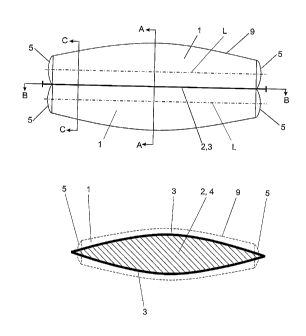
Figure 1 shows the pneumatic structural element according
to the invention in a first exemplary embodiment in plan
CA 02634505 2008-06-20
- 4 -
view. It is formed from two elongated, for example, cigar-
shaped gas-tight hollow bodies 1 comprising a casing 9 and
respectively two end caps 5, the hollow bodies 1 each
having a straight centre line L. Other forms of hollow
bodies 1 are included in the description to Fig. 12.
The casing 9 in each case consists, for example, of a
textile-laminated plastic film or of flexible plastic-
coated fabric. These hollow bodies 1 intersect one another,
abstractly geometrically, in a sectional area 2 as can be
seen from Fig. 2, which forms a section BE through Fig. 1.
When the two hollow bodies 1 are filled with compressed
gas, they acquire the form shown in section AA of Fig. 4,
under the conditions described hereinafter. As a result of
the pressure p in the interior of the hollow body 1, a
linear stress o is built up in its casings 9, which is
given by
o = p = R
o = linear stress [N/m]
p = pressure [N/m2]
R = radius of the hollow body 1 [m]
A textile web 4, for example, is inserted in the lines of
intersection of the two hollow bodies 1, in the sectional
area 2, to which the linear stresses o of the two hollow
bodies 1 are transmitted in the line of intersection, as
shown in Fig. 3. The tensile strength of the web 4 is
essential. Taking into account this fact, other materials,
preferably in the form of films, are naturally also
according to the invention.
A substantially the same configuration as in Figs. 1 and 2
can naturally be considered as a single hollow body which
is longitudinally constricted by the two interconnected
tension/compression elements 3 or the web 4, so that the
CA 02634505 2008-06-20
- 5 -
same linear stress relationships occur, as described for
Figs. 1 to 3. Figure 4 informally allows these two modes of
observation. However, the two end caps 5 then go over into
a single end cap 5.
Figure 3 shows the vectorial addition of the linear
stresses o to the linear force f in the web 4:
f = +
where
f = linear force in the web 4
= linear stress in the left hollow body
= linear stress in the right hollow body
For the same pressure p and the same radius R, the absolute
magnitude of f is dependent on the angle of intersection
of the two circles of intersection of the two hollow bodies
1.
In order to absorb tensile and compressive forces of the
pneumatic structural element thus constructed, the web 4 is
clamped into a tension/compression element 3 having the
form shown in Fig. 2. The tension/compression element 3
absorbs the part of this linear force determined by the
vector addition, as shown above, and is thereby pre-
tensioned in the direction given by the vector
representation. By filling the hollow body 1 with
compressed air, a pre-tensioning of the web 4 by the linear
force f is obtained as f = 2 a sin T. The linear force f
thus describes the resultant of the forces exerted by the
casing on the web, which is designated by o in Figure 3.
Since the radius along the structural element is not
generally constant, the pre-tensioning of the web along the
structural element varies. By a suitable choice of the
casing circumference and web height, the pre-tensioning of
CA 02634505 2008-06-20
- 6 -
the web can be optimised according to the use of the
pneumatic structural element or even made constant.
This pre-tensioning brings about a behaviour of the
tension/compression element 3 similar to a pre-tensioned
string which only responds with a change in length when the
pre-tensioning force is exceeded. Only when this pre-
tensioning force is exceeded is there a risk of the
tension/compression element 3 being bent. As a result of
the indicated type of elastic bedding of the
tension/compression element 3, in the pneumatic structural
element according to the invention, the spring constant k,
unlike that known from D2, is determined by the elasticity
of the web
k = E
where
E = modulus of elasticity of web [N/m2].
The modulus of elasticity of the web is determined by the
material. For textile webs the modulus of elasticity is in
the range of 108/ N/m2. A typical value for the internal
pressure p is 104 N/m2 (100 mbar). By incorporating the
web, the spring hardness has thus been increased by orders
of magnitude and accordingly also the bending load.
In the pneumatic structural element according to the
invention, therefore, the compressed air is used for pre-
tensioning the flexible web so that this can transmit
tensile and compressive forces and optimally stabilise the
compression member against bending. The pneumatic
structural element thus becomes more stable and light and
is better able to bear local loads. Furthermore, complex
three-dimensional pneumatic structural elements such as a
wing, for example, can be implemented with the =webs 4 and
by combining with the tension/compression elements 3, these
have a substantially greater load-bearing capacity than
conventional pneumatic structures.
CA 02634505 2008-06-20
- 7 -
The tension/compression element 3 is laterally stabilised
by the linear stresses o in the casing 9.
The web 4 running through the structural element forms,
together with the tension/compression elements 3, a braced
support for a load acting on the support in each case,
_
directed towards the bracing. The web 4 with the
tension/compression elements 3 can also be interpreted as a
truss as follows.
If, during operation, a load 'is acting on one of the
tension/compression elements 3, for example, on the
tension/compression element configured as a compressively
loadable stiffening element 30 as a result of the loading
direction (arrow 40), see figure 2b, the element 30 fulfils
the function of an upper chord of the truss 50 and the
tension/compression element configured as a tensile-
loadable element 33 fulfils the function of a lower chord.
The truss 50 thus consists of web 4, compressively loadable
stiffening element 30 and tensile-loadable stiffening
element 33.
The load symbolised by the arrow 40 is usually a load
distributed over the length of the element 30. In the case
of a likewise possible local load, the element 30 must be
correspondingly configured as rigid to prevent local
bending.
As mentioned, the web 4 is pre-tensioned by the internal
pressure prevailing in the structural element by a force
corresponding to the linear force f . Under load, the
compressively loadable stiffening element 30 is displaced
in the direction of action of the load 40. If in the case
of a distributed load, the latter remains below the linear
force f , the displacement is small (and takes place in
accordance with the modulus of elasticity of the still pre-_
CA 02634505 2008-06-20
- 8 -
tensioned web 4). However, if the linear force f exceeds
this, the displacement is greater with the risk that the
truss 50 will be overstressed.
The deformation under a load below the linear force f is
thus smaller than is the case in the pneumatic elements of
the prior art. If the operating load does not exceed the
linear load f , to a first approximation there is no
deformation of the structural element according to the
invention even when the load is non-constant.
If the compressively loadable stiffening element 30 and the
tensile-loadable connecting element 33 are formed in the
same manner, for example, as supports as shown in Figures 4
to 8, the truss 50 exhibits symmetry with the result that
when a load 44 is acting, the same relationships prevail:
the stiffening element 33 is compressively loadable and
acts as an upper chord of the truss 50; the stiffening
element 30 is tensile-loadable and acts as its lower chord.
Loading capacity is therefore provided from both sides
(load 40 and load 44).
In another embodiment according to the invention, the
tensile-loadable stiffening element 33 is exclusively
configured as tensile-loadable, for example, as a flexible
tension member such as is represented by a cable. Then, the
load-bearing capacity of the truss 50 is only unilateral,
given here by the load 40. The pre-determined spacing of
the stiffening elements 30, 33 (tension/compression members
3) is ensured by the internal pressure 9 which pre-tensions
the flexible web 4 by means of the linear force f
operationally, for exaMple, in the manner shown in Figure
4. This embodiment is characterised by low weight and, as
mentioned, is suitable for unilateral load (load 40).
CA 02634505 2008-06-20
- 9 -
According to the invention, the web 4 and the elements
arranged thereon (tension/compression members 3 or
compressively loadable stiffening element 30 and tensile-
loadable stiffening element 33 in the embodiment of Figure
2b) are operatively connected to the casing 9, i.e. are
connected in such a manner that forces can be transmitted
and the compressively loadable stiffening element in the
manner of an upper chord can absorb the corresponding
(i.e., acting in the direction of the lower chord) load
acting on the structural element. It is thus not important
whether the load (40, 44) acting on the stiffening element
30, 33 acts directly on the element 30, 33 or is introduced
via the casing 9 (Figure 4) into the element 30, 33. The
latter would be feasible if a roof according to Figure 13
bears a snow load or in the case of an aerofoil according
to Figures 10 and 11. It is also feasible that the load
acts directly on the web 4 and is introduced via said web
into the element 30, 33 which is likewise understood as a
load acting directly on the element 30, 33 for the purpose
of the description of the invention.
If the load 40 exceeds the linear load f , the truss 50
becomes deformed accordingly but continues to bear the load
40, 44 until either the compressively loadable element 30
bends or is destroyed as result of the compressive stresses
or the tensile-loadable element 33 tears. In this case, it
is naturally required that the elements 30, 33 retain their
relative position with respect to one another which is
crucial for the bearing properties of the truss 50. This
relative position is ensured by the pretension prevailing
in the web 4 as a result of the linear force f . Thus, in
addition to the afore-mentioned mechanical load-bearing
capacity of the elements 30,33, the permissible deformation
of the truss 50 is obtained as a second boundary condition
for the maximum load 40, this being given as long as the
pre-tensioning of the web 4 as such still exists. The
latter is dependent on the internal pressure p.
CA 02634505 2008-06-20
- 10 -
According to the invention, exceptional loading properties
of the pneumatic structural element are obtained together
with the advantages of a pneumatic structural element whose
elements 30, 33 are of comparatively low weight and the
smallest possible mass. In addition, said element has the
properties (load absorption, mass) of an optimised
conventional truss without considerable expenditure
(design, production and costs) needing to be incurred to
optimise the conventional truss.
Another preferred exemplary embodiment of the structural
element according to the invention is shown in Figure 2c.
The figure shows a pneumatic structural element 100 formed
by a web 110 to give two cylindrical sections 101 and 102
in the manner of a double cylinder. The casing 103
(consisting of a flexible gas-tight material) is connected
to a compressively loadable element configured as a
straight, compressively loadable support 104 and is
operationally connected via this to the web 110 in the
manner shown in Figures 4 to 7. Along its other
longitudinal side 111, the web 110 is connected to the
casing 103, for example, by welding or by gastight sewing.
The internal pressure p braces the web 110 made of flexible
material to give the flat rectangular form shown.
A tensile-loadable flexible tension member runs in the web
110, for example, a wire cable 113 that is fixed by means
of connections 114 in a fixed position on the web 110 in an
operational position. A truss 120 is thus obtained, this
being formed from the cable 113, the support 104 and the
web 110 which ensures the operational position of the truss
elements as a result of its pre-tension (linear force f).
The connections 114 can also be formed as tabs guided
through the web 110 or by any suitable technical method.
CA 02634505 2008-06-20
- 11 -
This arrangement makes it possible to configure the
external form of the casing independently of the
arrangement of the elements of the truss 120; there is no
need for the spindle-like shape according to Figures 1 and
2.
It is within the scope of the present invention to
configure both the web 110 and also the tensile-loadable
stiffening elements 113 as partially fixed and partially
flexible, which for example in the case of the tension
element 113 can be used for better fixing on the web 110 or
for other purposes.
Likewise, in addition to the form of a double cylinder,
another arbitrary configuration of the casing 103 can also
be provided within the scope of the design according to the
invention.
Figure 2d shows another embodiment of the structural
element according to the invention, wherein the parts shown
have the same reference numerals as in Figure 2c. The
support 104 is arranged downwardly offset in the web 110
and is no longer directly, but nevertheless operatively,
connected to the casing 103. In addition, the support 104
is arranged in a curved manner. The person skilled in the
art can freely determine the permissible curvature of the
support 104 depending on the application; the boundary
condition is that the support 104 remains in the
compression zone of the truss (support 104, web 110 and
tension element 113) over its entire length. The
supporting properties of this embodiment are the same as
those of the embodiment from Figure 2c.
Figure 4 shows a technical embodiment of the diagram
according to Fig. 3 in the section AA according to Fig. 1.
The tension/compression element 3 in this case, for
example, consists of two C profiles 8 which have been
CA 02634505 2008-06-20
- 12 -
screwed together. The casing 9 of the hollow body 1 is, for
example, pulled between the C profiles 8 without
interruption and is secured externally on the
tension/compression element 3 by means of a beading 10. The
web 4 is inserted between the external layers of the casing
9 and is clamped securely by the screw connection of the C
profiles 8.
Figure 5 shows a section through the tension/compression
element 3 thus executed in detail.
Figure 6 shows a variant for the design of the
tension/compression element 3 in cross-section. The
tension/compression element 3 here has three grooves for
beadings 10. The casings 9 of the two hollow bodies 1 are
inserted in the upper two grooves by means of beading 10
and the web 4 is inserted in the lower groove.
Figure 7 shows a cross-sectional view of another variant of
the tension/compression element with its fixing. Here, for
example, the tension/compression element 3 has a
rectangular cross-section but can also be differently
designed to optimise the areal moment of inertia. Said
element is inserted in a pocket 11 which is connected to
the casing 9 by welding or sewing and then sealing.
At their ends, the tension/compression elements 3 are
brought together in a node 14, as shown in Fig. 8. Such a
node can be designed in manifold ways and is known per se
in static calculations. Here this node consists of a plate
13 which is screwed, for example, to the
tension/compression elements 3. The air-tight termination
of the casing 9 can also be achieved in various ways. The
important thing here is that the tension/compression
elements 3 are guided out of the casing 9 and the node 14
lies freely for suitable fixing, for example, on a support.
CA 02634505 2008-06-20
- 13 -
Figure 9 shows the isometric projection of a pneumatic
structural element according to this invention. A plurality
of tension/compression elements 3 are provided here, one
web 4 being inserted in each case according to Fig. 2.
Respectively one hollow body 1 is clamped between two
neighbouring tension/compression elements 3 and filled with
compressed gas. The two outermost tension/compression
elements 3 are each adjoined by an unpaired hollow body 1
to produce the pre-tensioning of the tension/compression
element 3 and to laterally stabilise the
tension/compression elements 3. Such a surface structural
element can be constructed such that all the
tension/compression elements 3 and the casings 9 of the
hollow bodies 1 are already mounted and the entire
arrangement described is placed on supports 5 and then
filled with compressed gas. Alternatively assembly can take
place on site by fixing the tension/compression elements 3
on the supports and then joining the casings 9 to the
tension/compression elements 3.
In the diagram in Fig. 10 two groups of tension/compression
elements 3 are arranged in a crossed manner and form a two-
dimensional member 16 having a high bending strength in
two, for example perpendicular, axial directions. The
gastight terminations in the regions where the
tension/compression elements 3 cross one another can, for
example, be achieved by means of beadings; numerous other
solutions are naturally also possible here.
The advantage of a configuration as an actual two-
dimensional member 16 according to Fig. 10 is that the
individual tension/compression elements 3 are preferably
stabilised against tilting and no moments need to be
applied by a suitable support.
Figure 11, starting from Fig. 10, shows an aerofoil profile
17 according to the invention. As according to Fig. 10, two
CA 02634505 2008-06-20
- 14 -
groups of tension/compression elements 3 are arranged in a
crossed manner here. The numbers of tension/compression
elements 3 in the two groups, here two in one direction and
eight in the other direction, can be adapted to the
requirements for the aerofoil profile 17. Likewise, the
formation of the contours of the tension/compression
elements 3 is variable in the sense that in addition to the
static requirements on such a profile, the aerodynamic
shapes of leading and trailing edges 18, 19 can be suitably
configured, in any case using profile attachments which are
aerodynamically effective but are not part of the statics
of the aerofoil profile 17 with regard to its properties as
a two-dimensional member.
In the exemplary embodiment according to Fig. 12, the
centre lines L of the hollow body 1 are not straight as in
the exemplary embodiments according to Fig. 1 but are
outwardly curved from the interface 2 of the two hollow
bodies 1. The two hollow bodies 1, which intersect one
another in the sectional area 2 according to Fig. 2 and
which remain unchanged in their shape, therefore have the
smallest diameter in the cross-section AA according to Fig.
1. At the ends of the hollow body 1, this increases
however. Thus, the linear stress o proportional to the
local radius R also increases. Thus, the linear force
transmitted to the web 4 can be increased or, generally
speaking, optimised. Instead of a local radius increasing
towards the ends of the hollow body 1, it is naturally also
possible to select a constant or decreasing radius. In the
latter case, the linear stress decreases towards the ends
of the hollow body 1 and therefore of the web 4. This can
be achieved by a centre line L which is bent towards the
ends of the hollow body 1 towards the interface 2. The same
applies to hollow bodies 1 having approximately constant
radius, i.e. of toroidal shape.
CA 02634505 2008-06-20
- 15 -
Figure 13 shows another exemplary embodiment of the
inventive idea. Here a plurality, in Fig. 13 for example,
five, of hollow bodies 1 are arranged on a further smaller
plurality of tension/compression elements 3. These in turn
bear webs 4 and are guided out from the hollow bodies 1 in
a gas-tight manner. The tension/compression elements can be
differently selected both according to their length, their
height and also their direction. In each case as described
for Fig. 9, respectively one hollow body 1 is then joined
to the two outermost tension/compression elements 3 and
fixed thereon in order to symmetrise the linear stresses in
the said two outermost tension/compression elements 3 and
their webs 4 and to laterally stabilise said elements.