Language selection

Search

Patent 2634557 Summary

Third-party information liability

Some of the information on this Web page has been provided by external sources. The Government of Canada is not responsible for the accuracy, reliability or currency of the information supplied by external sources. Users wishing to rely upon this information should consult directly with the source of the information. Content provided by external sources is not subject to official languages, privacy and accessibility requirements.

Claims and Abstract availability

Any discrepancies in the text and image of the Claims and Abstract are due to differing posting times. Text of the Claims and Abstract are posted:

  • At the time the application is open to public inspection;
  • At the time of issue of the patent (grant).
(12) Patent: (11) CA 2634557
(54) English Title: SUCKER ROD
(54) French Title: TIGE DE POMPAGE
Status: Granted
Bibliographic Data
(51) International Patent Classification (IPC):
  • E21B 17/042 (2006.01)
(72) Inventors :
  • PLISKA, ROSS (Canada)
(73) Owners :
  • DOVER CORPORATION (CANADA) LIMITED (Canada)
(71) Applicants :
  • DOVER CORPORATION (CANADA) LIMITED (Canada)
(74) Agent: WOODRUFF, NATHAN V.
(74) Associate agent:
(45) Issued: 2013-06-11
(22) Filed Date: 2008-05-07
(41) Open to Public Inspection: 2009-11-07
Examination requested: 2011-02-15
Availability of licence: N/A
(25) Language of filing: English

Patent Cooperation Treaty (PCT): No

(30) Application Priority Data: None

Abstracts

English Abstract

An improvement in a sucker rod having an elongated metal body with opposed ends and threaded couplings positioned at each of the opposed ends comprises a thread form on the threaded couplings defining at least two concurrent helixes. Each of the at least two helixes has a different starting position on a circumference of the threaded coupling.


French Abstract

Une amélioration d'une tige de pompage ayant un corps métallique allongé avec des extrémités opposées et des manchons filetés disposés au niveau de chacune des extrémités opposées comprend une forme de fil sur les manchons filetés définissant au moins deux hélices parallèles. Chacune des au moins deux hélices a une position de départ différente sur une circonférence du manchon fileté.

Claims

Note: Claims are shown in the official language in which they were submitted.

5
What is Claimed is:
1. A sucker rod string connected to a rotary pump positioned in a well,
comprising:
a plurality of sucker rods connected end to end, each sucker rod comprising:
an elongated metal body with opposed ends and threaded couplings and pin
shoulders positioned at at least one of the opposed ends; and
a thread form on the threaded couplings of the sucker rod defining at least
two
concurrent helixes, each of the at least two helixes having a different
starting position on a
circumference of the threaded coupling, such that, when torque is applied to
the sucker rod
string to drive the rotary pump, the thread form reduces the risk of damage to
the threaded
coupling.

2. The sucker rod string of Claim 1, wherein the threaded couplings are male
threaded
couplings.

3. A sucker rod string connected to a rotary pump positioned down a well, the
sucker rod
string comprising:
a plurality of sucker rods connected end to end, each sucker rod comprising:
an elongated metal body having opposed first and second ends,
a leading end of each of the first and the second ends of the sucker rod
having
a threaded coupling, and
a shoulder being located closely adjacent the threaded coupling and separating

the threaded coupling from a remainder of the sucker rod,
the improvement wherein a thread form on the threaded coupling of the sucker
rod define at least two concurrent helixes, and each of the at least two
helixes have a different
starting position on a circumference of the threaded coupling, such that, when
torque is
applied to the sucker rod string to drive the rotary pump, the thread form
reduces the risk of
damage to the threaded coupling.

Description

Note: Descriptions are shown in the official language in which they were submitted.


CA 02634557 2008-05-07
1
TITLE:
Sucker rod
FIELD
The present invention relates to a sucker rod which forms part of a rod string
connecting surface equipment with a pump positioned down a well.

BACKGROUND
A sucker rod has an elongated metal body with threaded couplings at each end.
The
sucker rods are connected end to end to form a rod string to operate a pump
positioned down
a well. When there is a failure in the rod string, it can usually be
attributed a failure occurring
at one of the threaded couplings. In order to avoid such failures, the
threaded couplings are
being made considerably stronger than the body of the sucker rods.
Notwithstanding that the
threaded couplings are stronger, failures of the rod string are still
occurring at the threaded
coupling.

SUMMARY
There is provided an improvement in a sucker rod having an elongated metal
body
with opposed ends and threaded couplings positioned at each of the opposed
ends. The
improvement includes a thread form on the threaded couplings defining at least
two
concurrent helixes. Each of the helixes has a different starting position on a
circumference of
the threaded coupling.

It is believed that premature failure of rod strings at threaded couplings
between the
sucker rod sections that make up the rod string can be attributed to human
error. If a threaded
coupling is not made up correctly, reactive torque acting upon the rod string
can result in
substantial torque being applied to the rod string.

BRIEF DESCRIPTION OF THE DRAWINGS
3 These and other features will become more apparent from the following
description in
which reference is made to the appended drawings, the drawings are for the
purpose of
illustration only and are not intended to in any way limit the scope of the
invention to the


CA 02634557 2008-05-07
2

particular embodiment or embodiments shown, wherein:
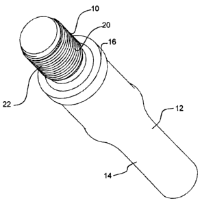
FIG. 1 is a perspective view of an improved sucker rod.
FIG. 2 is an end elevation view of an improved sucker rod.
FIG. 3 is a side elevation view of an improved sucker rod.
FIG. 4 is a diagram depicting the axial load generated when a torque is
exerted on the
connection.

DETAILED DESCRIPTION
A thread form 10 for a sucker rod 12 will now be described with reference to
FIG. 1
through 4.

Structure and Relationship of Parts:
Referring to FIG. 1, sucker rod 12 has an elongated metal body 14 with opposed
ends
16 (only one end 16 being shown), and threaded couplings 20 positioned at each
opposed end.
Thread form 10 is positioned on threaded couplings 20, such as male threaded
couplings as
shown, female threaded couplings (not shown), or a male threaded coupling at
one end and a
female threaded coupling at the other. Thread form 10 defines two concurrent
helixes 22. As
shown in FIG. 2, each helix 22 has a different starting position on a
circumference of the
threaded coupling 20. While two helixes 22 have been illustrated, it will be
apparent that
more than two helixes 22 may be used.

When installed, thread form 10 as shown is used to mate with a corresponding
female
thread form (not shown) with a similar double helix design.

Advantages:
By designing couplings 20 to have two or more helixes results in a multiple-
start
threaded connection, better results are provided in instances where a slip
event is prone to
occur. A slip event generally occurs when the frictional forces induced during
the connection
makeup are not string enough to hold under operational torque. This is mainly
due to
improper makeup torque, or the presence of lubricant in connection mating
surfaces. Due to
its larger lead angle (the pitch of the thread as it winds about the
connection) relative to a
single start threaded connection, the multiple start thread connection
generates less axial loads


CA 02634557 2008-05-07
3

when subjected to the same torque. Given that both threads are transferring
the same torque,
the axial load on the multiple start thread is less than the axial load on the
single start thread.
For this reason, the multiple start thread has fewer tendencies to become
damaged at higher
torque rates, either during a slip event or otherwise. For example, in one
test that was
performed, it was found that, with consistent, improper makeup techniques,
traditional single
start connections failed in the connection about half the time, whereas the
multiple start
connection never failed in the connection. Furthermore, the larger lead angle
also allows the
multiple start threaded connection to be made up faster than the single start
threaded
connection.
Referring to FIG. 4, the advantages offered by the multiple start thread
principle are
illustrated by considering the equation for the component of torque that is
used to develop the
axial load. In the discussion below, the following nomenclature is used:
T = Torque
Ts = Torque on single start threaded connection
T= Torque on multiple start threaded connection
P = Axial load
P~, = Axial load on the single start threaded connection
P,n = Axial load on the multiple start threaded connection
L = Lead
L.S = Lead of the single start threaded connection
Lõ, = Lead of the multiple start threaded connection
The equation that defines the torque component is:
T PL
2;r ----------------Eq. 1
Adopt Eq. # 1 for multiple start thread:

Tm = Pm Lm
2z ------------Eq.2
Adapt Eq. # 1 for single start thread:


CA 02634557 2008-05-07
4
TS _ Pr Ls
21c --------------Eq.3

For comparison purposes the torque is equal for both types of thread:
T. = TS ------------------ Eq. 4
Substitute Eq.2 and Eq.3 into Eq. 4 and solve for P,,,:
P.L. P, Ls.
21r 21c
Pm = PSLS
L,,,
--------------Eq.S
Given that the multiple thread coupling has a larger lead than the single
thread
coupling, then:
Lm> L.S. -------------------Eq.6

The condition in Eq.6 is inserted it into Eq.5 to find which axial load is
greater.
.: Pm< P.c

In this patent document, the word "comprising" is used in its non-limiting
sense to
mean that items following the word are included, but items not specifically
mentioned are not
excluded. A reference to an element by the indefinite article "a" does not
exclude the
possibility that more than one of the element is present, unless the context
clearly requires that
there be one and only one of the elements.

It will be apparent to one skilled in the art that modifications may be made
to the
illustrated embodiments without departing from scope of the Claims.

Representative Drawing
A single figure which represents the drawing illustrating the invention.
Administrative Status

For a clearer understanding of the status of the application/patent presented on this page, the site Disclaimer , as well as the definitions for Patent , Administrative Status , Maintenance Fee  and Payment History  should be consulted.

Administrative Status

Title Date
Forecasted Issue Date 2013-06-11
(22) Filed 2008-05-07
(41) Open to Public Inspection 2009-11-07
Examination Requested 2011-02-15
(45) Issued 2013-06-11

Abandonment History

There is no abandonment history.

Maintenance Fee

Last Payment of $624.00 was received on 2024-03-12


 Upcoming maintenance fee amounts

Description Date Amount
Next Payment if standard fee 2025-05-07 $624.00
Next Payment if small entity fee 2025-05-07 $253.00

Note : If the full payment has not been received on or before the date indicated, a further fee may be required which may be one of the following

  • the reinstatement fee;
  • the late payment fee; or
  • additional fee to reverse deemed expiry.

Patent fees are adjusted on the 1st of January every year. The amounts above are the current amounts if received by December 31 of the current year.
Please refer to the CIPO Patent Fees web page to see all current fee amounts.

Payment History

Fee Type Anniversary Year Due Date Amount Paid Paid Date
Application Fee $400.00 2008-05-07
Registration of a document - section 124 $100.00 2008-10-15
Maintenance Fee - Application - New Act 2 2010-05-07 $100.00 2010-03-16
Request for Examination $800.00 2011-02-15
Maintenance Fee - Application - New Act 3 2011-05-09 $100.00 2011-02-15
Maintenance Fee - Application - New Act 4 2012-05-07 $100.00 2012-04-11
Maintenance Fee - Application - New Act 5 2013-05-07 $200.00 2013-03-01
Final Fee $300.00 2013-04-03
Maintenance Fee - Patent - New Act 6 2014-05-07 $200.00 2014-02-10
Maintenance Fee - Patent - New Act 7 2015-05-07 $200.00 2015-02-19
Maintenance Fee - Patent - New Act 8 2016-05-09 $200.00 2016-02-17
Maintenance Fee - Patent - New Act 9 2017-05-08 $200.00 2017-02-13
Maintenance Fee - Patent - New Act 10 2018-05-07 $250.00 2018-05-01
Maintenance Fee - Patent - New Act 11 2019-05-07 $250.00 2019-03-26
Maintenance Fee - Patent - New Act 12 2020-05-07 $250.00 2020-04-01
Maintenance Fee - Patent - New Act 13 2021-05-07 $255.00 2021-04-27
Maintenance Fee - Patent - New Act 14 2022-05-09 $254.49 2022-05-04
Maintenance Fee - Patent - New Act 15 2023-05-08 $473.65 2023-02-27
Maintenance Fee - Patent - New Act 16 2024-05-07 $624.00 2024-03-12
Owners on Record

Note: Records showing the ownership history in alphabetical order.

Current Owners on Record
DOVER CORPORATION (CANADA) LIMITED
Past Owners on Record
PLISKA, ROSS
Past Owners that do not appear in the "Owners on Record" listing will appear in other documentation within the application.
Documents

To view selected files, please enter reCAPTCHA code :


To view images, click a link in the Document Description column. To download the documents, select one or more checkboxes in the first column and then click the "Download Selected in PDF format (Zip Archive)" or the "Download Selected as Single PDF" button.

List of published and non-published patent-specific documents on the CPD .

If you have any difficulty accessing content, you can call the Client Service Centre at 1-866-997-1936 or send them an e-mail at CIPO Client Service Centre.


Document
Description 
Date
(yyyy-mm-dd) 
Number of pages   Size of Image (KB) 
Abstract 2008-05-07 1 9
Description 2008-05-07 4 128
Claims 2008-05-07 1 11
Drawings 2008-05-07 3 29
Maintenance Fee Payment 2023-02-27 1 33
Cover Page 2009-10-27 1 29
Representative Drawing 2009-10-15 1 7
Claims 2012-11-06 1 36
Cover Page 2013-05-27 1 30
Fees 2010-03-16 1 27
Assignment 2008-05-07 2 70
Correspondence 2008-07-25 2 75
Assignment 2008-10-15 2 87
Correspondence 2010-01-11 1 38
Correspondence 2008-12-05 1 21
Correspondence 2011-03-31 3 155
Correspondence 2011-02-16 1 78
Fees 2011-02-15 1 28
Prosecution-Amendment 2011-02-15 1 28
Prosecution-Amendment 2011-02-15 1 29
Correspondence 2011-05-16 1 20
Correspondence 2011-05-16 1 35
Prosecution-Amendment 2012-09-11 2 55
Prosecution-Amendment 2012-11-06 7 210
Correspondence 2013-04-03 1 36
Fees 2016-02-17 1 33