Note: Descriptions are shown in the official language in which they were submitted.
CA 02634594 2008-06-20
WO 2007/076083 PCT/US2006/049159
1
DRY MATRICES AS DRUG RESERVOIRS IN ELECTROTRANSPORT
APPLICATIONS
CROSS REFERENCE TO RELATED APPLICATIONS
[0001] This application claims the benefit of U.S. application serial number
11/613,327, filed December 20, 2006 and U.S. application serial number
60/753,359, filed
December 22, 2005, each of which is incorporated herein by reference in its
entirety.
FIELD OF THE INVENTION
[0002] The present invention relates to devices and methods for the
electrotransport
delivery of beneficial agents that utilize polymer electrolyte reservoirs. In
certain aspects of the
invention, the beneficial agents are hydrolytically unstable, but remain
stable during storage of
the electrotransport devices and during electrotransport delivery.
BACKGROUND OF THE INVENTION
[0003] The transdermal delivery of therapeutic agents by diffusion through the
epidermis offers certain improvements over more traditional drug delivery
methods, such as
subcutaneous injection and oral delivery. Transdermal drug delivery avoids the
hepatic first pass
effect encountered with oral drug delivery, and also eliminates patient
discomfort associated with
subcutaneous injections. In addition, transdermal delivery can provide more
uniform
concentrations of a drug in the bloodstream of the patient over time due to
the extended
CA 02634594 2008-06-20
WO 2007/076083 PCT/US2006/049159
2
controlled delivery profiles of certain types of transdermal delivery devices.
[0004] The skin functions as the primary barrier to the transdermal
penetration of
materials into the body and represents the body's major resistance to the
transdermal delivery of
therapeutic agents such as drugs. To date, efforts have focused on reducing
the physical
resistance or enhancing the permeability of the skin for the delivery of drugs
by passive
diffusion. Various methods for increasing the rate of transdermal drug flux
have been attempted,
most notably using chemical flux enhancers. Other approaches for increasing
the rate of
transdermal drug delivery include the use of energy sources, such as
electrical energy and
ultrasonic energy, to electrically assist the transdermal delivery of
therapeutic agents.
[0005] Hydrophillic polymer-based gels, or hydrogels, are commonly used as
drug
reservoirs in electrotransport drug delivery devices. Hydrogels typically
contain approximately
80 % water in their final, processed form that contains the therapeutic agent,
and the water
provides a conduction medium and pathway for the transport of the agent via
electrotransport.
Hydrogels are therefore excellent biocompatible reservoirs for therapeutic
agents that have
sufficient aqueous stability. Chemical stability problems can arise, however,
when
hydrolytically unstable therapeutic agents are fonnulated in hydrogels for
electrotransport
delivery. Such stability problems can arise both during electrotransport
delivery and during
long-term storage of the delivery devices. Furthermore, in electrotransport
devices in which the
electronics and the therapeutic agent formulation are assembled in a single
compartment, the
electronics can be negatively affected by the moisture and relative humidity
associated with
hydrogels. There is thus a need in the art for drug reservoirs for
electrotransport drug delivery
devices that can be used with hydrolytically unstable therapeutic agents and
that do not
negatively affect the electronic components of the devices.
SUMMARY OF THE INVENTION
[0006] Certain aspects of the present invention relate to devices for the
electrotransport
delivery of beneficial agents that comprise a donor electrode assembly
comprising a donor
reservoir that comprises a substantially solvent-free polymer electrolyte, a
counter electrode
assembly, and a source of electrical power connected to the donor and counter
electrode
assemblies. In preferred embodiments of the invention, the polymer electrolyte
is substantially
free of oxidants and ionic impurities and contains a beneficial agent that
remains stable during
long-term storage of the device and during electrotransport.
CA 02634594 2008-06-20
WO 2007/076083 PCT/US2006/049159
3
[0007] Other aspects of the present invention relate to methods for enhancing
the
stability of hydrolytically unstable beneficial agents during long-term
storage of devices for the
electrotransport delivery of hydrolytically unstable beneficial agents and
during electrotransport
delivery of hydrolytically unstable beneficial agents. Such methods preferably
comprise
providing a device for the electrotransport delivery of hydrolytically
unstable beneficial agents
that comprises a donor electrode assembly comprising a donor reservoir that
comprises a
polymer electrolyte matrix that is substantially free of oxidants and ionic
impurities and contains
the hydrolytically unstable beneficial agent; a counter electrode assembly;
and a source of
,electrical power adapted to be electrically connected to the donor and
counter electrode
assemblies. In preferred aspects, such methods further comprise storing the
devices for up to six
months; and administering the hydrolytically unstable beneficial agent to a
patient using the
device, wherein the hydrolytically unstable beneficia.l agent remains stable
during storage and
during electrotransport.
BRIEF DESCRIPTION OF THE DRAWINGS
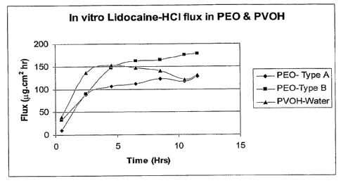
[0008] Figure 1 depicts the in vitro flux of lidocaine HCl in various
matrices.
[0009] Figure 2 is an HPLC chromatogram that demonstrates improved stability
of
hydrolytically labile hydrocortisone hemisuccinate (HCHS) in polyethylene
oxide (PEO)
matrices as compared to polyvinyl alcohol (PVOH) hydrogels.
[0010] Figure 3A shows the results of stability studies of HCHS in PVOH
hydrogels.
[0011] Figure 3B shows the results of stability=studies of HCHS in PEO films.
[0012] Figure 4 shows the stability of apomorphine in various PEO matrices.
PEO20-
200K: the molecular weight (MW) of PEO used was 200K and the ratio of PEO to
drug was 20;
PEO10-7000K: the MW of PEO used was 7000K and the ratio of PEO to drug was 10;
PE020-
7000K: the MW of PEO used was 7000K and the ratio of PEO to drug was 20.
[0013] Figure 5A shows a comparison of apomorphine in vitro transdermal
electrotransport flux in PVOH and PEO matrices as a function of time showing
the rise to steady
state and the steady state profile. I
[0014] Figure 5B shows the steady state average flux values for the in vitro
transdermal
electrotransport flux of apomorphine in PVOH and PEO matrices.
[0015] Figure 6 shows the in vitro flux of fentanyl HCl ( g/cm2hr) in a PEO
matrix.
CA 02634594 2008-06-20
WO 2007/076083 PCT/US2006/049159
4
[0016] Figure 7 shows a comparison of the in vitro flux of fentanyl HCl in a
PEO
matrix with that of fentanyl HCl in a PVOH hydrogel. PVOH-Fentanyl R is a
repeat study.
[0017] Figure 8 is a perspective exploded view of an electrotransport drug
delivery
device in accordance with certain aspects of the present invention.
DETAILED DESCRIPTION OF ILLUSTRATIVE EMBODIMENTS
[0018] Certain aspects of the present invention relate to polymer electrolyte
matrices
that can be used as drug reservoirs in electrotransport drug delivery devices.
Polymer
electrolytes are solvent-free, ion-conducting polar polymers that can
transport charged molecules
and ions. Polymer electrolytes contain cation coordinating sites, such as
polar groups having
lone pair electrons, have a highly amorphous morphology, and have low glass
transition
temperatures leading to highly flexible polymer backbones.
[0019] The ionic conductivity and ion transport properties of polymer
electrolytes are
due to the large amplitude segmental motion of the polymers that occurs upon
electrical
perturbation. Polymer electrolytes include polyethylene oxide, whose ability
to act as an
electrolyte to transport cations has been studied in detail in connection with
electrochemical
devices such as batteries, gas sensors, and fuel cells. Substantially solvent-
free polymer
electrolyte matrices make ideal reservoirs for electrotransport devices used
for the delivery of
therapeutic agents that are hydrolytically unstable during long-term storage
and during
electrotransport. The use of dry polymer electrolyte reservoirs for
electrotransport devices also
eliminates problems, such as corrosion or electrical shorting, that can arise
when humidity from
hydrated reservoirs penetrates the electronic components of electrotransport
devices.
Furthermore, the use of dry polymer electrolyte reservoirs with low ohmic
resistance eliminates
the extra step of hydration that is required when hydratable donor matrices
are used. In addition,
polymer electrolyte matrices facilitate miniaturization of electrotransport
beneficial agent
delivery devices, particularly the beneficial agent reservoir.
[0020] Certain aspects of the present invention relate to dry, substantially
solvent-free
polymer electrolyte matrices for electrotransport drug delivery devices that
are in the form of
thin films.
[0021] As used herein, the terms "electrotransport," "iontophoresis," and
"iontophoretic" refer to the delivery of pharmaceutically active agents
(charged, uncharged, or
mixtures thereof) through a body surface (such as skin, mucous membrane, eye,
or nail) wherein
CA 02634594 2008-06-20
WO 2007/076083 PCT/US2006/049159
the delivery is at least partially induced or aided by the application of an
electric potential. The
agent may be delivered by electromigration, electroporation, electroosmosis or
any combination
thereof. Electromigration (also called iontophoresis) involves the
electrically induced transport
of charged ions through a body surface. Electroosmosis has also been referred
to as
electrohydrokinesis, electro-convection, and electrically induced osmosis. In
general,
electroosmosis of a species into a tissue results from the migration of
solvent in which the
species is contained, as a result of the application of electromotive force to
the therapeutic
species reservoir, i.e., solvent flow induced by electromigration of other
ionic species. During
the electrotransport process, certain modifications or alterations of the skin
may occur such as
the formation of transiently existing pores in the skin, also referred to as
"electroporation." Any
electrically assisted transport of species enhanced by modifications or
alterations to the body
surface (e.g., formation of pores in the skin) are also included in the term
"electrotransport" as
used herein. Thus, as used herein, the terms "electrotransport,"
"iontophoresis" and
"iontophoretic" refer to (1) the delivery of charged drugs or agents by
electromigration, (2) the
delivery of uncharged drugs or agents by the process of electroosmosis, (3)
the delivery of
charged or uncharged drugs by electroporation, (4) the delivery of charged
drugs or agents by the
combined processes of electromigration and electroosmosis, and/or (5) the
delivery of a mixture
of charged and uncharged drugs or agents by the combined processes of
electromigration and
electroosmosis.
[0022] In electrotransport devices, at least two electrodes are used. Both of
the
electrodes are disposed so as to be in intimate electrical contact with some
portion of the skin,
nails, mucous membrane, or other surface of the body. One electrode, called
the "active" or
"donor" electrode, is the electrode from which the drug is delivered into the
body. The other
electrode, called the "counter" or "return" electrode, serves to close the
electrical circuit through
the body. In conjunction with the patient's skin, the circuit is completed by
connection of the
electrodes to a source of electrical power, e.g., a battery, and usually to
circuitry capable of
controlling current passing through the device. If the ionic substance to be
driven into the body
is positively charged, then the positive electrode (the anode) will be the
donor electrode and the
negative electrode (the cathode) will serve as the counter electrode,
completing the circuit. If the
ionic substance to be delivered is negatively charged, then the cathodic
electrode will be the
donor electrode and the anodic electrode will be the counter electrode. Both
the anode and the
cathode can be donor electrodes if both anionic and cationic therapeutic agent
ions are to be
CA 02634594 2008-06-20
WO 2007/076083 PCT/US2006/049159
6
delivered, or if an uncharged therapeutic agent is to be delivered.
[0023] Electrotransport devices additionally require a reservoir or source of
the
pharmaceutically active agent that is to be delivered or introduced into the
body, referred to as
the "donor reservoir." Examples of donor reservoirs include a pouch or cavity,
a porous sponge
or pad, and a hydrophilic polymer or gel matrix. Such drug reservoirs are
connected to, and
positioned between, the donor electrode of the electrotransport device and the
body surface, to
provide a fixed or renewable source of one or more desired species or agents.
The term "donor
electrode assembly" thus refers to the donor electrode and the donor
reservoir. Similarly, the
term "counter electrode assembly" refers to the counter electrode and the
counter reservoir,
which contains one or more biocompatible electrolytes.
[0024] Electrotransport devices are powered by an electrical power source such
as one
or more batteries. Typically, at any one time, one pole of the power source is
electrically
connected to the donor electrode, while the opposite pole is electrically
connected to the counter
electrode. Since it has been shown that the rate of electrotransport drug
delivery is
approximately proportional to the electric current applied by the device, many
electrotransport
devices typically have an electrical controller that controls the voltage
and/or current applied
through the electrodes, thereby regulating the rate of drug delivery. These
control circuits use a
variety of electrical components to control the electrical signal, i.e., the
amplitude, polarity,
timing, waveform shape, etc. of the electric current and/or voltage, supplied
by the power
source. U.S. Patent No. 5,047, 007 to McNichols, et al., which is hereby
incorporated by
reference in its entirety, discloses several suitable parameters and
characteristics.
100251 An electrotransport device or system, with its donor and counter
electrodes, may
be thought of as an electrochemical cell having two electrodes, each electrode
having an
associated half cell reaction, between which electrical current flows.
Electrical current flowing
through the conductive (e.g., metal) portions of the circuit is carried by
electrons (electronic
conduction), while current flowing through the liquid-containing portions of
the device (i.e., the
drug reservoir in the donor electrode, the electrolyte reservoir in the
counter electrode, and the
patient's body) is carried by ions (ionic conduction). Current is transferred
from the metal
portions to the liquid phase by means of oxidation and reduction charge
transfer reactions that
typically occur at the interface between the metal portion (e.g., a metal
electrode) and the liquid
phase (e.g., the drug solution). A detailed description of the electrochemical
oxidation and
reduction charge transfer reactions of the type involved in electrically
assisted drug transport can
CA 02634594 2008-06-20
WO 2007/076083 PCT/US2006/049159
7
be found in electrochemistry texts such as J. S. Newman, Electrochemical
Systems (Prentice
Hall, 1973) and A. J. Bard and L. R. Faulkner, Electrochemical Methods,
Fundamentals and
Applications (John Wiley & Sons, 1980).
[0026] As used herein, the terms "transdermal administration" and
"transdermally
administering" refer to the delivery of a substance or agent by passage into
and through the skin,
nails, mucous membrane, or other surface of the body.
[0027] As used herein, the term "matrix" refers to a porous, composite, solid,
or semi-
solid substance, such as, for example, a polymeric material or a gel, that has
pores or spaces
sufficiently large for a beneficial agent to populate. The matrix serves as a
repository in which
the beneficial agent is contained.
[0028] As used herein, the phrase "substantially free of oxidants and
impurities" refers
to polymer electrolytes that contain no more than a trace or trivial amount of
oxidants and ionic
impurities.
[0029] As used herein, the phrase "long-term storage" refers to the storage of
an
electrotransport beneficial agent delivery device for a period of time that is
at least two weeks.
For example, storage of electrotransport delivery devices for periods of time
that would be
considered "long-term' include storage for at least one month, at least three
months, at least six
months, or at least twelve months.
[0030] As used herein, the term "beneficial agent" refers to any agent that
elicits a
desired beneficial; often pharmacological, effect upon administration to a
human or animal,
whether alone or in combination with other pharmaceutical excipients or inert
ingredients.
[0031] As used herein, the term "polymer electrolyte" refers to any polymeric
material
that is capable of conducting ions. Polymer electrolytes can be substantially
free of solvents, or
can contain trace amounts of the solvents that are used to cast films of the
polymer electrolytes.
[0032] As used herein, the term "hydrolytically unstable" refers to substances
that
undergo degradation by hydrolysis. The term "hydrolysis" refers to any
chemical process by
which a molecule is cleaved into two or more parts by the addition of water.
[0033] As used herein, the phrase "beneficial agent that remains stable"
refers to a
beneficial agent that remains substantially intact and does not undergo
hydrolysis to a significant
degree during long-term storage of an electrotransport delivery device
containing the beneficial
agent and during electrotransport delivery of the beneficial agent. The term
"stability," as used
herein, refers to the extent that a beneficial agent is resistant to
hydrolysis.
CA 02634594 2008-06-20
WO 2007/076083 PCT/US2006/049159
8
[0034] As used herein, the phrase ' method for enhancing the stability of a
hydrolytically unstable beneficial agent" refers to methods that result in any
measurable increase
in the stability of a hydrolytically unstable beneficial agent.
[0035] As used herein, the term "thin film" refers to polymer electrolyte
films that are
from approximately 0.2 mm to approximately 2.0 mm thick. In certain
embodiments of the
invention, layers of thin polymer electrolyte films can be used to obtain
polymer electrolyte films
that are approximately 1.59 mm thick.
J0036] Particular aspects of the present invention relate to devices for the
electrotransport delivery of beneficial agents. In preferred embodiments of
the invention, the
devices comprise a donor electrode assembly that comprises a donor reservoir
comprising a
polymer electrolyte that is substantially free of oxidants and impurities and
contains a beneficial
agent that remains stable during long-term storage of the device and during
electrotransport.
Preferably, the devices further comprise a counter electrode assembly and a
source of electrical
power connected to the donor and counter electrode assemblies.
[0037] Other aspects of the invention relate to methods for enhancing the
stability of
hydrolytically unstable beneficial agents during long-term storage of devices
for the
electrotransport delivery of hydrolytically unstable beneficial agents and
during electrotransport
delivery of hydrolytically unstable beneficial agents. In preferred
embodiments of the invention,
such methods comprise providing a device for the electrotransport delivery of
hydrolytically
unstable beneficial agents that comprises a donor electrode assembly. The
donor electrode
assembly preferably comprises a donor reservoir comprising a polymer
electrolyte that is
substantially free of oxidants and impurities and contains the hydrolytically
unstable beneficial-
agent. The device further preferably comprises a counter electrode assembly
and a source of
electrical power connected to the donor and counter electrode assemblies. The
methods further
preferably comprise storing the device for up to six months and administering
the hydrolytically
unstable beneficial agent to a patient using the device. In preferred aspects
of the invention, the
hydrolytically unstable beneficial agent remains stable during storage and
during
electrotransport.
[0038] In certain aspects of the methods of the invention, a device for the
electrotransport delivery of a hydrolytically unstable beneficial agent is
stored for up to six
months prior to the electrotransport delivery of the hydrolytically unstable
beneficial agent, and
the beneficial agent remains stable throughout the time in which it is stored
in the
CA 02634594 2008-06-20
WO 2007/076083 PCT/US2006/049159
9
electrotransport delivery device. In other aspects of the invention, a device
for the
electrotransport delivery of a hydrolytically unstable beneficial agent is
stored for any period of
time of at least six months, and the beneficial agent remains stable
throughout the period of time
in which it is stored in the electrotransport delivery device.
[00391 In preferred embodiments of the devices and methods of the present
invention,
the beneficial agent delivered via electrotransport has a net positive or
negative charge. In other
embodiments of the invention, the beneficial agent is hydrolytically unstable
and undergoes
hydrolysis or structural degradation upon exposure to water. In certain
aspects of the invention,
the hydrolytically unstable beneficial agent is a hydrolytically unstable
protein or polypeptide.
[00401 Particular embodiments of the invention relate to electrotransport
devices and
methods in which the beneficial agent delivered via electrotransport is
lidocaine hydrochloride,
hydrocortisone hemisuccinate, apomorphine hydrochloride, or fentanyl
hydrochloride. In other
embodiments of the invention, the beneficial agent is leutinizing hormone
releasing hormone
(LHRH), an LHRH analog (such as goserelin, leuprolide, buserelin, triptorelin,
gonadorelin, and
napfarelin, a menotropin (urofollitropin (FSH) and LH)), vasopressin,
desmopressin,
corticotrophin (ACTH), an ACTH analog such as ACTH (1-24), calcitonin,
vasopressin,
deamino[Va14, I)-Arg8] arginine vasopressin, interferon alpha, interferon
beta, interferon
gamma, erythropoietin (EPO), granulocyte macrophage colony stimulating factor
(GM-CSF),
granulocyte colony stimulating factor (G-CSF), interleukin-10 (IL-10),
glucagon, growth
horrnone releasing factor (GHRF), insulin, insulinotropin; calcitonin,
octreotide, endorphin,
TRN, NT-36 (chemical name: N[[(s)-4-oxo-2-azetidinyl]carbonyl]-L- histidyl-L-
prolinamide),
liprecin, aANF, bMSH, somatostatin, bradykinin, somatotropin, platelet-derived
growth factor
releasing factor, chymopapain, cholecystokinin, chorionic gonadotropin,
epoprostenol (platelet
aggregation inhibitor), glucagon, hirulog, an interferon, an interleukin, a
menotropin
(urofollitropin (FSH) and LH), oxytocin, streptokinase, tissue plasminogen
activator, urokiriase,
ANP, ANP a clearance inhibitor, BNP, VEGF, an angiotensin II antagonist, an
antidiuretic
hormone agonist, a bradykinin antagonist, ceredase, a CSI, calcitonin gene
related peptide
(CGRP), an enkephalin, a FAB fragment, IgE a peptide suppressor, IGF-1, a
neurotrophic factor,
a colony stiniulating factor, a parathyroid hormone and agonist, a parathyroid
hormone
antagonist, a prostaglandin antagonist, pentigetide, protein C, protein S, a
renin inhibitor,
thymosin alpha-l, a thrombolytic, TNF, a vasopressin antagonist analog, alpha-
i antitrypsin
(recombinant), TGF-beta, fondaparinux, ardeparin, dalteparin, defibrotide,
enoxaparin, hirudin,
CA 02634594 2008-06-20
WO 2007/076083 PCT/US2006/049159
nadroparin, reviparin, tinzaparin, pentosan polysulfate, an oligonucleotides
and oligonucleotide
derivative such as formivirsen, alendronic acid, clodronic acid, etidronic
acid, ibandronic acid,
incadronic acid, pamidronic acid, risedronic acid, tiludronic acid, zoledronic
acid, argatroban,
RWJ 445167, RWJ-671818, fentanyl, remifentanil, sufentanil, alfentanil,
lofentanil, carfentanil,
and mixtures thereof.
[0041] In particular aspects of the present invention, the electrotransport
beneficial
agent delivery devices comprise a donor electrode assembly that comprises a
donor reservoir
comprising a polymer electrolyte. The polymer electrolyte is substantially
free of oxidants and
impurities. In particular embodiments, polymer electrolytes that contain
antioxidants are
preferred.
[0042] In certain embodiments of the invention, the polymer electrolyte that
comprises
the donor reservoir of an electrotransport beneficial agent delivery device is
in the form of a thin
film, and the polymer electrolyte is preferably polyethylene oxide, a
polysiloxane having a
hydrophilic side chain, or a polyphosphazene having a hydrophilic side chain.
In particularly
preferred embodiments of the invention, the polymer electrolyte is
polyethylene oxide.
Polyethylene oxide is available in a variety of molecular weights (100,000 to
8 x 10⁶), and
polyethylene oxide with a molecular weight of 4 x 10⁶ having 200 to 500 ppm of
the antioxidant
butylated hydroxytoluene (BHT) is particularly preferred. Polysiloxanes have
flexible Si-O
backbones, as seen in the structure below. Upon substituting a hydrophilic
side chain, such as,
for example, an ethoxy or a methoxy group, for R, polysiloxanes can function
as polymer
electrolytes. A preferred siloxane-based polymer electrolyte is polydimethyl
siloxane (PDMS) in
which R is substituted with a hydroxyl, methoxy, or ethoxy group.
R
I
Si -0
R
n
CA 02634594 2008-06-20
WO 2007/076083 PCT/US2006/049159
11
Polyphosphazenes (shown in the structure below) that contain hydrophilic side
chains, such as
methoxy or ethoxy, function as polymer electrolytes and exhibit improved
conductivity due to
the flexible phosphazene backbone.
R
I
tNx
n
[0043] In preferred aspects of the invention, polymer electrolytes used as
donor
reservoirs in electrotransport beneficial agent delivery devices are prepared
by a method known
as solution casting in which a solution containing the dry form of a polymer
electrolyte is first
dissolved in a solvent. Solvents that can be used for solution casting include
organic solvents
that have high vapor pressures or low normal boiling points and have received
regulatory
approval as pharmaceutical solvents suitable for transdermal administration.
Non-aqueous
solvents are preferred in cases where the beneficial agent is hydrolytically
unstable. Preferred
solvents include, for example, water, acetonitrile, methanol, ethanoi, lower
alkyl alcohols such as
isopropyl alcohol, acetone, methyl ethyl acetone, and heptane, either alone or
in combination.
[0044] Once the polymer electrolyte is dissolved in a solvent, the required
amount of
beneficial agent, based upon the desired molar ratio of the beneficial agent
to the polymer
electrolyte, is then added. The ratio of the beneficial agent to the polymer
electrolyte is typically
expressed in terms of the number of drug molecules per polar group (such as
oxygen) in the
backbone of the polymer electrolyte. Typical polymer electrolyte:beneficial
agent ratios range
from 5 to 25, depending upon the beneficial agent and the beneficial agent
loading required.
Higher beneficial agent concentrations can induce crystallinity in the
resulting film, which has an
unfavorable impact on conductivity.
[0045] The solution containing the beneficial agent and the polymer
electrolyte is then
heated to a temperature in the range of 40 C to 60 C (a temperature below the
boiling point of
the solvent used for casting), and cast into molds. The molds are typically
made of delrin or
Teflon, and their dimensions can be designed to yield films of a desired
thickness. The solvent
CA 02634594 2008-06-20
WO 2007/076083 PCT/US2006/049159
12
used for casting is then removed either by application of a vacuum or by mild
heating, resulting
in thin flexible films of a beneficial-agent containing polymer electrolyte.
[0046] Beneficial agent-containing polymer electrolyte films can alternatively
be
prepared by first forming a polymer electrolyte film according to the
procedures described
above, except that the beneficial agent is omitted. A beneficial agent
dissolved in a suitable
solvent can then be imbibed into the resultant film.
[0047] Polymer electrolytes can be used as donor reservoirs in any suitable
electrotransport beneficial agent delivery device. A suitable electrotransport
device includes an
anodic donor electrode, preferably comprised of silver, and a cathodic counter
electrode,
preferably comprised of silver chloride. The donor electrode is in electrical
contact with the
polymer electrolyte donor reservoir that contains the beneficial agent. The
counter reservoir can
comprise any conductive electrolyte, such as, for example, a polyvinyl alcohol
gel, and contains
a biocompatible electrolyte, such as citrate buffered saline. The anodic and
cathodic reservoirs
preferably each have a skin contact area of about 1 to 5 cm2 and more
preferably about 2 to 3
cm2. The anodic and cathodic reservoirs preferably have a thickness of about
0.05 to 0.25 cm,
and more preferably about 0.-15 cm. The applied electrotransport current is
about 150 A to
about 240 A. Most preferably, the applied electrotransport current is
substantially constant
direct current during the dosing interval.
[0048] The cathodic electrode and the anodic electrode are comprised of
electrically
conductive material such as a metal. For example, the electrodes can be formed
from a metal
foil, a metal screen, or metal deposited or painted on a suitable backing, or
by calendaring, film
evaporating, or mixing the electrically conductive material in a polymer
binder matrix.
Examples of suitable electrically conductive =materials include carbon,
graphite, silver, zinc,
aluminum, platinum, stainless steel, gold and titanium. For example, as noted
above, the anodic
electrode can be composed of silver which is also electrochemically
oxidizable. The cathodic
electrode can be composed of carbon and electrochemically reducible silver
chloride. Silver is
preferred over other metals because of its relatively low toxicity to mammals.
Silver chloride is
preferred because the electrochemical reduction reaction occurring at the
cathode (AgCI +e-
->Ag + Cl-) produces chloride ions which are prevalent in, and non-toxic to,
most animals.
[0049] The source of electrical power that is electrically connected to the
anode and the
cathode can be of any variety. For instance, if the counter and donor
electrodes are of dissimilar
metals or have different half cell reactions, it is possible for the system to
generate its own
CA 02634594 2008-06-20
WO 2007/076083 PCT/US2006/049159
13
electrical power. Typical materials that provide a galvanic couple include a
zinc-silver donor
electrode and a silver chloride counter electrode. The zinc-silver combination
will produce a
potential of about one volt. When a galvanic couple is used, the donor
electrode and counter
electrode are integral portions of the power generating process. Such a
galvanic couple powered
system, absent some controlling means, activates automatically when body
tissue and/or fluids
form a complete circuit with the system. There exist numerous other examples
of galvanic
couple systems potentially useful in the present invention.
[0050] In some instances it may be necessary to augment the power supplied by
the
galvanic electrode couple, which may be accomplished with the use of a
separate electrical
power source. Such a power source is typically a battery or plurality of
batteries, connected in
series or in parallel, and positioned between the cathodic electrode and the
anodic electrode such
that one electrode is connected to one pole of the power source and the other
electrode is
connected to the opposite pole. Commonly, one or more 3 volt button cell
batteries are suitable
to power electrotransport devices. A preferred battery is a 3 volt lithium
button cell battery.
[0051] The power source can include electronic circuitry for controlling the
operation
of the electrotransport device. Thus, the power source can include circuitry
designed to permit
the patient to manually turn the system on and off, such as with an on demand
medication
regime, or toturn the system on and off at some desired periodicity, for
example, to match the
natural or circadian patterns of the body. In addition, the control means can
limit the number of
doses that can be administered to the patient. A relatively simple controller
or microprocessor
could control the current as a function of time or could generate complex
current waveforms
such as pulses or sinusoidal waves. The control circuitry can also include a
biosensor and some
type of feedback system that monitors biosignals, provides an assessment of
therapy, and adjusts
the drug delivery accordingly.
[0052] Reference is now made to Figure 8, which depicts an exemplary
electrotransport
device that can be used in accordance with certain embodiment of the present
invention. Figure
8 shows a perspective exploded view of an electrotransport device 10 having an
activation switch
in the form of a push button switch 12 and a display in the form of a light
emitting diode (LED)
14. Device 10 comprises an upper housing 16, a circuit board assembly 18, a
lower housing 20,
anode electrode 22, cathode electrode 24, anode reservoir 26, cathode
reservoir 28 and skin-
compatible adhesive 30. Upper housing 16 has lateral wings 15 that assist in
holding device 10
on a patient's skin. Upper housing 16 is preferably composed of an injection
moldable elastomer
CA 02634594 2008-06-20
WO 2007/076083 PCT/US2006/049159
14
(e.g., ethylene vinyl acetate). Printed circuit board assembly 18 comprises an
integrated circuit
19 coupled to discrete electrical components 40 and battery 32. Circuit board
assembly 18 is
attached to housing 16 by posts (not shown in Figure 8) passing through
openings 13a and 13b,
the ends of the posts being heated/melted in order to heat stake the circuit
board assembly 18 to
the housing 16. Lower housing 20 is attached to the upper housing 16 by means
of adhesive 30,
the upper surface 34 of adhesive 30 being adhered to both lower housing 20 and
upper housing
16 including the bottom surfaces of wings 15.
[00531 Shown (partially) on the underside of circuit board assembly 18 is a
battery 32,
which is preferably a button cell battery and most preferably a lithium cell.
Other types of
batteries may also be employed to power device 10.
[00541 The circuit outputs (not shown in Figure 8) of the circuit board
assembly 18
make electrical contact with the electrodes 24 and 22 through openings 23,23'
in the depressions
25,25' formed in lower housing, by means of electrically conductive adhesive
strips 42,42'.
Electrodes 22 and 24, in turn, are in direct mechanical and electrical contact
with the top sides
44',44 of reservoirs 26 and 28. The bottom sides 46',46 of reservoirs 26,28
contact the patient's
skin through the openings 29',29 in adhesive 30. Upon depression of push
button switch 12, the
electronic circuitry on circuit board assembly =18 delivers a predetermined DC
current to the
electrodes/reservoirs 22,26 and 24,28 for a delivery interval ofpredetermined
length, e.g., about
minutes. Preferably, the device transmits to the user a visual and/or audible
confirmation of
the onset of the beneficial agent delivery, or bolus, interval by means of LED
14 becoming lit
and/or an audible sound signal from, e.g., a "beeper". The beneficial agent is
then delivered
through the patient's skin, e.g., on the arm, for the predetermined (e.g., 10
minute) delivery
interval. In practice, a user receives feedback as to the onset of the
beneficial agent delivery
interval by visual (LED 14 becomes lit) and/or audible signals (a beep from
the "beeper").
[0055] Anodic electrode 22 is preferably comprised of silver and cathodic
electrode 24
is preferably comprised of silver chloride. The donor reservoir is preferably
comprised of
polymer electrolyte. Electrodes 22, 24 and reservoirs 26, 28 are retained by
lower housing 20.
[00561 The push button switch 12, the electronic circuitry on circuit board
assembly 18
and the battery 32 are adhesively "sealed" between upper housing 16 and lower
housing 20.
Upper housing 16 is preferably composed of rubber or other elastomeric
material. Lower
housing 20 is preferably composed of a plastic or elastomeric sheet material
(e.g., polyethylene)
which can be easily molded to form depressions 25,25' and cut to form openings
23,23'. The
CA 02634594 2008-06-20
WO 2007/076083 PCT/US2006/049159
assembled device 10 is preferably water resistant (i.e., splash proof), and is
most preferably
waterproof. The system has a low profile that easily conforms to the body
thereby allowing
freedom of movement at, and around, the wearing site. The anode/drug reservoir
26 and the
cathode/salt reservoir 28 are located on the skin-contacting side of device 10
and are sufficiently
separated to prevent accidental electrical shorting during normal handling and
use.
[0057] The device 10 adheres to the patient's body surface (e.g., skin) by
means of a
peripheral adhesive 30 which has upper side 34 and body-contacting side 36.
The adhesive side
36 has adhesive properties which assures that the device 10 remains in place
on the body during
normal user activity, and yet permits reasonable removal after the
predetermined (e.g., 24-hour)
wear period. Upper adhesive side 34 adheres to lower housing 20 and retains
the electrodes and
drug reservoirs within housing depressions 25,25' as well as retains lower
housing 20 attached to
upper housing 16.
[0058] The push button switch 12 is located on the top side of device 10 and
is easily
actuated through clothing. A double press of the push button switch 12 within
a short period of
time, e.g., three seconds, is preferably used to activate the device 10 for
delivery of drug, thereby
minimizing the likelihood of inadvertent actuation of the device 10.
[0059] Upon switch activation an audible alarm signals the start of beneficial
agent
delivery, at which time the circuit supplies a predetermined level of DC
current to the
electrodes/reservoirs for a predetermined (e.g., 10 minute) delivery interval.
The LED 14
remains "on" throughout the delivery interval indicating that the device 10 is
in an active
beneficial agent delivery mode. The battery preferably has sufficient capacity
to continuously
power the device 10 at the predetermined level of DC current for the entire
(e.g., 24 hour)
wearing period.
[0060] The following examples are illustrative of certain embodiments of the
invention
and should not be considered to limit the scope of the invention.
Example 1: In Vitro Skin Flux Experiments
[0061] Custom-built Delron horizontal diffusion cells were used for all in
vitro skin
flux experiments. A consumable Ag electrode with the same polarity as the drug
was adhered to
one end of the cell that functioned as the donor cell. The counter electrode
was adhered at the
opposite end. The electrodes were connected to a current generator (Maccor)
that applied a
CA 02634594 2008-06-20
WO 2007/076083 PCT/US2006/049159
16
direct current across the cell. The Maccor unit was a device with a built-in
compliance voltage
of up to 20 volts that maintained constant iontophoretic current.
[0062] For all in vitro electrotransport experiments, heat-separated human
epidermis
was used. In a typical experiment, the epidermis was punched out into suitable
circles (2.38 cm)
and refrigerated just prior to use. The skin was placed on a screen (2.38 cm)
that fit into the
midsection of the Delron housing assembly. Underneath the screen was a small
reservoir that
was 1.27 cm in diameter, 1.59 mm deep and could hold approximately 250 1 of
receptor
solution. The epidermis side of the skin was placed facing the drug-containing
reservoir and the
stratum corneum side faced the receptor reservoir. The receptor solution
(saline, phosphate or
other buffered solutions compatible with the drug) was continuously pumped
through the
reservoir via polymer tubing (Upchurch Scientific) connected to the end of a
syringe/pump
assembly. The pump could be set to any desired flow rate. In a typical
experiment, a 1/10
diluted Dubeccos phosphate buffered saline receptor solution was used as the
receiver fluid and
was pumped into the receptor solution reservoir at 1 ml/hr. The drug
containing reservoir was
placed between the donor electrode and heat separated epidermis. A custom-
built Delron spacer
was used to encase the drug layer such that when the entire assembly was
assembled together,
the drug reservoir did not.puncture the skin. Double-sided sticky tape
was'used to create a seal
between all the Delron parts and to ensure that there were no leaks during the
experiment. The
entire assembly was placed between two heating blocks that were set at 32 C to
replicate skin
temperature.
[0063] As the current was turned on at the onset of an experiment, the
collection system
(Hanson Research MicroetteTM collection system), which was interfaced with the
experimental
setup, was activated and served to collect the drug-containing=receptor
solution directly into
HPLC vials. The collection system was programmed to collect samples at
specified time
intervals, depending upon the length of the experiment. In a typical
experiment, the Hansen
MicroetteTM collection system was programmed to collect samples every 1 1/2
hour for 16
intervals over a 24 hour delivery experiment. The Hanson system was designed
such that it
could collect samples from up to twelve cells. From the cells, a piece of
tubing transferred the
receptor solution to the MicroetteTM and dispensed it into the HPLC vials,
which were loaded
onto a rotating wheel that could hold up to 144 vials, or 12 vials for each
cell. The samples were
then analyzed via HPLC to determine the efficiency of delivery of the drug in
the formulation.
CA 02634594 2008-06-20
WO 2007/076083 PCT/US2006/049159
17
Example 2: In Vitro Flux of Lidocaine HCl
[0064] The in vitro flux of lidocaine HCI using various reservoirs was
determined using
the procedures described in Example 1, and the results are presented in Figure
1. Experiments
were performed using polyethylene oxide (PEO) reservoirs and polyvinylalcohol
(PVOH)
hydrogel reservoirs. The PEO reservoirs were either PEO films made using
acetonitrile-ethanol
as the solvent mixture (type A), or PEO films made using water (type B). When
water was used
as the solvent for casting the PEO films, residual water was removed by vacuum
drying at 40 C
for 10 to 12 hours.
Example 3: Determination of the Stability of Hydrocortisone Hemisuccinate in
PVOH and
PEO Matrices
[0065] The stability of hydrocortisone hemisuccinate (HCHS), a hydrolytically
unstable
compound that forms hydrocortisone and succinic acid via hydrolysis, in PVOH
hydrogels and
PEO matrices was investigated. Figure 2 shows an HPLC chromatogram of HCHS
from a
PVOH hydrogel and from a PEO film made using acetonitrile as the solvent. As
seen from the
figure, HCHS was more stable in the PEO matrix than in the PVOH hydrogel.
[0066] In a separate set of experiments (Figures 3A and 3B), the stability of
HCHS in
PVOH hydrogels and PEO matrices was examined at 23 C and 40 C over a period of
three days.
Improved stability of HCHS in PEO matrices was observed at 40 C.
Example 4: Stability and In Vitro Flux of Apomorphine
[0067] Apomorphine is highly unstable in aqueous solutions due to the presence
of a
cetechol moiety. Aqueous solutions of apomorphine undergo rapid oxidation in
less than 30
minutes. Experiments were conducted to assess the stability of apomorphine in
PEO matrices.
The PEO films were cast using a 2:1 acetonitrile:methanol solvent mixture. As
shown in Figure
4, formulations of apomorphine containing PEO were stable for up to 4 weeks.
The PEO used
was either low formate or non-radiation crosslinked to prevent the formation
of oxidative
impurities.
[0068] The in vitro flux of apomorphine was determined according to the
procedures
described in Example 1 using matrices composed of either PEO films or PVOH
hydrogels. As
seen in Figures 5A and SB, the in vitro flux of apomorphine in both types of
matrices was
comparable.
CA 02634594 2008-06-20
WO 2007/076083 PCT/US2006/049159
18
Example 5: In Vitro Flux of Fentanyl Hydrochloride
[0069] The in vitro flux of fentanyl HC1 was determined using the procedures
described
in Example 1 using PEO film matrices, and the results are presented in Figure
6. The in vitro
flux of fentanyl HCl was also determined using the procedures described in
Example 1 using
PVOH matrices, and Figure 7 shows a comparison of the in vitro flux of
fentanyl HCl in a PEO
matrix and in a PVOH hydrogel. The flux profile for the PEO matrices shows a
quick onset to
steady state followed by a transdermal steady state flux of approximately 120
g/cmahr, which is
comparable to that obtained with the PVOH hydrogels.
[0070] The entire disclosure of each patent, patent application, and
publication cited or
described in this document is hereby incorporated herein by reference.