Note: Descriptions are shown in the official language in which they were submitted.
CA 02634713 2008-06-20
WO 2007/078569 PCT/US2006/046766
HEATING APPARATUS AND PROCESS FOR DRAWING
POLYOLEFIN FIBERS
CROSS-REFERENCE TO RELATED APPLICATONS
This application clairns the benetit of U.S. provisional application
Serial Number 60/751.895, filed December 20. 2005.
~
BACKGROUND OF T.H.E .INVENTION
Field of the Invention
This invention relates to a heating apparatus for dra\vinb polyolern
fibers and a process for drawint; such fibers.
Description of the Related Art
High tenacity polyolefin fibers, such as gel-spun polyetliylene fiibers,
are known in the art. Ultraliigh molecular weiglit polyolel"ins include
polyethylene.
polypropylene. poly(butene-I). poly(4-methyl-pentene-1). theii-copolymers.
blends ancl
adducts. They ai-e prepared ti-om ultrahigh molecular weight polyolei=ins, and
in
the case of polyethylene, ultrahigh molecular weight polyethyiene (UHNIWPE).
Ttie preparltion and drawing of such fibers have been described in various
patent publications, including U.S. Patents 4.413,1 10; 4,430.383; 4,436,689;
4,5 36,536; 41545,950; 4;551,296; 4,612,148; 4,617.233: 4,663.101; 5.032.338;
5,246.657; 5,286,435; 5.342,567; 5,578,374; 5,736,244: 5.741.451; 5,958,582;
5,972,498; 6,448.359; 6,969,553 and U.S. patent application publication
2005/0093200, the disclosures of which are expressly incorporated herein by
reference to the eatent not inconipatible herewith. An oven for drawing tibers
is
also disclosed in U.S. patent application publication 2004/0040176.
UHMWPE yarns are useful in many applications. such as in impact
absorption and ballistic resistant products. These include body armor,
helmets,
CA 02634713 2008-06-20
WO 2007/078569 PCT/US2006/046766
aircraft shields and composite sports equipment. They are also usefiil in
tishin"
line, sails, ropes sutures and fabrics.
In a typical drawing configuration, the ;;el-sptui tibers are prepared
by spinning a solution of ultrahigh molecular weibht polyethylene, cooling the
solution filaments to a gel state and then removing the spinning solution. The
spun fibers are then drawn to a highly oriented state. In the drawing
operation.
typically the spun fibers are first fed to a tirst stack of lieated rolls,
then through
one or more ovens (typicallv four), then to a second stack of heated rolls,
then to
Ip one or more additional ovens (typically two), and finally to a third stack
af
heated rolls before the fiber or yarn is round up. The speed and temperature
of
the rol(s are adjusted, as are the teniperature and temperature protile in the
ovens, to obtain the desired'drawing ratio and product characteristics in the
fiber
or yarn. The fibers are subjected to a two stage draw operation in accordance
with this configuration.
Although such a configuration has produced excellent qualit-v fiber
anci yarn, the overall operation is expensive due to the multiple heatin~
zones
and sets of rolls; and the throushput is restricted. It would be desirable to
provide an oven configuration foi- polyethylene fibers Nvhich %vas less
expensive
to operate and could provide drawn fibers or yarns at a higher rate.
SUMMARY OF THE INVENTION
In accordance with this invention, tliere is provided a heating
apparatus useful for draxvina ultrahigh inolecular Nveight polyolefin fibers,
the
heating apparatus comprisins:
a first set of rolls;
a plurality of aligned ovens, the plurality of ovens having one encl
;p adjacent to the tirst set ot'rolls and an opposite end; and
a second set of rolls adjacent to the opposite end of the plurality of
ovens, the first and second set of rolls being adapted to provide the desireci
drawing of the polyoletin fibers.
2
CA 02634713 2008-06-20
WO 2007/078569 PCT/US2006/046766
Also in accordance with this invention. there is provide a process for
drawing ultrahigh molecular weight polyolefin fibers, the process comprisin~
passing the fibers through a heating apparatus, the heating apparatus
comprisin":
a plurality of aligned ovens, the plurality of ovens having one end
adjacent to the first set of rolls anci an opposite end; and
a second set of rolls adjacent to the opposite end ol' the plurality of
ovens. the first and second set of rolls being operated under conditions to
provide the desired drawing of the polyolefin fibers and
drawing the tibers between the first set of rolls and the second set of rolls
to a
predetertnined draw ratio.
It has been found that by niodifying the previous drawin~~
confilIuration by eliminating the second set of rolls and providing a series
of
hot=izontal ovens, polyolefin fibers such as polyethylene tibers -havint,~
elesirable
ti properties can be obtained at lower capital eapense, lower opet-atinil,
expense and
at greater throubhpt.tt. Sueh fibers also have improved properties.
BRIEF DESCRIPTION OF THE DRAWINGS
This invention will become more fully understood ancl further
advantages will become apparent when refet=ence is made to the followin~~
detailed description of the preferred embodiments of the invention and the
accompanyinc, drawings, in which:
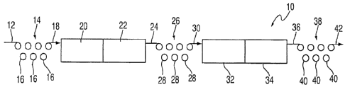
FIG I is a schematic vieNv of a typical oven confil-Iuration employed
in the drawincy ofpolyethylene fibers.
FIG 2 is a schematic view of the oven conftguration of ihis invention
which is useful in the drawing of taltrahieh moiecular weight polyethylene
fibers.
3
CA 02634713 2008-06-20
WO 2007/078569 PCT/US2006/046766
DETAILED DESCRIPTION OF THE INVENTION
The present invention comprises a heating apparatus for draxving
ultrahigh molecular weight polyolefin fibers and a process for drawing such
fibers.
For the purposes of the present invention, a fiber is an elongate body
the length dimension of which is much greater that the transverse dinlensions
of
Nvidth and thickness. Accordingly, the term "fiber" ineludes one, or a
plurality
af. monofilament, multifilarllent, ribbon, strip, staple and other forms of
chopped, cut or discontinuous fiber and the like having regLllar or irregular
cross-
sections. The term ''tibeC' includes a plurality of any of tfle fore~oin<~ or
a
combination thereof. A yarn is a continuous strand comprised of many fibers or
filaments.
The cross-sections of fibers useful llerein may vary ividely. They
may be circular, flat or oblong in cross-section. They may also be of
irregular or
rel-.1ular nlulti-lobal cross-section having one or nlore re"ular or irregular
lobes
projecting ti=om the linear or longitudinal axis of the tibers. It is
preferred that
the fibers be of substantially circular, flat or oblont, cross-section, most
preferably substantially circular.
Ultrahigh molecular weight polyalefins useful in the present Invelltloll
include polyethylene, polypropylene, poly(butene-1), poly(4-methyl-pentene-
I),
their copolynlers, blends and adducts. These polynlers typically have an
intrinsic viscosity when measurecl in decalin at I35 C of ti=om about 5 to
about
45 dl/b.
preferably, the feed yarn to be drawn comprises a polyethylene having
3p an intl-insic viscosity in decalitl of fi-om about 8 to 40 dl/g, nlore
preferably fronl
abaut 10 to 30 dl/~, and nlost preferably ffl=om about 12 to 30 dl/g.
Preferably,
the yarn to be drawn cotnprises a polyethylene having fewer than about ane
methyl group per thousand carbon atoms, nlorc preferably fewer than 0.5 methyl
4
CA 02634713 2008-06-20
WO 2007/078569 PCT/US2006/046766
groups per thousand carbon atoms, and less than about I wt. % of other
constituents. The ultrahigh molecular %veight polyoletins may contain small
amounts. generally less than about 5 weibht percent, and pi-efei-abiy less
than
about 3 weight percent, of additives such as anti-oxidants, thermal
stabilizers.
i colorants, tlow pronzoters, solvents, and the like.
The gel-spun polyethylene fibers to be drawn in the process of the
invention may have been previously drawn. or they may be in an essentially
undrawn state. The process for forming the gel-spun polyethylene teed yarn can
t 0 be one of the processes described. for example, by any of U.S. Patent
Numbers
4,551;296, 4,663,10 l. 5,741,451. and 6,448,659.
In the case of polyethylene suitable fbers are those of weight average
molecular weiyht of at least about I 50,000. preferably at least abaut one
million
ts ancl more preferably between about two million anci about five million. ln
the
case of high molecular Nveight polypropylene fibers, these may have aNveit'ht
average molecular weiglit at least about 200,000. prefei-abiy at least about
one
nlillion and more preferably at least about two inillion.
20 The tenacity of the feed yarn may range from about 2 to 76, preferably
fi=om about 5 to 66, more preferably fi=om about 7 to 51, grams per denier
((r/d)
as measured b), ASTM D2256-97 at a gause length of 10 inches (25.4 cm) ancl at
a stt-ain rate of I00%/min.
25 In the following description reference is typically made to polyethylene
fibers but it should be understood that such discloscn=e also applies to other
polyolefin tibers.
With i-eference to Fig. 1. there is sliown in schematic view a typical
;u di-awin- operation 10 for ultrahigh moleculai- weight polyethylene yarn.
Yarn 12
is fed fi=om a source (not shown) and is passed over a tirst set 14 of rolls
16.
These rolls are typically heated to a desired temperature. The yarn 18 exiting
the
rolls is fed into four adjacent horizontal ovens, only two of which 20, 22 are
shown. These ovens may be hot air circulatin(T ovens. The yarn 24 exitinc, the
CA 02634713 2008-06-20
WO 2007/078569 PCT/US2006/046766
first set of ovens then passes over a second set 26 of rolls 28 ancl is drawn
as
yarn 30. Yar-n 30 is then fed into two n-rore adjacent ovens 32, 34, which may
also be hot air circulating ovens, and the yarn 36 exiting oven 34 is then {ed
over
a third set 38 of rolls 40 and is again drawn to the desired amount. The
tinished
yarn 42 is then fed to a wind up station (not shown). By employing three sets
of
rolls, the frbers are subjected to a two stage drawing oper-ation.
With reference to Fig. 2, there is shoxvn in schematic viexv the heating
apparatus 110 of this invention. Ultrahigh niolecular weight polyethylene yarn
ro 112 is fed from a source (not shown) and is passed over- a first set 114
ot'cir-iven
rolls 116. These rolls need not hc heated, although preferably the first few
rolls
ai-e not hcated and the remainint, rolls are heated to preheat the tibers
prior to
draxving. Although a total of 7 rolls is sliown in Fig. 2, the ninnber of
rolls may
be hic,her or lower. depending upon the desired configuration. The yarn 118 is
fed into six adjacent liorizontal ovens 120, 122, 124, 126. 128, 130, all of
which
preferably are hot air circrilating ovens. The yarn is preferably
not.supported in
the ovens. Yarn 132 esiting last oven 130 then passes over a second set 134 of
driven rolls 136, and is drawn into flnished yarn 138. The second set 134 of
i-olls 136 should be cold so that the finished yarn is cooled to at least
below
about 90 C under tension to preserve its orientation and morphology. "1'hc
number of rolls in second set 134 rnay be higher or lower tlian that the 7 r-
olls
shown in Fig. 2. and may be the same or different fi-orii the number of i-olls
in
tir=st roll set 114. Yarn 138 exiting second roll set 134 is then fed to a
wind up
station (not shown). By employing, only two sets of rolls. the tibers are
sul?jected to a single stage drawina operation. The fibers are drawn between
tirst
t-oll set 114 and second r-oll set 134. The tension is adjusted so that the
tiber-s
rieed riot be supported in the ovens. Thus. there is no need for idler i-olls
or- other
supporting devices in the various ovens.
It can be seen that in the embodiment of this invention as shown in
Fi-. 2 is a simpler design in which only two sets of rolls ai-e needed. The
midclle
set of rolls of the typical apparatus has been elirninated and replaced by two
additional hot air ovens. In addition, not all of the inlet set of rolls need
to be
heated, and only the rolls closest to the oven entr=ance rnay be heated. For
6
CA 02634713 2008-06-20
WO 2007/078569 PCT/US2006/046766
example. in one einbodiment with a nine set roll configuration only the last
three
rolls closest to the oven entrance are preferably heated.
In an alternate embodiinent, the center ovens (124; 126) are not
.5 included in tlie heating apparatus, but the middle set of rolls of the
typical
configtu=ation is eliminated and only a total of four horizontal ovens (120.
122,
128, 130) are employed.
The number and size of the ovens employed in the heating apparatus
of this invention may vary. Preferably there are either four or siX ovens
alignecl
in a liorizontal n-ianner. These ovens may vary in length. For example, each
oven may be from about 10 to about 16 feet (3.05 to 4.88 meters) loncr, moi-e
preferably froin about I I to about 13 feet (i.35 to 3.96 meters) lon;~,~.
Their
xvicltli may be any suitable width.
It has been found by thermal imaging meast=ements and yarn speed
meast=ements that in the typical drawing process the yarn that is heated by
the
Frst set of rolls has already cooled down before it reaches the tirst set of
ovens
(ovens 20, 22). As a result, part of the first oven set is used to heat the
yarn
rather than draNv the yarn. While the second set of rolls 26 does heat up the
yarn
again, the yarn has already begun to cool before it reaches the second set of
ovens (ovens 32, 34). Similarly; part of the second oven set is used to heat
the
yarn rather than draw the yarn. This process in which the yarn is subject to
heat.
cool, heat, cool steps lias been found to be not as effiicient as desired to
achieve
2-5 the high draw ratio needed to obtain high ultimate tensile strenl;th
(UTS). high
tenacity and high modulus. In addition, the operation yield is reduceci ancl
the
capital cost is increased due to the need for three sets of rolls.
It has been found that by eliminating the niiddle set of rolls the yarn
is not subject to the heat. cool, heat, cool process steps of the typical
process.
Rather, the yarn maintains the heat needed for continuous drawing of the yarn.
Thus, yarn can be produced at higher speeds and the-yarn can have improved
tenacity, modulus and ultimate tensile strength. The straight-Iine oven
arrangement also increases operation efficiencv.
7
CA 02634713 2008-06-20
WO 2007/078569 PCT/US2006/046766
It can be seen that the heating apparatus perrnits a continuous, single
stage drawing of the flber or yarn under heat Nvith only the trse of two sets
of
rolls. In addition, the apparatus and process of the invention can be operated
to
draw the fiber away from the masitntun draw ratio in order to reduce the
potential for broken filaments.
The temperature and speed of the varn through the heating apparatus
rnay be varied as desired. For example, one or more temperature controllecl
zones may exist in the ovens, with each zone havinc, a temperature of fr=om
about
125 C to about 160 C, more preferably fi=om about 130 C to about 150 C.
Preferably the temperature within a zone is controlled to vary less than -L2 C
(a
total less than 4 C), more preferably less than :I:1 C (a total less than 2
C).
The drawing of yar-n generates heat. It is desired to have effective
heat transmission between the yarn and the oven air. Preferably. the air
circulation within the oven is in a turbulent state. The time-averaged air
velocity
in the vicinit), of the yarn is preferably from about I to about 200
meters/min.
mor=e preferably from about 2 to about 100 met:ers/min, and most pr-ef'erablv
1'rom
about 5 to about 100 nieters/min.
As pointed out above, the yarn path in heatinc, apparatus 1l0 is
preferably in an approxirnate straight line from inlet to outlet of the
various
ovens. The yarn tension profile may be adiusted by adjusting the speecl of the
various rolls or by adjusting the oven temperature profile. Yarn tension may
be
inereased by increasing the difference between the speeds of consecutive
driven
rolls or decreasing the temperature in the oveiis. Preterably, the yarn
tension in
the ovens is approximately constant, or is increasing through the ovens.
Typically, multiple packages of gel-spun polyethylene yarns to be
drawn are placed on a creel. Multiple varns ends are fed in parallel i7rom the
creel through the first set of r-olls that set the feed speed into the
drawin"; oven,
ancl thence through the ovens and out to the second set of rolls that set the
yarn
exit speed and also cool the yarn under tension. The tension in the yarn
during
8
CA 02634713 2008-06-20
WO 2007/078569 PCT/US2006/046766
cooling is maintained suffiicient to hold the yarn at its drawn lensth
neglecting
thermal contraction.
The ovcrall draw ratio of the fibers inay vary, depending on the
desired properties of the fibers. For example; the draw ratio may ran~e from
about 1.1:1 to about 15:I, inore preferably troin about 1.2:I to about 10:1.
and
inost preferably fi=om about 1.5:1 to about 10:1.
The speed of the fibers through the heatinlgr apparatus of this
It~ invention may also vary. For example, typical lines speeds as measured by
the
speed of the second set of rolls may be fi=om about 20 to 100 nieters/min.,
morc
preferably from about 30 to about 50 nietershnin. The line speed is also
dependent on the desired denier of the yarn.
The apparatus and process of this invention are useful to produce
Iiigh tenacity fibers. As used herein, the term " high tenacity fibers" means
fibei-s
which have tenacities equal to or greater than about 7 b/d. Preferably, these
fibers have initial tensile moduli of at least about 150 g/d and energies-to-
break
of at least about 8.I/( as measw-ed by ASTM D2256. As used herein, the terms
"initial tensile modulus' . "tensile modulus" and "niodulus" mean the inodulus
of
elasticity as measured by ASTM 2256 foi- a yarn.
Depending upon the formation technique, the draw ratio ancl
temperatures, and other conditions, a variety of properties can be imparted to
these fibers. The tenacity of the polyethylene fibers are at least about
7(1/cl.
preferably at least about 15 g/d, more preferably at least about 20 g/d, still
more
preferably at least about 25 g/d and most preferably at least about 30 g/d.
Siniilarly, the initial tensile modulus of the fibers. as measured by an
lnstron
tensile testing machine, is preferably at least about 300 g/d, more preferably
at
least about 500 g/d, still more preferably at least about 1,000 ~~/d and most
preferably at least about 1.200 g/d. In a most= preferred embodiment, the
fibers
after drawing have a tenacity of at least about 35 -/d and a modulus of at
least
about 1.200 g/d. Many of the iilaments have melting points higher than the
melting point of the polymer froni which they were formed. Thus, for example.
9
CA 02634713 2008-06-20
WO 2007/078569 PCT/US2006/046766
high molecuiar weight polyethylene of about 150.000; about one million and
about two million molecular weight generally have melting points in the bulk
of
138 C. The highly oriented polyethylene filaments made of these materials have
melting points offrom about 7 C to about I3 C; higher. Thus, a slight increase
in
meltin ; point reflects the crystalline perfection and higher crystalline
orientation
of the tilaments as compared to the bulk polymer.
The resultatlt yarns may have any suitable denier. such as from about
50 to about 3000 denier, tnore preferably trom about 75 to about 2000 denier.
tn Examples of fine denier products include those of 75, 100. 130, 150. 180,
215,
375 and 435 denier. Examples of hi~h denier products include 900, 1100 and
1300 denier. The feed yarn denier is chosen depending on the desired clenier
of
the yarn. For example, to produce a 1300 denier yarn the feed yai-n ma;, be
2400
denier, and thus the draw ratio is about I.85:1. To produce a 375 denier
product,
t 5 the feed yarn may be 650, with a draw ratio of about 1.73.
The yarns produced by the apparatus and process of this invention
niay be used in a variety of applications for which such yarns are suitable.
TheN'
are useful in impact absorption and ballistic resistant products; such as
bocly
20 armoi- (bullet resistant vests and the like), helrnets, aircraft shields
and seats.
composite spoi-ts equipment, and in fishing line, sails, ropes. sutures and
fabrics
woven, knitted, braided or non-Nvoven). Typical non-Nvoven fabrics
inciude a unidirectionally ai-ray of oriented yarns. Fabt-ics formed fi=om
such
yarns may be used together with a matrix resin. They yarns mav be blencleci
25 Nvith other types of yarns, both high strength and conventional stren(th
yarns.
The following non-liniiting examples are presented to pi-ovicle a moi-e
complete Luiderstanding of the invention. The specific techniques. conditions.
materials; propoi-tions and reported data set forth to illustrate the
principles of the
30 invention are exemplary and should not be construed as limiting the scope
of the
invention.
t ~a
CA 02634713 2008-06-20
WO 2007/078569 PCT/US2006/046766
EXAMPLES
Example 1 (comrmrative)
Ultrahigh molecular xveight polyethylene fibers are drawn in a two
stage draw in an oven configi=ation which includes a first set of four ovens
and a
i second set of two ovens, with a first set of rolls, an intermediate second
set of
i-olls and a third set of rolls in a inanner as depicted in Fig. I.
Tiie len;th of each oven is 12 feet (3.66 m) so the first set of 4 ovens
totals 48 feet (14.63 rn) and the second set of ovens totals 24 feet (7.32 m).
The temperature of the rolls is as follows: first set = 125 C; seconci
to set = I25 C and the third set = 25 C. The temperatures of the tirst and
second
sets of ovens are 150 C.
The starting denier is 2400 and the final denier is 1100. The draw
ratio is 2:2:1. The speed of the first set of rolls is 16 rr-/min, the speed
of the
second set is 26 m/min and the speed of the third set ot rolls is 34 m/inin.
t~ The tenacity of the retiultin;,~ fiber is trom 35 to 37 ~~/d and the
initial
tensile modulus is i 150 to 1200 (Y/d.
Examnle 2
In this esample, ultrahibh molecular weibht polyethylene tibers are
draxvn in a single stage draw in an oven contiguration Nvhich includes a set
ofsia
20 horizontally aligned ovens, in a manner as depicted in Fig. 2. Only two
sets of
rolis are used, an inlet set (first set) and an exit set (second set).
The length of each oven is 12 feet (3.66 meters), so the total length of
the 6 ovens is 72 feet (21.95 meters).
The tii-st set of rolls has a temperature of 125 C, and the second set ot-
25 i-ol Is has a temperature of 25 C. The temperature of each oven is 150 C.
Il
CA 02634713 2008-06-20
WO 2007/078569 PCT/US2006/046766
The starting denier is 2400 denier and the final denier is 1100 clenier
ivitli a draw ratio 2:1:1. The speed for the first set of rolls is 20 m/min
and the
speed of the second set of rolls is 44 m/min.
The tenacity of the resultinl; fiber is from 37 to 39 a/d and the initial
tensile modulus is 1250 to 1300 g/d.
It can be seen that the heatinb apparatus eniployed in Example 2 and
operated in a manner of Example 2 provides tibers of higher tenaeity and
modulus than the fibers of the oven configuration of' Example 1. Also. the
line
speed of Example 2 is significantly higher than in Esample I so that there is
an
l u increase in the productivity of the process.
It can be seen that the present invention provides an apparatus ancl
method for forming drawn Lrltrahigh molecular weight polyolefin fibers ancl
yarns, such as polyethylene fibers and yarns, in a cost-effective and
operationaily
fi=iendly manner. The resultant yarns have the desirable proper=ties to be
usel'ul in
a variety of demanding applications.
Havina thus described the invention in rather full detail, it will be
understood that such cletail need not be strictly adhered to but that
ftn=tlier
2t- changes and modifications may sug;est themselves to one skilled in the
art, all
I'allin- within the scope of the invention as detined by the subjoined claims.
12