Note: Descriptions are shown in the official language in which they were submitted.
CA 02634913 2008-06-23
WO 2007/075918 PCT/US2006/048845
DISTRIBUTED SYSTEM AND METHOD FOR
DIAGNOSING NETWORK PROBLEMS
TECHNICAL FIELD
[0001] The present invention relates to network monitoring systems and
methods. More
particularly, the present invention relates to a distributed system and method
for diagnosing
problems in a signal at an endpoint in a network system, wherein the
capabilities of a
conventional network probe or analyzer may be replicated as virtual functions.
BACKGROUND ART
[0002] The use of network test equipment such as probes and analyzers for
diagnosing
network problems is well established. To facilitate the identification of
network problems, such
devices are attached to a packet network to capture and analyze packets
passing the monitored
point and to report or display data derived from the analysis of the packet
contents. Because
placing test equipment at remote endpoints is expensive and impractical, it is
common to attach
such probes and analyzers to networks at points where there is a large amount
of aggregated
traffic.
[0003] For example, a residential voice over IP service comprises a large
number of simple
endpoint devices such as residential gateways, analog telephone adaptors, IP
phones or soft
phones (collectively referred to as customer premise equipment). Such customer
premise
equipment is attached to an IP network via a broadband network connection.
This allows voice
over IP packets to be transferred between the customer premise equipment for
one subscriber
and the customer premise equipment for another subscriber. Congestion on
broadband network
connections such as DSL or cable modems is common, and results in intermittent
quality
problems on voice over IP calls. The manager of the residential voice over IP
service therefore
needs to be able to identify and resolve these problems. However, it is
generally cost
prohibitive to place conventional network probes or analyzers at the customer
premise.
[0004] A further problem results from the potentially large number of
subscribers, which
may reach into the tens of millions. For example, if subscriber A reports that
he or she has been
experiencing problems, then a network manager may be assigned to investigate.
Because IP
problems are transient in nature, the network manager cannot reliably expect
that problems will
occur at the time he or she checks the subscriber's connection. Moreover, it
is generally
impractical for the network manager to monitor the connections of all the
subscribers that have
1
CA 02634913 2008-06-23
WO 2007/075918 PCT/US2006/048845
reported problems in the hope of catching a transient problem.
[0005] A need therefore exists for an improved network monitoring system and
method that
overcomes these problems.
DISCLOSURE OF THE INVENTION
[0006] The present invention answers this need by providing a system and
method wherein
a large scale residential voice over IP or IPTV service, IP cellular service,
or large enterprise
voice over IP deployment can be effectively monitored, thereby allowing a
network manager to
capture infomzation relating to transient problems using functionality
previously limited to large
network probes and analyzers.
[0007] In accordance with the present invention, a distributed system for
diagnosing
problems in a signal at an endpoint in a network comprises a quality of
service monitor located
at the endpoint and a system manager located generally remote from the
endpoint. The quality
of service monitor includes a call quality analysis component, a parameter
capture component,
and a problem reporting component. The call quality analysis component
monitors values of
call quality parameters in order to detect a quality problem in the signal.
Upon detection of the
quality problem, the parameter capture component samples values of call
quality parameters at
a shortened sampling interval. The parameter reporting component incorporates
the values
sampled by the parameter capture component into a problem call quality report
for transmission
over the network. The system manager receives and stores the problem call
quality report for
subsequent review.
[0008] In one embodiment, a standard reporting component is provided to sample
values of
call quality parameters at a normal sampling interval, incorporate the sampled
values into a
standard call quality report, and transmit the standard call quality report
over the network to the
system manager. Thus, a normal sampling interval is used while monitoring for
a quality
problem associated with the call signal and, if a quality problem is detected,
a shortened
sampling interval is used in order to gather sufficient data to diagnose the
quality problem.
[0009] In another embodiment, the call quality analysis component detects a
quality
problem by comparing the monitored values of the quality parameters to a
threshold. If the
monitored values of one or more of the quality parameters exceed the
threshold, a quality
problem is detected and the parameter capture component is signaled to begin
sampling at the
shortened sample intervals.
2
CA 02634913 2008-06-23
WO 2007/075918 PCT/US2006/048845
[00010] In further embodiments, the problem reporting component incorporates
the values
sampled by the parameter capture component into the problem call quality
report by performing
quantizing and compression operations on the sampled data.
[00011] It is thus an object of the present invention to provide a system and
method wherein
very large numbers of endpoints may be monitored when problems occur to obtain
useful,
detailed data for troubleshooting such problems.
[00012] Further objects, features and advantages will become apparent upon
consideration of
the following detailed description of the invention when taken in conjunction
with the drawings
and the appended claims.
BRIEF DESCRIPTION OF THE DRAWINGS
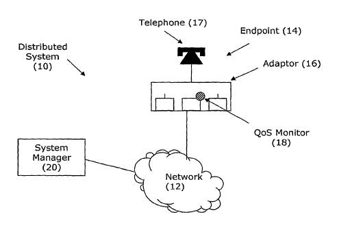
[00013] FIG. I is a relational diagram showing a distributed system for
diagnosing network
problems in an embodiment of the present invention.
[00014] FIG. 2 is a schematic diagram of an analog telephone adaptor used in
an
embodiment of the present invention.
[00015] FIG. 3 is a schematic diagram of a quality of service =monitor in an
embodiment of
the present invention.
BEST MODE FOR CARRYING OUT THE INVENTION
[00016] With reference to FIG. 1, a distributed system 10 in accordance with
the present
invention is shown for diagnosing problems in a signal at an endpoint 14 in a
network 12. The
distributed system 10 comprises a quality of service monitor 18 located at the
endpoint 14 and a
system manager 20 located generally remote from the endpoint 14. In the
embodiment shown,
the quality of service monitor 18 is included in an analog telephone adaptor
16, wherein the
analog telephone adaptor 16 is connected to a standard telephone 17. It will
be appreciated that
the quality of service monitor 18 may be associated with any suitable wired or
wireless device
at the endpoint 14, such as an IP phone, a "softphone," a personal digital
assistant (PDA), a
mobile telephone, a personal computer, a residential gateway, a cable system
MTA, an IPTV
set top box, or the like, and may be included in an external unit coupled to
the endpoint device
or as an internal component of the endpoint device.
[00017] With reference to FIG. 2, the analog telephone adaptor 16 comprises a
network
interface 22, a jitter buffer 24, a voice over IP conversion component 26, a
signaling component
3
CA 02634913 2008-06-23
WO 2007/075918 PCT/US2006/048845
28, and a telephone interface (e.g., voice ports) 30. The network interface 22
is connected to
the network 12, such as by an Ethernet connection. The telephone interface 30
is connected to
the telephone 17. The voice over IP conversion component 26 converts the
analog voice
signals received from the telephone 17 to a stream of voice over IP packets
and transmits the
packets over the network 12. In addition, the voice over IP conversion
component 26 converts
a stream of voice over IP packets received from a remote voice over IP system
(not shown) to
analog voice signals and transmits the analog signals to the telephone 17. The
signaling
component 28 establishes new calls and terminates completed calls by sending
messages to the
system manager 20. The signaling component 28 may also send messages that
incorporate call
quality (Quality of Service (QoS)), information and may direct these messages
either to the
system manager 20 or to a separate collection system.
[00018] The quality of service monitor 18 is incorporated into the analog
telephone adaptor
16 to measure the quality of the voice over IP calls at the endpoint 14 and to
generate call
quality reports. Such call quality reports are sent over the network 12 to the
system manager 20
using protocols such as RFC3611 (RTCP XR), SIP, or other suitable protocols as
is known in
the art. The quality of service monitor 18 may operate as described in U.S.
Patent No.
6,741,569, entitled "Quality of Service Monitor for Multimedia Communications
System," U.S.
Patent No. 7,058,048, entitled "Per-Call Quality of Service Monitor for
Multimedia
Communications System," and/or U.S. Patent No. 7,075,981, entitled "Dynamic
Quality Of
Service Monitor," which are incorporated herein by reference.
[00019] With reference to FIG. 3, the quality of service monitor 18 includes a
call quality
analysis component 40, a parameter capture component 42, a problem reporting
component 44,
and a standard reporting component 48. The call quality analysis component 40
is configured
to sample values of quality parameters associated with the call signal. Such
quality parameters
might include measured, calculated, or estimated parameters such as estimated
MOS score, R
factor, delay, packet loss, jitter, signal level, noise level, echo level,
distortion, absolute packet
delay variation, relative packet to packet delay variation, short terrn delay
variation, short term
average delay, timing drift, and/or proportion of out-of-sequence packets.
[00020] As explained in further detail below, the quality of service monitor
18 has two
modes of operation: (1) a standard mode wherein quality parameters are sampled
and call
quality reports are transmitted at normal intervals; and (2) a problem mode
wherein quality
parameters are sampled and call quality reports are transmitted at shorter
intervals, i.e., at a
4
CA 02634913 2008-06-23
WO 2007/075918 PCT/US2006/048845
higher frequency. The use of a higher sampling and reporting frequency is
desired to obtain
sufficient data for diagnosing many types of network problems. However, the
use of a higher
sampling and reporting frequency at all times would result in an excessive
volume of call
quality reports being transmitted on the network 12 and would ultimately
create so much
network traffic that quality would be greatly reduced. In this regard,
although it is desirable to
monitor the network quality at many endpoints to detect transient problems,
the resulting
volume of call quality report packets on the network would be equal to the
number of
monitored endpoints multiplied by the number of call quality report packets
per second - a
volume that is excessive in a network of any size. Advantageously, in
accordance with the
present invention, a normal sampling and reporting frequency is used while
monitoring for a
quality problem associated with the call signal and, if a quality problem is
detected, a higher
sampling and reporting frequency is used in order to gather sufficient data to
diagnose the
quality problem.
[00021] With continuing reference to FIG. 3, in the standard mode the call
quality analysis
component 40 continuously monitors the quality parameters associated with the
signal and the
standard reporting component 48 samples the quality parameters at normal
sample intervals,
such as every 5 to 20 seconds. The standard reporting component 48
incorporates the sampled
values into standard call quality reports and transmits the standard call
quality reports to the
system manager 20 every 5 to 20 seconds and/or at the end of a call. The
system manager 20
receives the standard call quality reports and stores the standard call
quality reports in a
database for subsequent review.
[00022] If the call quality analysis component 40 detects a quality problem,
the problem
mode is triggered. In the problem mode, the parameter capture component 42
samples the
quality parameters associated with the signal at shortened sample intervals,
such as every 200 to
500 milliseconds. The problem reporting component 46 incorporates the values
sampled by the
parameter capture component 42 into problem call quality reports and transmits
the problem
call quality reports to the system manager 20. The system manager 20 receives
the problem call
quality reports and stores the problem call quality reports in a database for
subsequent review.
[00023] In one embodiment, the call quality analysis component 40 detects a
quality problem
by comparing the monitored values of the quality parameters to a threshold. If
the monitored
values of one or more of the quality parameters exceed the threshold, a
quality problem is
detected and the parameter capture component 42 is signaled to begin sampling
at the shortened
CA 02634913 2008-06-23
WO 2007/075918 PCT/US2006/048845
sample intervals. The call quality analysis component 40 may also be
configured to identify
which one or more of the quality parameters violated the threshold. Based on
the identity of
such a problem quality parameter, the parameter capture component 42 may set
the shortened
sampling interval to a preferred interval. For example, if the problem quality
parameter is
identified as jitter, it may be useful to have a much finer resolution view of
the data. Thus, the
parameter capture component 42 could set the shortened sampling interval for
jitter problems to
a shorter time period than for other types of problems. The identity of the
problem quality
parameter may also be used by the parameter capture component 42 to select the
specific
quality parameter(s) for sampling at the shortened sampling interval. For
example, if the
problem quality parameter is identified as packet loss, it may be useful to
obtain data relating to
jitter to determine whether the packet loss is due to congestion. Thus, the
parameter capture
component 42 could select jitter as a quality parameter for sampling at the
shortened sampling
interval.
[00024] The problem reporting component 46 may be configured to incorporate
the values
sampled by the parameter capture component 42 into the problem call quality
report upon
termination of the call. In another embodiment, the parameter capture
component 42 is
configured to store the sampled values of the quality parameters in an array
44, and the problem
reporting component 46 is configured to incorporate the values sampled by the
parameter
capture component 42 into the problem call quality report upon filling the
array 44.
[00025] In one embodiment, the problem reporting component 46 incorporates the
values
sampled by the parameter capture component 42 into the problem call quality
report by
performing quantizing and compression operations on the sampled values. In
particular, the
problem reporting component 46 may be configured to quantize the values
sampled by the
parameter capture component 42, to store the quantized values in a compressed
data block; and
to incorporate the compressed data block into the problem call quality report.
[00026] Such quantization may include associating each of the values sampled
by the
parameter capture component 42 with one of a series of value ranges and
quantizing the values
sampled by the parameter capture component 42 based on the associated value
ranges. For
example, MOS-LQ values sampled by the parameter capture component 42 may be in
the
numerical range of I to 5, where a value over 4 indicates good quality. While
it is useful to
identify small changes in MOS when the value is higher than 3, it is less
useful to identify small
changes when the MOS value is low. The sampled MOS values may therefore be
usefully
6
CA 02634913 2008-06-23
WO 2007/075918 PCT/US2006/048845
quantized into value ranges, such as:
000 = 1.00-2.00
001 = 2.01-2.80
010 = 2.81-3.30
011 = 3.31-3.50
100 = 3.51-3.70
101 = 3.71-3.90
110 = 3.91-4.10
111 = 4.11-5.00
[00027] These value ranges may be represented in a compressed form as a "0" if
a given
MOS value was the same as a previous MOS value, or as a"1" followed by a three
bit
codeword, as listed above, if the given MOS value was different from a
previous MOS value. It
will be appreciated that other quantization or encoding schemes may be used,
such as
differential encoding, Huffman coding, Ziv-Lempel coding, or other such
algorithms known to
practitioners in the art.
[00028] In accordance with the present invention, it is possible to represent
a period of 60
seconds sampled at a rate of 500mS in about 123-480 bits per parameter encoded
(an average
size of about 200 bits per parameter). This would allow a period of 60 seconds
of 4 such
parameters sampled at 500mS to be represented in a compressed data block of
approximately
100 bytes.
[00029] The problem reporting component 46 incorporates the compressed data
block of
sampled data into a problem call quality report and transmits the problem call
quality report to
the system manager 20 for storage. At some later point in time, the compressed
data block may
be retrieved and decoded to facilitate the troubleshooting of problems.
[00030] Consequently, when the call quality analysis component 40 detects a
quality
problem during a call, the parameter capture component 42 could immediately
start to sample 4
to 8 key call quality parameters at a sampling interval of 200-500mS for a
period of 30-60
seconds, and the problem reporting component 46 could store the sampled data
in a compressed
data block. At the end of the call the compressed block of diagnostic data may
be reported back
to the system manger 20 and stored in a database. Because these steps are
immediately invoked
when a quality problem is detected, there is a high likelihood that the
quality problem is still
persisting while the data is being captured and that the samples will include
information on the
quality problem. Accordingly, the present invention provides the system
manager 20 with a
small block of compressed, sampled data on every call that experienced a
problem, while
7
CA 02634913 2008-06-23
WO 2007/075918 PCT/US2006/048845
keeping the overhead for obtaining this data at a minimum.
[00031] At a future time when a network administrator wishes to troubleshoot
the already
completed call, he can retrieve the compressed data block from the call
database at the system
manager 20 and graphically represent the sampled data for visual
interpretation. Because the
quality parameters are sampled synchronously with each other, it is possible
to represent the
sampled quality parameters as a series of aligned time charts.
[00032] As a result, the present invention provides a system and method
wherein very large
numbers of endpoints may be monitored when problems occur to obtain useful,
detailed data for
troubleshooting such problems. Further, in accordance with the present
invention only a small
additional block of data is required to be incorporated into an existing
message to achieve such
benefits. In addition, the solution delivered by the present invention is
scaleable to millions of
endpoints and greatly facilitates the process of troubleshooting transient and
unpredictable
problems in very large networks.
[00033] Although the invention herein has been described with reference to
particular
embodiments, it is to be understood that these embodiments are merely
illustrative of the
principals and applications of the present invention. Accordingly, while the
invention has been
described with reference to the structures and processes disclosed, it is not
confined to the
details set forth, but is intended to cover such modifications or changes as
may fall within the
scope of the following claims.
8