Note: Descriptions are shown in the official language in which they were submitted.
CA 02634914 2008-06-23
WO 2007/072045 PCT/GB2006/004901
1
Aircraft Passenger Seat
The present invention relates to an aircraft passenger seat, particularly but
not
exclusively to an aircraft sleeper seat convertible into a substantially flat
bed.
Background to the Invention
Examples of prior art aircraft sleeper seats are disclosed in the applicant's
patent
publications WO 96/18537 and W000/21831, embodiments of which include the
current British Airways First and Club World seats respectively. Both of these
seats can
be converted into a flat, horizontal bed, and have enjoyed great commercial
success.
However, there is intense competition to provide ever-greater comfort and
space for
aircraft passengers.
Passenger seats for aircraft are subject to stringent design constraints, many
of which
are not applicable to seats for other vehicle types. One problem is the need
to meet the
relevant safety standards for aircraft passenger seats, such as the 16g test
that requires
seats to survive deceleration of 16g in a takeoff/landing position. Another
problem is
the need to minimize the weight of the seat, since carrying extra weight on an
aircraft
increases fuel consumption and therefore monetary and environmental cost.
Hence, the
seat must be both strong and light.
Another problem relates to the use of space. Any given aircraft has a maximum
area for
passenger seating, which must be used in the most space-efficient manner
possible so as
to maximize the seating area and legroom available to each passenger, while
allowing
unimpeded exit from the seat. It is also important for cost reasons to fit as
many
passenger seats as possible in the available area.
Another problem relates to the level of comfort of the seat. Aircraft
passenger seats may
be used for day flights, in which the passenger will want to work, eat and/or
relax, and
night flights during which the passenger will want to sleep. Preferably, an
aircraft
passenger seat should be able to adopt comfortable positions for all of these
activities,
yet also be able to meet the relevant safety standards in a takeoff/landing
position.
Another problem relates to the psychological and/or social needs of aircraft
passengers,
who may desire privacy while working, eating or sleeping, or may wish to
interact with
CA 02634914 2008-06-23
WO 2007/072045 PCT/GB2006/004901
2
a travelling companion. There are also some arrangements that are undesirable
for
aesthetic and/or psychological reasons; for example, it is preferred that
parts of the seat
mechanism are not visible to the passenger.
Patent publication EP-A-1 116 654 (BE Aerospace) discloses an aircraft
passenger
sleeper seat that can adopt fully upright, semi-reclined or lounge and fully
reclined or
sleep positions. The seat includes an ottoman that functions as a foot or leg
support, and
has a top cushion and a pivoting legrest cushion.
Patent publication US 2,583,223 (Mayer) discloses a foot and leg rest for
passenger
vehicles, having a rearwardly inclined foot rest position and an elevated,
forwardly
inclined leg rest position.
Patent publication WO 98/36967 (Singapore Airlines) discloses an aircraft
passenger
seat with armrests that are lowered as the seat reclines, so as to lie flush
with a seat
portion in a f-ully reclined position and thereby improve the width available
to the
passenger.
Patent publication no. US 6,692,069 (Beroth et. al.) discloses an aircraft
passenger
sleeper seat in which an armrest pivots forwards as the seat reclines, so as
to be aligned
with a seat bottom in a fully reclined position and thereby improve the width
available
to the passenger. However, this arrangement does not allow the sleeping
surface to be
horizontal.
Statements of the Invention
According to a first aspect of the invention, there is provided an aircraft
passenger
seating arrangement comprising a primary seat having a seat pan and a seat
back, and a
secondary surface positionable opposite and separate from the primary seat,
the
passenger seating arrangement being able to adopt a first, substantially
upright
configuration in which the seat back is substantially vertical, a second, semi-
reclined
configuration in which the seat back is reclined between the horizontal and
the vertical
and a third, fully reclined configuration in which the seat back and seat pan
are
substantially horizontal, wherein in the second configuration the secondary
surface is
angled upwardly to support the lower leg(s) of the passenger and in the third
CA 02634914 2008-06-23
WO 2007/072045 PCT/GB2006/004901
3
configuration, the secondary surface is substantially horizontal and provides
a
substantially flat, continuous sleeping surface with the seat pan and the seat
back.
An advantage of this seating arrangement is that configurations suitable for
sitting
upright, reclining and sleeping can be provided. Hence, the seating
arrangement may be
comfortable for long periods during day or night flights. In the second, semi-
reclined
position the lower leg(s) of the passenger may be fully supported, thereby
providing a
comfortable reclining position without the need for a footrest. Another
advantage is that
these configurations may be provided by means of only three support surfaces
(the seat
back, seat pan and secondary surface), allowing a simple mechanism for moving
the
support surfaces into the different configurations.
Preferably, in the first configuration, the secondary surface is substantially
horizontal
and is displaced both downwards and horizontally towards the primary seat,
relative to
the third configuration, so as to provide a footrest. An advantage of this
arrangement is
that the secondary surface is able to act both as a leg rest, in the second
and third
configurations, and as a foot rest, in the first configuration
Preferably, the secondary surface is pivotable to a substantially vertical,
stowed
position. An advantage of this arrangement is that the second surface may
provide
minimal obstruction to a passenger leaving the primary seat. The secondary
surface may
be pivoted upwardly to the substantially vertical position, which is
advantageous in that
it allows a comparatively long secondary surface and a comparatively short
mechanism
for the secondary surface. Advantageously, the secondary surface may be stowed
up
against a housing, such as that of a seating arrangement of another passenger.
Part of
the mechanism of the secondary seat may be housed within that housing.
The secondary surface is considered to be independently inventive and
therefore,
according to a second aspect of the invention, there is provided a
foot/legrest for an
aircraft passenger seat, the foot/legrest having a support surface and a
mechanism for
securing the support surface in a first, substantially horizontal position and
a second
position at a substantial angle to the horizontal and vertical directions, for
supporting
the lower leg(s) of a passenger seated in the seat in a semi-reclined
position, wherein
the mechanism is arranged to rotate and translate the support surface between
the first
and second positions. The mechanism may include a pivot about which the
support
CA 02634914 2008-06-23
WO 2007/072045 PCT/GB2006/004901
4
surface is rotatable, and means for translating the pivot. Preferably, the
translating
means is arranged to translate the pivot with a vertical component, and most
preferably
to translate the pivot in a direction at an angle substantially intermediate
between the
horizontal and vertical directions.
Preferably, the mechanism is also able to secure the support surface in a
third,
substantially horizontal position displaced in a vertical direction from the
first position.
Preferably, the third position is also displaced in a horizontal direction
from the first
position. An advantage of this arrangement is that the support surface may act
as a leg
rest for the passenger both in a semi-reclined and a sleeping position, while
also acting
as a foot rest for the passenger in an upright sitting position.
Preferably, the mechanism is operable to move the support surface to a
substantially
vertical, stowed position. An advantage of this arrangement is that the
support surface
then provides minimal obstruction to the passenger.
Preferably, the mechanism is arranged to secure the support surface such that
the
support surface is able to move downwardly if a force or torque greater than a
predetermined threshold is applied downwardly to the support surface, and the
support
surface is able subsequently to return to its secured position; in other
words, the
mechanism gives way but is not damaged. An advantage of this arrangement is
that,
when stepped on or sat upon, the support surface at least partially moves out
of the way
of the passenger.
According to another aspect of the present invention, there is provided an
aircraft
passenger seat comprising a seat back, a seat pan and a frame, the seat being
positionable in each of an upright configuration, a reclined configuration in
which the
seat back is reclined relative to the upright configuration and a
substantially flat
configuration in which the seat back and the seat pan form a substantially
flat and
continuous surface, wherein the seat back is guided so as to recline as the
seat back
moves forward relative to the frame, the seat back being connected to the seat
pan by a
pivotal connection between the seat back and the seat pan; and by a torque
transmitting
mechanism for governing the angle between the seat back and the seat pan as
the seat
back reclines. The seat back and/or the seat pan may be guided at least in
part by
engagement with the frame, for example by a pin guided along a track. The
torque
CA 02634914 2008-06-23
WO 2007/072045 PCT/GB2006/004901
transmitting mechanism may comprise a cam mechanism separate from, and
moveable
relative to the frame.
According to another aspect of the present invention, there is provided an
aircraft
passenger seat comprising a seat back and a seat pan, the seat being
positionable in each
5 of an upright configuration and a substantially flat configuration in which
the seat back
and the seat pan form a substantially flat and continuous surface, the seat
having a
retractable armrest having a raised position in which the retractable armrest
overhangs
the seat pan in the upright configuration and a lowered position in which at
least part of
the armrest is located on or immediately above the seat back in the
substantially flat
configuration.
According to another aspect of the present invention, there is provided an
aircraft
passenger seat having a housing separating the seat from an adjacent aircraft
passenger
seat, the housing including a screen arranged to retract automatically in
response to an
electrical signal. The screen may be latched in a deployed position, and the
latch
released in response to the electrical signal. The screen may be latched by an
electrical
latch, and the electrical signal may comprise a reduction or removal of
electrical power
to the electrical latch.
According to another aspect of the present invention, there is provided an
aircraft
passenger seat having a screen between the seat and an adjacent aircraft
passenger seat,
the screen having a transparency dependent on vertical viewing angle, such
that the
screen is not transparent at a low vertical viewing angle but is transparent
at a high
vertical viewing angle.
Brief Description of the Drawings
Embodiments of the invention will now be described with reference to the
drawings
identified below.
Figure la is a perspective view of a seating arrangement in an embodiment of
the
invention, in a first configuration suitable for sitting substantially
upright.
Figure lb is a perspective view of the seating arrangement in a second
configuration,
suitable for takeoff and/or landing.
CA 02634914 2008-06-23
WO 2007/072045 PCT/GB2006/004901
6
Figure lc is a perspective view of the seating arrangement in a third
configuration,
suitable for resting.
Figure 1d is a perspective view of the seating arrangement in a fourth
configuration,
suitable for sleeping.
Figure 2a is a schematic side view of a seating arrangement in an embodiment
of the
invention, in the first configuration suitable for sitting substantially
upright.
Figure 2b is a schematic side view of the seating arrangement in the second
configuration, suitable for takeoff and/or landing.
Figure 2c is a schematic side view of the seating arrangement in the third
configuration,
suitable for resting.
Figure 2d is a schematic side view of the seating arrangement in the fourth
configuration, suitable for sleeping.
Figure 3a is a lateral cross-sectional view of a primary seat of the seating
arrangement
showing the configuration of armrests in a raised position.
Figure 3b is a corresponding lateral cross-sectional view showing the
configuration of
armrests in a lowered position.
Figure 4 is a side view of a reclining mechanism for the primary seat.
Figure 4a shows a detail of the reclining mechanism of Figure 4 in the first
configuration.
Figure 4b shows a detail of the reclining mechanism of Figure 4 in the second
configuration.
Figure 4c shows a detail of the reclining mechanism of Figure of 4 in the
third
configuration.
Figure 4d shows a detail of the reclining mechanism of Figure of 4 in the
fourth
configuration.
Figure 5 is a perspective view of the reclining mechanism.
Figure 6a is a detailed view of the reclining mechanism in the first
configuration.
Figure 6b is a detailed view of the reclining mechanism in the second
configuration.
CA 02634914 2008-06-23
WO 2007/072045 PCT/GB2006/004901
7
Figure 6c is a detailed view of the reclining mechanism in the third
configuration.
Figure 6d is a detailed view of the reclining mechanism in the fourth
configuration.
Figure 7a is a detailed view of a first embodiment of the armrest mechanism in
the
raised position.
Figure 7b is a detailed view of the first embodiment of the armrest mechanism
in the
lowered position.
Figure 7c is a detailed view of a second embodiment of the armrest mechanism.
Figure 7d is a close-up view of the lower surface of the arnirest support in
the second
embodiment.
Figure 7e is a detailed view of a third embodiment of the armrest mechanism,
in a
raised position.
Figure 7f is a detailed view of the third embodiment of the armrest mechanism,
in a
lowered position.
Figure 7g is a detailed view of the third embodiment of the armrest mechanism,
with
the armrest lifted out of the lowered position.
Figure 8 is a perspective view of the support mechanism of the secondary
support.
Figure 9 is a detailed perspective view of the support mechanism.
Figure 10 is a detailed perspective view of a rack and pinion in the support
mechanism.
Figure 11 is a perspective view of the mounting of the support mechanism
within the
housing of a forwardly adjacent seat.
Figure 12 is a plan view of a seat layout in the cabin of an aircraft.
Figure 12a shows an oppositely facing pair of seats in the layout of Figure
12.
Figures 13a and 13b show a privacy screen in raised and lowered configurations
respectively.
Figure 13c show a securing mechanism of the privacy screen.
Figure 14 is a diagram illustrating the dependence of the transparency of the
privacy
screen on vertical viewing angle.
CA 02634914 2008-06-23
WO 2007/072045 PCT/GB2006/004901
8
Detailed Description of the Embodiments
Seating Configurations
In this section, 'horizontal' and 'vertical' are defined with reference to the
floor of the
passenger seating area of the aircraft. As in well-known in the art, the angle
of the floor
relative to the gravitational horizontal is determined by the pitch of the
aircraft, which is
about 15 during takeoff and landing, and about 3 in level flight. When
discussing an
individual seat, 'forward' and 'rearward' are defined with reference to the
direction in
which the passenger faces when seated.
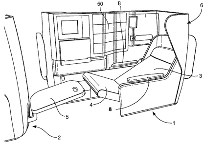
Figures la to 1 d show the same perspective view of a seating arrangement in
an
embodiment of the invention, in different configurations, while Figures 2a to
2d show
the arrangement in schematic lateral view, in the respective configurations.
The seating
arrangement comprises a primary seat 1 and a secondary support 2 opposite the
primary
seat 1. The support surfaces of the primary seat 1 comprise a seat back 3 and
a seat pan
4, while the support surface of the secondary support 2 comprises a
foot/legrest 5. Left
and right arm rests 8a, 8b are disposed either side of the seat pan 4.
The seat back 3 and the seat pan 4 are moveable together between upright,
takeoff/landing, reclined and horizontal configurations by means of a seat
reclining
mechanism, embodiments of which will be described below. In the horizontal and
reclined configurations, the ann rests 8a, 8b drop from a raised to a lowered
position,
under the control of the seat reclining mechanism.
The seat reclining mechanism is at least partially housed within a housing 6,
so that it
does not present a trap hazard to passengers, and is preferably not visible to
passengers
in normal use. The seat back 3 is substantially maintained within the housing
6 in each
of the configurations, so that the seat back 3 does not impinge into space
reserved for
other passengers, and also does not present a trap hazard. The housing 6
partially
surrounds the passenger, which affords a degree of privacy. A retractable
privacy screen
50 is located in a side wall of the housing 6, separating the seat from an
adjacent seat.
A storage drawer 23 is provided within the housing 6, located at floor level.
CA 02634914 2008-06-23
WO 2007/072045 PCT/GB2006/004901
9
The secondary support 2 in this embodiment is configurable independently of
the
primary seat 1 and is not linked to the seat reclining mechanism. The
secondary support
2 can be manually secured in different configurations, as described below.
In the first configuration as shown in Figures 1 a and 2a, the seat back 3 is
at its most
upright position and the seat pan 4 is in its rearmost position. The arm rests
8a, 8b are in
a raised position. The foot/legrest 5 is in a low, horizontal position, in
which
configuration it acts as a footrest. The first configuration is suitable for
sitting upright,
for example while the passenger is working or eating. The seat pan 4 is at
about 10 to
the horizontal, while the seat back 3 is between about 15-20 to the vertical.
In the second configuration as shown in Figures lb and 2b, the seat back 3 is
more
reclined and the seat pan 4 has moved forward and is more inclined relative to
its
position in the first configuration. The angle of reclining of the seat back 3
is about 25-
30 to the vertical and the angle of inclination of the seat pan 4 is about 15-
20 to the
horizontal. One advantage of this configuration is to avoid tipping the
passenger out of
the primary seat 1 during takeoff, where the primary seat 1 faces towards the
rear of the
aircraft. The primary seat 1 meets the required safety standards for takeoff
and landing,
such as the 16g test, in the second configuration.
In the third configuration as shown in Figures lc and 2c, the seat back 3 is
reclined by a
large angle, such as 40-70 , to the vertical, and the seat pan 4 has moved
forward
relative to its position in the second configuration. Again, the angle of
reclining of the
seat back 3 and the corresponding forward movement of the seat pan 4 may be
varied
under control of the passenger, to provide the desired degree of reclining.
The angle of
the seat pan 4 remains substantially constant, about 17 to the horizontal.
The arm rests
8a, 8b have dropped into the lowered position. The third configuration is
suitable for
resting and/or in-flight entertainment. The foot/legrest 5 may be configured
as shown in
an angled position, sloping upwards in the rearward direction by about 15 to
the
horizontal, so as to support the lower leg(s) of the passenger. In this way,
the passenger
is supported in a reclined sitting position, with weight distributed across
the seat back 3,
seat pan 4 and foot/legrest 5. This configuration corresponds to the position
that the
relaxed human body adopts in a weightless environment, and is very
comfortable.
Moreover, passengers who are accustomed to sleeping on their back may find
this
CA 02634914 2008-06-23
WO 2007/072045 PCT/GB2006/004901
configuration suitable for sleeping. As a result of the Z-shaped configuration
of the seat
back 3, seat pan 4 and foot/legrest 5, the overall length that can be
supported in the third
configuration is greater than that supported in the fourth, flat and
horizontal
configuration, so that unusually tall passengers may also find the third
configuration
5 suitable for sleeping. In one specific embodiment, the overall length
supported in the
third configuration is 198 cm (78 inches), while an overall length of 183 cm
(72 inches)
is supported in the fourth configuration.
In the fourth configuration as shown in Figure 1 d and 2d, the seat back 3 and
the seat
pan 4 are substantially horizontal and form a substantially continuous, flat
surface. The
10 arm rests 8a, 8b are lowered, and rest adjacent to the seat back 3. The
foot/legrest 5 may
be configured as shown in a high horizontal position, raised and moved
forwardly
relative to the second configuration. In this position, the foot/legrest 5
forms a
substantially flat, continuous surface with the seat back 3 and the seat pan
4. The fourth
configuration is suitable for sleeping, and preferably provides sufficient
width to allow
passengers to sleep on their sides, back or-front.
Arm Rests
The configuration of the arm rests 8a, 8b enhances the width available to the
passenger
both when sitting, in the first and second configurations, and resting, as in
the third and
fourth configurations. The configuration of the arm rests 8a, 8b in the raised
position is
shown in lateral cross-section in Figure 3a. The armrests 8a, 8b are supported
on
relatively thin, elongate movable armrest supports 9a, 9b that project from
the housing
6. At least the inner edges of the armrests 8a, 8b project inwardly so as to
overhang the
seat pan 4. This arrangement provides a width W1 for the passenger's hips
under the
armrests 8a, 8b greater than the distance D between the armrests 8a, 8b.
The configuration of the arm rests 8a, 8b in the lowered position is shown in
lateral
cross-section in Figure 3b. The armrest supports 9a, 9b have retracted into
the housing 6
and the armrests 8a, 8a partially rest on or just above the seat back 3. The
upper
surfaces of the arm rests 8a, 8a are not coplanar with the upper surface of
the seat back
3, but are nevertheless sufficiently adjacent to allow part of the passenger's
body, such
as the elbow or shoulder, to rest comfortably on the arm rests 8a, 8b when the
passenger
is resting. Thus, the width of the armrests 8a, 8b forms part of the available
width W2
CA 02634914 2008-06-23
WO 2007/072045 PCT/GB2006/004901
11
of the sleeping surface. In a specific embodiment, in which the width W3 of
the seat
back 3 and seat pan 4 is 53 cm (21 inches), the width W2 of the sleeping
surface at the
shoulder position of a passenger is 66 cm (26 inches).
Primary Seat Mechanism
As described above, the mechanism for reclining the primary seat 1 is required
to move
the seat back 3 and the seat pan 4 through a complex path as they pass from
the first to
the fourth configuration. In particular, the seat pan 4 is required to move
from a slightly
rearwardly inclined position (i.e. with the forward end higher than the
rearward end) in
the first configuration, to a more rearwardly inclined position in the second
and third
configurations, to a horizontal position in the fourth configuration. In other
words, the
seat pan 4 first increases and then decreases its inclination as the seat back
3 reclines.
The top of the seat back 3 moves substantially vertically downwards as the
seat back 3
reclines, while the bottom of the seat back 3 moves forwards and remains
adjacent to
the rearward end of the seat pan 4. These requirements must be met with the
least
possible weight and the sufficient strength to pass the relevant safety
standards. A
mechanism suitable for meeting these requirements will now be disclosed with
reference to Figures 4, 4a and 5 show respectively side and perspective views
of the
principal parts of the support and reclining mechanism of the primary seat 1.
A lower
frame 10 is arranged to be fixed to the floor of the passenger compartment by
a suitable
fixing arrangement. An upper frame 11, fixed to the lower frame 10, includes
an arcuate
guide track 12. The seat back 3 and seat pan 4 are supported on a carriage
comprising a
drive rail 13, a seat pan support 14, the seat pan 4, the seat back 3, and a
linkage
between the seat back 3 and the seat pan comprising a torque member 15 and a
cam 16.
The drive rail 13 is reciprocally drivable in the horizontal direction by a
motor and drive
train (not shown). For example, the underside of the drive rail 13 may
comprise a rack
driven by a pinion mounted on the upper frame 11. The seat pan support 14 is
mounted
on the forward end of the drive rail 13, and is pivotally connected to the
forward end of
the seat pan 4 at pivot P0.
The seat back 3 includes a forward roller 17 and a rearward roller 18, wliich
are
arranged to move along the guide track 12 while supporting the seat back 3,
thus
CA 02634914 2008-06-23
WO 2007/072045 PCT/GB2006/004901
12
controlling the inclination of the seat back 3 as it reclines and the rollers
17, 18 move
forwards along the guide track 12.
The seat back 3 is pivotally connected to the seat pan 4 at first pivot P1,
and via the
torque member 15 which is connected to the seat back 3 at second pivot P2,
coaxial
with the forward roller 17, and at third pivot P3 under the rearward end of
the seat pan
4. Note that the third pivot P3 and connecting parts of the torque member 15
and seat
pan 4 are concealed behind the drive rail 13 in Figure 4, but are shown in
dotted outline
in Figure 4a.
The rotation of the torque member 15 is governed by a pin 19 located within a
cam
track 20 within the cam 16. As the seat back 3 reclines between the second and
third
configurations, the pin 19 travels along the cam track 20 and the inclination
of the seat
pan 4 remains substantially constant. As the seat back 3 approaches the
fourth,
horizontal configuration, the pin 19 reaches the end of the cam track 20 and
the torque
member 15 rotates clockwise, lifting the rearward end of the seat pan 4 up so
that the
seat pan 4 assumes the horizontal position.
In the embodiment shown in Figures 6a to 6d, the seat back 3 includes a
support roller
21 that enters an open-ended support track 22 in the upper frame 11 as the
seat back 3
approaches the horizontal configuration, so as to provide an additional
support point for
the seat back 3 in the horizontal position. Note that in Figures 6a to 6d,
some parts of
the mechanism are not shown so that the underlying mechanism can be seen.
Also shown is the drawer 23 for the adjacent seat, that fits under the
reclining
mechanism. As is apparent from Figure 4, no part of the reclining mechanism
extends
below the upper frame 11. Thus, the drawer 23 does not obstruct the seat pan 4
or
reclining mechanism, and can be left pulled out when the seat is reclined.
Armrest Mechanism - First Embodiment
Figures 7a and 7b show a first embodiment of the armrest mechanism in the
raised and
lowered positions respectively. In the raised position, the lower surface of
the armrest
support 9a, 9b rests on a pin 30, moveable reciprocally along a substantially
vertical
arcuate track 31 in the upper frame 11 and connected by a first linkage 32 to
a fixed
first pivot 33 located on the upper frame 11 forward of the armrest support
9a, 9b, and
connected by a second linkage 34 to a second pivot 35 moveable reciprocally
along a
CA 02634914 2008-06-23
WO 2007/072045 PCT/GB2006/004901
13
substantially horizontal arcuate track 36 in the upper frame 11. As the second
pivot 35
moves forward along the horizontal arcuate track 36 from the position shown in
Figure
7a to that shown in Figure 7b, the pin 30 falls along the substantially
vertical arcuate
track 31 as the first and second linkages 32, 34 rotate clockwise, and the
armrest
support 9a, 9b falls under gravity, following the pin 30, until the armrest
support 9a, 9b
comes to rest on stops 37. The lower surface of the armrest support 9a, 9b
includes a
recessed portion, such that the pin 30 does not contact the lower surface in
the lowered
position.
The second pivot 35 is preferably connected so as to move with the primary
seat
reclining mechanism, such that the second pivot 35 moves forward as the
primary seat 1
reclines. The second pivot may engage primary seat reclining mechanism, or may
be
biased so as to abut against part of the seat reclining mechanism. This has
the effect of
lowering the arnirests 8a, 8b as the primary seat 1 moves into the third
configuration, as
described above. An advantage of the armrest mechanism is that the armrests
8a, 8b are
not driven into the lowered position, but fall as the pin 30 falls. Therefore,
any object
trapped under the armrests 8a, 8b as they fall will be subjected only to the
weight of the
armrests 8a, 8b and armrest supports 9a, 9b, and not to the driving force of
the armrest
mechanism. The object can easily be released by manually lifting the relevant
armrest
8a, 8b, without applying force to the armrest mechanism. In other words, the
armrest
support 9a, 9b is biased against, but not engaged by the armrest mechanism.
This bias
may be entirely due to the weight of the armrest support 9a, 9b and armrest
8a, 8b, or
may be enhanced by biasing means such as a spring.
Armrest Mechanism - Second Embodiment
A second embodiment of the armrest mechanism is shown in Figures 7c and 7d.
Similar
parts to the first embodiment carry the same reference numerals. In this
embodiment,
the first linkage 32 is not present, and the armrest mechanism has a single
linkage 34,
the lower end of which comprises the pivot 35 moveable reciprocally along the
substantially horizontal arcuate track 36 in the upper frame 11. The upper end
of the
single linkage 34 comprises the pin 30 which is moveable along the
substantially
vertical arcuate track 31.
CA 02634914 2008-06-23
WO 2007/072045 PCT/GB2006/004901
14
As the seat is moved into an upright position, a lifter blade 38 fixed to the
drive rail 13
abuts the pivot 35 and pushes it rearwardly along the substantially horizontal
arcuate
track 36 so that the pin 30 rises in the substantially vertical arcuate track
31 and pushes
the lower surface of the armrest support 9a, 9b into the raised position. As
the seat
reclines, the pivot 35 is biased against the lifter blade 38 and moves
forwards with the
lifter blade 38, so that the armrest moves to the lowered position. The bias
may be
gravitational (due to the weight of the armrest mechanism) or may be achieved
by a
spring or other biasing means.
In the second embodiment, the lower surface of the armrest support 9a, 9b has
a re-
entrant form as shown in Figure 7d. A hook-shaped portion 39 engages the pin
30 when
the armrest is in the raised position. As the pin 30 moves downwardly and
forwardly in
the substantially vertical (but slightly forwardly inclined) arcuate track 31,
it moves out
of engagement with the hook-shaped portion 39. As a result, the armrest is
driven by the
armrest mechanism at an initial lowering stage. This has the advantage of
preventing
the armrest support 9a, 9b from sticking in the raised position. However, the
armrest
falls under gravity during a final lowering stage as in the first embodiment,
thus
avoiding trapping objects under the armrest.
Armrest Mechanism - Third Embodiment
Figures 7e and 7f show a third embodiment of the armrest mechanism in the
raised and
lowered positions respectively. Similar parts to the first and second
embodiments carry
the same reference numerals and their description will not be repeated except
where
necessary.
In common with the first embodiment, the armrest mechanism of the third
embodiment
comprises first and second linkages 32, 34, rather than the single linkage 34
of the
second embodiment. The first and second linkages 32, 34 are biased towards a
collapsed position as shown in Figure 7f, whereby the armrest support 9b is
biased into
the lowered position. In this example, the bias is applied by springs 32', 34'
connected
between the upper frame 11 and the first and second linkages 32, 34
respectively.
The armrest mechanism is moved from the lowered position to the raised
position of
Figure 7a by lifter blade 38 (not shown) similar to that of the second
embodiment,
CA 02634914 2008-06-23
WO 2007/072045 PCT/GB2006/004901
which abuts the second pivot 35 and moves it along the horizontal arcuate
track 36, thus
raising the pin 30 and the axmrest support 9b.
Unlike in the first embodiment, the pin 30 is enclosed within an elongate
track or slot
39' in an end portion of the armrest support 9b. Like the hook-shaped portion
39 of the
5 second embodiment, the slot 39' allows the pin 30 to reciprocate
horizontally as the pin
30 moves up and down the substantially vertical arcuate track 31. However, the
slot 39'
does not allow the arrnrest support 9b to be lifted away from the pin 30 when
the
armrest mechanism is in its lowered position. Instead, as shown in Figure 7g,
lifting the
arn-irrest 9b causes the annrest mechanism to move out of the collapsed
configuration of
10 Figure 7f, against the bias. The second pivot 35 moves along the horizontal
arcuate
track 36, out of abutment with the lifter blade 38.
In this way, the armrest 8b can be lifted to free an object trapped
underneath. The
trapping force is only that caused by the bias of the armrest mechanism and by
the
weight of the armrest, rather than the force of the seat reclining mechanism,
because the
15 armrest mechanism is biased against the seat reclining mechanism but is not
engaged by
it.
Secondary Support Mechanism
The secondary support 2 is required to adopt the following positions:
i) Vertically stowed, to minimize obstruction to the passenger when leaving
the primary seat 1, or during takeoff or landing;
ii) Low horizontal, positioned rearward so as to act as a footstool when the
primary seat is in the first configuration;
iii) Angled upwardly, with the end towards the primary seat raised, so as to
act
as a legrest when the primary seat 1 is in the third configuration; and
iv) High horizontal, positioned forward so as the form part of a flat,
horizontal
bed in alignment with the primary seat 1 in the fourth configuration.
A mechanism for achieving these different positions is shown in Figures 8 to
10. As
shown in Figure 8, the foot/legrest 5 is mounted on a support 40 arranged to
slide along
a track 41, which is inclined at an angle substantially offset from the
horizontal and
from the vertical so that the foot/legrest moves forward as it moves up the
track 41. The
angle of inclination may be in the range 20-40 from the vertical, preferably
about 30
CA 02634914 2008-06-23
WO 2007/072045 PCT/GB2006/004901
16
from the vertical. The support 40 engages a rack 43 extending parallel to the
track 41.
The foot/legrest 5 is pivotally mounted on the support 40 by means of a
locking pivot
44 which allows the foot/legrest 5 to be supported in horizontal, and upwardly
inclined
positions, as well as being pivoted upwardly into the vertically stowed
position. The
engagement of the support 40 with the rack 43, and the locking pivot 44, are
released by
pulling a handle 45 located within a handgrip in the foot/legrest 5.
Figure 9 shows the support 40 in more detail, without the foot/legrest 5. The
handle 45
(not shown in Figure 9) is connected to a release member 46 mounted within a
pivoting
connector 47, to which the foot/legrest 5 is attached. The release member 46
is
connected to a pin 48 located retractably in a groove 49, so as to secure the
pivoting
connector 47 in an inclined position. When the handle 45 is pulled, the
release member
46 lifts the pin 48 out of the groove 49 and allows the pivoting connector 47
to pivot to
the horizontal position.
The locking pivot 44 is preferably arranged to unlock when a torque greater
than a
predetermined threshold is applied, the threshold being selected such that the
foot/legrest 5 will pivot downwardly when stood upon or sat on by a passenger,
but will
support the feet or legs of a passenger when used as a footrest and a legrest
respectively.
This is achieved by a pair of inwardly-biased washers 50, at either end of the
locking
pivot 44, which releasably engage outward parts of the pivoting connector 47
and
prevent it from pivoting below the horizontal position. When sufficient force
is applied
to the locking pivot 44, the inward bias of the washers 50 is overcome and
they move
outward, disengaging the pivoting connector 47 and allowing it to pivot
downwardly.
When the pivoting connector 47 is returned to its horizontal position, the
washers 50 are
biased back into engagement and once again prevent the pivoting connector 47
from
pivoting below the horizontal position.
Figure 10 shows in detail the mechanism for engaging the support 40 on the
rack 43. A
pinion 42 runs along the rack 43, and includes a clutch 51 connected to the
release
member 46 by a linkage (not shown), so that the clutch 51 is disengaged and
the support
40 can be moved up or down the track 41 to the desired position when the
handle 45 is
pulled. When the handle 45 is released, the clutch prevents the pinion 42 from
rotating
and the support 40 is secured in position on the rack 43. The weight of the
foot/legrest 5
is counterbalanced by a torsion spring 52 that applies a torque to the pinion
42. As
CA 02634914 2008-06-23
WO 2007/072045 PCT/GB2006/004901
17
shown in Figure 11, the secondary support mechanism may be housed within the
housing 6 of the immediately forward passenger seat, so that the mechanism is
not
visible to passengers and does not present a hazard to them. Where there is no
forward
passenger seat, the secondary support mechanism may be housed in a partition
wall or a
discrete housing.
Passenger Seating Layout
Figure 12 show an example of a passenger seating layout comprising twelve
passenger
seating arrangements, each comprising a primary seat 1 and a secondary support
2,
arranged in oppositely-facing pairs, as shown in more detail in Figure 12a. In
each pair,
one seat faces approximately forwardly and the other faces approximately
rearwardly in
the aircraft, parallel to a longitudinal seat pair axis AP which is at a
slight angle, for
exainple 2 , to the longitudinal axis of the aisle AA. The longitudinal axis
As of each
seat of a pair is substantially parallel to the longitudinal axis of the seat
pair A. This
slight angle allows greater waist and shoulder width for each primary seat 1,
given a
.15 minimum width for the aisle. The outer armrests 4a extend substantially
parallel to the
aisle axis AA.
Privacy Screen
As can be seen from Figure 11, a privacy screen 50 is provided between each
seat of a
seat pair. The privacy screen 50 may be raised, as shown for example in
Figures 1 a to
1 d, to provide privacy between passengers in different seats of the seat
pair, or retracted
so as to allow interaction between the passengers. As shown in Figures 13a and
13b, the
privacy screen 50 comprises a plurality of horizontal slats 51 a-5 1 d
slidable vertically in
a frame 52. Each slat engages the adjacent slat(s), either directly or via
connecting
portions housed within the frame 52, so that lifting the top slat 51a lifts
all of the slats
51 a-51 d into the raised position.
As shown in Figure 13c, the top slat 51a is secured in its raised position by
an
electrically operable latch, in the form of an electromagnet 53. The privacy
screen 50
may be released manually by pushing the top slat 51a downwards with sufficient
force
to overcome the magnetic force of the electromagnet 53. The electromagnet 53
is
powered by the power supply to the seat. In an emergency, the power supply to
each
seat may be disconnected momentarily, such that the privacy screen 50
automatically
CA 02634914 2008-06-23
WO 2007/072045 PCT/GB2006/004901
18
drops into its retracted position under gravity. This allows the passenger to
reach an
oxygen mask that automatically drops from a ceiling compartment. Since the
ceiling
compartment may not be directly above some of the seats, it is advantageous to
allow
passengers to reach over the privacy screen 50 in an emergency.
The privacy screen 50 may include a switch, located in or adjacent to the
frame, that
locally disconnects the power to the electromagnet 53 and allows the privacy
screen 50
to be lowered without applying a downward force, as well as allowing the
automatic
dropping of the privacy screen 50 to be tested. The switch may be located
where it can
be conveniently actuated by cabin crew.
The slats 51 are preferably made from a translucent material, so that natural
light from
cabin windows can pass through the privacy screen 50. Most preferably, as
shown in
Figure 14, the slats 51 are transparent when viewed at a predetermined range
of angles
a-(3 relative to the horizontal plane, but are otherwise translucent, or
opaque. The angles
a and 0 are selected so that a member of cabin crew CC is able to see
downwardly
through the privacy screen 50 when raised, to determine whether a passenger's
seatbelt
is correctly fastened, but adjacent passengers P1, P2 cannot see each other
when both
seated. Thus, the material may have a vertical transparency angle range of
about 10 to
70 , preferably 25 to 55 . Preferably, the transparency is substantially
independent of
horizontal viewing angle, but in an alternative embodiment the screen 50 may
be
translucent when viewed at a high horizontal angle, such as 50 or greater. In
one
embodiment, the slats 51 are of transparent plastic covered with a film of
directionally
transparent material, such as currently sold under the brand name LumistyTM of
Sumitomo Chemical Co. Ltd.
Alternative Embodiments
The above embodiments illustrate, but do not limit, the present invention.
Altemative
embodiments which may occur to the skilled reader on reading the above
description
may also fall within the scope of the invention.