Note: Descriptions are shown in the official language in which they were submitted.
CA 02635438 2008-07-07
WO 2006/072147 PCT/AU2006/000023
1
METHOD AND DEVICE FOR MANDIBULAR ADVANCEMENT
CROSS-REFERENCE TO RELATED APPLICATIONS
The present application claims priority from Australian Provisional Patent
Application No. 2005900090 filed on 10 January 2005, the content of which is
incorporated herein by reference.
FIELD OF THE INVENTION
The present invention relates to a dental orthotic and methods of using a
dental
orthotic. In particular the present invention relates to a method and device
for retaining
the mandible in protrusive position.
BACKGROUND TO THE INVENTION
During normal breathing, air passes. through the nose and past the flexible
structures in the back of the throat such as the soft palate, uvula and
tongue. When an
individual is awake, muscles hold the airway open, but during sleep, these
muscles
rel'ax and can potentially cause problems. Sleep disordered breathing such as
snoring,
upper airway resistance syndrome (UARS) and obstructive sleep apnoea (OSA) are
thought to occur when there is at least partial occlusion of the airway, with
the tongue
often being associated with the occlusion. During OSA, the tongue is sucked
against
the back of the throat, completely blocking the air flow. When oxygen levels
in the
brain become low enough, the sleeper partially awakens and the muscles
contract
opening the airway again. This cyclic occlusion of the airway can have serious
repercussions, including contributing to cardiovascular diseases potentially
leading to
cardiac arrest and death.
There are a number of treatment options available including surgery, nasal
continuous positive airway pressure (CPAP) and the use of orthotic devices.
Orthotic
devices are becoming an increasingly favoured option as they are generally
small and
easy to wear and relatively inexpensive. Another benefit of orthotic devices
is that the
treatment is reversible and non-invasive.
Mandibular advancement device (1VIAD) is one type of orthotic device which is
used to hold the mandible in a protrusive position, which has proved effective
in the
treatment of sleep disordered breathing. Retaining the mandible in a protruded
position
has been found to help control the symptoms of sleep disordered breathing by
clearing
the airways and reducing the likelihood of the tongue impacting on breathing.
CA 02635438 2008-07-07
WO 2006/072147 PCT/AU2006/000023
2
Boil and bite MADs are prefabricated and are lined with a soft, thermoplastic
material that is moulded to the patient's teeth in the patient's home. The MAD
engages
the mandible mainly at the incisors and therefore applies the force of
advancement
across only a couple of teeth. While these MADs are relatively cheap and easy
to use,
they have the disadvantage in that they can potentially apply excessive force
to the
lower anterior teeth in some patients and this can cause discomfort, movement
of the
teeth and problems with the fit of the device over time. Another potential
problem is
that they are not adjustable once moulded to the patient, limiting their
applicability to a
wider range of patients. Furthennore, some patients may not have healthy gums
and
teeth in both the upper and lower jaws upon which to brace the MAD in the
mouth.
Another example is a laboratory fabricated MAD which requires the attendance
of a dentist to take mouth impressions which are used to make models of the
teeth and
gums. These moulds are then used to make dental overlays to overlay all of the
lower
and upper teeth, and protrude the mandible and help to clear the airways. A
laboratory
fabricated MAD can also cause excessive force on the teeth, leading to pain
and tooth
movement. Moreover, laboratory fabricated MADs can be problematic to customize
to
the patient's dental requirements as they require both healthy gums and teeth.
Any discussion of documents, acts, materials, devices, articles or the like
which
has been included in the present specification is solely for the purpose of
providing a
context for the present invention. It is not to be taken as an admission that
any or all of
these matters form part of the prior art base or were common general knowledge
in the
field relevant to the present invention as it existed before the priority date
of each claim
of this application.
Throughout this specification the word "comprise", or variations such as
"comprises" or "comprising", will be understood to imply the inclusion of a
stated
element, integer or step, or group of elements, integers or steps, but not the
exclusion of
any other element, integer or step, or group of elements, integers or steps.
SUMMARY OF THE INVENTION
According to a first aspect, the present invention provides a dental orthotic
device for retaining a patient's mandible in a protrusive position, the dental
orthotic
device comprising:
an intraoral anterior mandibular abutment surface for resisting mandibular
retraction by abutting the patient's gingiva covering the mandible;
an extramaxillary anterior maxillary abutment surface against which the
intraoral anterior mandibular abutment surface is braced;
CA 02635438 2008-07-07
WO 2006/072147 PCT/AU2006/000023
3
an intraoral posterior maxillary abutment surface to resist rotation of the
dental
orthotic produced by interaction of the intraoral anterior mandibular
abuthnent surface
and the extramaxillary anterior maxillary abutment surface.
In another aspect, the present invention provides a method of retaining a
patient's mandible in a protrusive position, the method comprising:
resisting retraction of the mandible by abutting on the gingiva covering the
mandible an intraoral anterior mandibular abutment surface;
bracing the intraoral anterior mandibular abutment surface against an
extramaxillary anterior maxillary abutment surface; and
bracing against rotation produced by the interaction of the intraoral anterior
mandibular abutment surface and the extramaxillary anterior maxillary
abutinent
surface, with an intraoral posterior maxillary abutment surface.
In yet a further aspect, the present invention provides a kit of parts
comprising
an intraoral anterior mandibular abutment surface, and/or an extramaxillary
anterior
abutment surface and/or an intraoral posterior maxillary abutment surface.
In one embodiment of the invention, the anterior maxillary abutment surface is
concave and preferably the anterior maxillary abutment surface is of a shape
to
comfortably fit upon and conform to the shape of the tissue covering the
maxillary
bone. In another embodiment of the invention, the anterior maxillary abutment
surface
is extraoral and pushes on the soft tissue covering the subnasal maxillary
bone.
In another embodiment of the invention, the anterior maxillary abutment
surface
is adjustably mounted on the orthotic device so that the extent of protrusion
of the
mandible can be controlled.
In yet another embodiment of the invention, the orthotic device comprises a
tongue abutment surface which contacts the tongue when the mandible is in a
protruded
position. The tongue abutment surface may be adapted to retain the tongue in
an
anterior position, and/or a depressed position, to discourage the tongue from
blocking
the airway. In an alternative embodiment of the invention, the orthotic device
may be
shaped to give the tongue sufficient room for the comfort of the patient.
In a further embodiment of the invention, the intraoral anterior mandibular
abutment surface is convex and in one embodiment, the abutment surface is
formed of
an elastomeric thermoplastic material which is of a shape to fit comfortably
upon the
gingiva covering the mandible. Preferably the intraoral anterior mandibular
abutment
surface is made from a silicone rubber.
In another embodiment of the invention, the orthotic device comprises at least
one guide surface to resist lateral movement of the orthotic device in the
patient's
CA 02635438 2008-07-07
WO 2006/072147 PCT/AU2006/000023
4
mouth. Preferably the orthotic device has at least two guide surfaces for
positioning the
orthotic device.
In yet a further embodiment, the orthotic device further comprises a soft
palate
abutment surface, adapted to support the patient's soft palate, preferably the
soft palate
abutment surface is of a shape to conform to the surface of the soft palate.
In some preferred embodiments, the orthotic device is provided with air holes
to
facilitate airflow through the device.
In one embodiment, the orthotic device further comprises a tooth stabilizing
plate adapted to be fitted to the lower dentition and/or upper dentition.
BRIEF DESCRIPTION OF THE DRAWINGS
Examples of the invention will now be described with reference to the
accompanying drawings in which:
Figure 1 is a perspective view of an orthotic device according to one
embodiment of the invention.
Figure 2 is a perspective view of an orthotic device according to a second
embodiment of the invention.
Figure 3 is a perspective view of an orthotic device according to a third
embodiment of the invention. .
Figure 4 is a perspective view of an orthotic device according to a fourth
embodiment of the invention.
Figure 5 is a perspective view of an orthotic device according to a fifth
embodiment of the invention.
Figure 6 is a perspective view of an orthotic device according to a sixth
embodiment of the invention.
Figure 7A is a perspective view of an orthotic device according to a seventh
embodiment of the invention.
Figure 7B is a front view along arrow A of the embodiment shown in Figure 7A.
Figure 8 is a perspective view of an orthotic device according to an eighth
embodiment of the invention.
Figure 9 is a perspective view of an orthotic device according to a ninth
embodiment of the invention.
Figure l0A is a perspective view of an orthotic device according to a tenth
embodiment of the invention.
Figure 1 OB is a front view along A of the embodiment shown in Figure 1 0A.
CA 02635438 2008-07-07
WO 2006/072147 PCT/AU2006/000023
Figure 11 is a perspective view of an orthotic device according to an eleventh
embodiment of the invention.
Figure 12 is a perspective view of'an orthotic device according to a twelfth
embodiment of the invention.
5 Figure 13 is a perspective view of an orthotic device according to a
thirteenth
embodiment of the invention.
Figure 14 is a perspective view of an orthotic device according to a
fourteenth
embodiment of the invention.
DETAILED DESCRIPTION OF THE PREFERRED EMBODIMENTS
As used herein, the "mandibular surface" is taken to include all things of,
pertaining to or attached to the anterior portion of the lower jaw. Non-
limiting
examples of anterior mandibular surfaces include bone, gingiva or gum, teeth,
prosthetics and other fixed or removable appliances.
As used herein, "maxillary surface" is taken to include all things of,
pertaining
to or attached to the upper jaw. Non-limiting examples of maxillary surfaces
include
bone, gusn, teeth, prosthetics or other fixed or removable appliances.
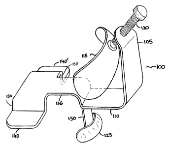
Referring to the drawings, the orthotic device 100 of the embodiment
illustrated
in Figure 1 incorporates an extraoral member 105 and an intraoral member 110
adapted
to fit inside the mouth of the patient. The members 105 and 110 are made from
stainless steel. Alternatively, such extraoral and intraoral members can be
made from a
rigid thermoplastic. Thermoplastic materials can be softened by heat to allow
for
manipulation of their shape, examples of suitable thermoplastic materials
include
acrylic, hard durometer, polypropylene, methyl vinyl acetate, ethyl vinyl
acetate,
polyethylene and hard durometer urethane.
A concave anterior maxillary abutment surface 115 is shown mounted to the
member 105 by a threaded bolt 120. As illustrated, the anterior maxillary
abutment
surface 115 is slightly angled towards the lip to provide more uniform contact
with the
tissue covering the subnasal maxillary bone. The anterior maxillary abutment
surface
115 is positioned such that it does not substantially impinge upon or obstruct
flow of air
through the nose.
In other embodiments of the invention, such an anterior maxillary abutment
surface may be adjustably mounted to the orthotic device by a slide
arrangement or any
other means known in the art. In yet, other embodiments, such an anterior
maxillary
abutment surface can be permanently affixed to the body of the orthotic.
CA 02635438 2008-07-07
WO 2006/072147 PCT/AU2006/000023
6
In the embodiment of the invention shown in Figure 1, the anterior maxillary
abutment surface 115 is made from an elastomeric material that is of a shape
to fit
comfortably upon the soft tissue and skin covering the subnasal maxillary
bone.
Examples of suitable thermoplastic materials include caprolactone,
polycaprolactone,
1,4-dibutanediol polyester, 2-oxepanone or silicone rubber.
The anterior mandibular abutment surface 125 of the embodiment of Figure 1 is
a convex band and is attached to member 110 by member .130. The anterior
mandibular abutment surface 125 pushes on the gingiva covering the mandible.
This
arrangement allows the orthotic device 100 to be applied to patients who have
lost one
or more of their anterior mandibular teeth. Further, by abutting the gingiva
covering
the mandible, the anterior mandibular abutment surface 125 avoids or minimizes
the
chance of mandibular teeth being undesirably relocated over time.
In the embodiment of the invention illustrated in Figure 1, the member 110
includes a deviation 135 to give the tongue sufficient room for the comfort of
the
patient. The intraoral posterior maxillary abutment surfaces 140 and 140' are
flat
projections which make contact with the maxillary surface.
The contact between the intraoral posterior maxillary abutment surfaces 140
and
140' and the maxillary surface helps resists rotation of the dental orthotic
device 100
produced by the interaction of the anterior mandibular abutment surface 125
and the
anterior maxillary abutment surface 115. The intraoral posterior maxillary
abutment
surfaces 140 and 140' are positioned such that they are unlikely to apply
sufficient
lateral force to the teeth to cause unwanted displacement of the teeth. The
intraoral
posterior maxillary abutment surfaces 140 and 140' are of a shape to
comfortably
conform to the patient's posterior maxillary characteristics. The two guide
surfaces 150
and 150' are positioned to make loose contact with the maxillary surfaces, in
other
embodiments, the intraoral posterior maxillary abutment surfaces may make
contact
with the maxillary molars or premolars, to position the orthotic device in the
mouth of
the patient.
The degree of protrusion or advancement of the mandible can depend upon
clinical requirements. The relative displacement of the mandible can be seen
to have
both side-to-side or forward-to-back components. Protrusion of the mandible
carries the
tongue forward so that (particularly in sleep) there is a reduced tendency for
the tongue
to impinge on the pharynx.
Referring to the second embodiment of the invention illustrated in Figure 2,
the
orthotic device 200 incorporates a concave anterior maxillary abutment surface
215
mounted via a threaded bolt 220 to the extraoral member 205. The intraoral
member
CA 02635438 2008-07-07
WO 2006/072147 PCT/AU2006/000023
7
210 has a member 230 and an anterior mandibular abutment surface 225. The
intraoral
posterior maxillary abutment surfaces 240 and 240' are flat projections. The
two guide
surfaces may be positioned to make loose contact with the maxillary surfaces
to resist
lateral movement of the orthotic device 200. In yet further embodiments, such
guide
surfaces make loose contact with the maxillary molars or premolars. In other
embodiments, the shape and configuration of such guide surfaces can be
adjusted to fit
the patient's requirements.
Referring to the third embodiment of the invention illustrated in Figure 3,
the
orthotic device 300 incorporates a concave anterior maxillary abutment surface
315
mounted via a threaded bolt 320 to the extraoral member 305. The intraoral
member
310 has a member 330, anterior mandibular abutment surface 325 and the two
intraoral
posterior maxillary abutment surfaces 340 and 340'. In this embodiment, the
guide
surfaces 350 and 350' are positioned to make loose contact with the maxillary
surface.
In other ernbodiments, such guide surfaces make contact with the maxillary
molars or
premolars to position and resist lateral movement of the orthotic device 300
in the
mouth of the patient. Member 310 further forms a hole into which the patient's
tongue
may extend.
Referring to the fourth embodiment of the invention illustrated in Figure 4,
the
orthotic device 400 incorporates a concave anterior maxillary abutment surface
415
mounted via a threaded bolt 420 to the extraoral member 405. The intraoral
member
410 has a member 430, anterior mandibular abutment surface 425 and the two
intraoral
posterior maxillary abutment surfaces 440 and 440'. In this embodiment, the
guide
surfaces 450 and 450' are connected by a member 460 which is raised in order
to give
the tongue sufficient room for the comfort of the patient.
Referring to the fifth embodiment of the invention illustrated in Figure 5,
the
orthotic device 500 incorporates a concave anterior maxillary abutment surface
515
mounted via a sliding arm 520 to the extraoral member 505. In this embodiment,
the
length of the arm is adjustable via the action of knob 560. In alternative
embodiments,
the knob may be substituted for another means for controlling the position of
the
concave anterior maxillary abutment surface. The other means may have facility
for
controlling the angle of an associated anterior maxillary abutment surface to
suit the
patient's needs and/or preference.
As illustrated, the length of the extraoral member 505 can be adjusted by the
extraoral adjustinent means 555. Alternatively, the length of such an
extraoral member
can be customized to the patient's needs when, for example, manufacturing the
orthotic.
CA 02635438 2008-07-07
WO 2006/072147 PCT/AU2006/000023
8
The extraoral member 505 is connected to the intraoral body portion 565 of the
orthotic device by member 510. The length of member 510 can be adjusted to
suit the
patient's requirement(s). In this embodiment, air holes 570 and 570' are shown
passing
through intraoral portion 565 are positioned to improve the flow of air
through and
around the orthotic device 500. The incorporation of this feature has
advantages for
patients with breathing difficulties who, for example, may have nasal
blockages or
congestion.
The anterior mandibular abutment surface 525 is connected to portion 565 by
members 530 and 530'. This variation gives the user's tongue more comfortable
stretch
space. In the illustrated embodiment, arms 530 and 530' are permanently
affixed to the
body portion 565. Alternatively, such anns may be adjustably mounted by a
slide
arrangement or other means known in the art.
As illustrated, the anterior mandibular abutment surface 525 is a convex band
and pushes on the gingiva covering the mandible. In alternative embodiments,
the
anterior mandibular abutment surface is appropriately shaped to make contact
with at
least a portion of the anterior mandibular surface.
The intraoral posterior maxillary abutment surfaces 540 and 540' are connected
to intraoral body portion 565 by arms 535 and 535'. This arrangement of arms
535 and
535' is advantageous in that it gives the user's tongue more room which may
improve
the comfort of the device. As illustrated, the abutinent surfaces 540 and 540'
are flat
projections which make contact with at least a portion of the maxillary
surface. This
contact resists rotation of the orthotic device 500 produced by the
interaction of the
mandibular abutment surface 525 and the anterior maxillary abutment surface
515.
Surfaces 540 and 540' are separated by soft palate abutment surface 550. In
the
illustrated embodiment, the surface is arch shaped to conform to or support
the patient's
soft palate. This arrangement is useful for patients whose soft palate can
potentially
collapse during sleep. By also supporting the soft palate, in some situations
the
effectiveness of the orthotic device may be improved.
Referring to the sixth embodiment of the invention illustrated in Figure 6,
the
orthotic device 600 incorporates a concave anterior maxillary abutment surface
615
mounted via a sliding arm 620 to the extraoral member 605. In this embodiment,
the
length of the arm is adjustable via the action of knob 660. As illustrated,
the length of
the extraoral member 605 can be adjusted by the extraoral adjustment means
655.
The extraoral member 605 is connected to the intraoral body portion 665 of the
orthotic device by member 610. In this embodiment, air holes 670 and 670'
passing
through intraoral body portion 665 are positioned to improve the flow of air
through
CA 02635438 2008-07-07
WO 2006/072147 PCT/AU2006/000023
9
and around the orthotic device. The convex band shaped anterior mandibular
abutment
surface 625 is connected to body portion 665 by members 630 and 630'.
The intraoral posterior maxillary abutment surfaces 640 and 640' are connected
to intraoral body portion 665 by arms 635 and 635'. The abutment surfaces 640
and
640' are flat projections which make contact with at least a portion of the
maxillary
surface. This contact resists rotation of the orthotic device 600 produced by
the
interaction of the mandibular abutment surface 625 and the anterior maxillary
abutment
surface 615.
Abutment surfaces 640 and 640' have guide surfaces 650 and 650' respectively,
which are positioned to make contact with the maxillary surfaces and help
position the
orthotic in the patient's mouth.
With this embodiment, there is no connecting member directly between the
abutment surfaces 640 and 640'. This arrangement has the advantage that the
user's
tongue has more comfortable stretch space and is particularly useful for
patients who
do not have problems with the soft palate collapsing during sleep.
Referring to the seventh embodiment of the invention illustrated in Figure 7A,
the orthotic device 700 incorporates a concave anterior maxillary abutment
surface 715
mounted via an adjustable arm 720 to the extraoral member 705. In this
embodiment,
the length of the arm 720 is adjustable via the action of knob 760. As
illustrated, the
length of the extraoral member 705 can be adjusted by the extraoral adjustment
means
755.
The extraoral member 705 is connected to the intraoral body portion 765 of the
orthotic device by member 710. The convex band shaped anterior mandibular
abutment surface 725 is connected to body portion 765 by members 730 and 730'.
The
body portion 765 may be adapted to comfortably conform to the user's anterior
maxillary and mandibular surfaces.
With the embodiment illustrated in Figure 7A, the body portion 765 has a
cavity
770. As shown in Figure 7B, which is a view of the body portion 765 from
direction A,
the opening of the cavity 775 is which is adapted to allow the tongue an
extended
stretch space and is adapted to hold the tongue in a protrusive position. This
arrangement advantageously improves the performance of the orthotic device in
some
patients.
The intraoral posterior maxillary abutment surfaces 740 and 740' are connected
to intraoral body portion 765 by arms 735 and 735'. The abutment surfaces 740
and
740' are flat projections which make contact with at least a portion of the
maxillary
surface. This contact resists rotation of the orthotic device 700 produced by
the
CA 02635438 2008-07-07
WO 2006/072147 PCT/AU2006/000023
interaction of the man4libular abutment surface 725 and the anterior maxillary
abutment
surface 715.
Abutment surfaces 740 and 740' have guide surfaces 750 and 750' respectively,
which are positioned to make contact with the maxillary surfaces and help
position the
5 orthotic in the patient's mouth.
With this embodiment, there is no connecting member directly between the
abutment surfaces 740 and 740'. This arrangement has the advantage that the
user's
tongue has more comfortable stretch space and is particularly useful for
patients who
do not have problems with the soft palate collapsing during sleep.
10 Referring to the eighth embodiment of the invention illustrated in Figure
8, the
orthotic device 800 incorporates a concave anterior maxillary abutment surface
815
mounted via a sliding arm 820 to the extraoral member 805. In this embodiment,
the
length of the arm 820 is adjustable via the action of knob 860. The length of
the
extraoral member 805 can be adjusted by the extraoral adjustment means 855.
The extraoral member 805 is connected to the intraoral body portion 865 of the
*
orthotic device by member 810. The convex band shaped anterior mandibular
abutment surface 825 is connected to body portion 865 by a single member 830.
The intraoral posterior maxillary abutment surfaces 840 and 840' are connected
to intraoral "body portion 865 by single arm 835 and by connecting arms 870
and 870'.
The length of arm 835 may be adjusted to suit the patient's requirements. The
abutment
surfaces 840 and 840' are flat projections which make contact with at least a
portion of
the maxillary surface. This contact resists rotation of the orthotic device
800 produced
by the interaction of the mandibular abutment surface 825 and the anterior
maxillary
abutinent surface 815.
Abutment surfaces 840 and 840' have guide surfaces 850 and 850' respectively,
which are positioned to make contact with the maxillary surfaces and help
position the
orthotic in the patient's mouth.
Attached to arm 835 is a posterior tail shaped portion 875 which is adapted to
depress the user's tongue during sleep. This has the advantage in some
patients of
improving the performance of the orthotic device for treating sleep apnoea.
Referring to the ninth embodiment of the invention illustrated in Figure 9,
the
orthotic device 900 incorporates an intraoral concave anterior maxillary
abutment
surface 915 mounted on intraoral member 905. While being intraoral, member 905
is
nevertheless extramaxillary as required by the invention, by being adapted for
positioning between the patient's top lip and maxillary. As illustrated, the
position of
the intraoral member 905 can be adjusted by the adjustment means 960.
CA 02635438 2008-07-07
WO 2006/072147 PCT/AU2006/000023
11
The intraoral member 905 is connected to the intraoral body portion 965 of the
orthotic device by member 910. The convex band shaped anterior mandibular
abutment surface 925 is connected to body portion 965 by members 930 and 930'.
The
position of the convex band shaped anterior mandibular abutment surface 925
can be
adjusted by movement of body portion 965 along member 910. The angle and/or
length of members 930 and 930' can also be adjusted to suit the user's
requirements.
As illustrated, an air hole 955 is shown passing through intraoral body
portion 965 and
is positioned to improve flow of air through and around the orthotic device.
The
incorporation of this feature has advantages for patients with breathing
difficulties who,
for example, may have nasal blockages or congestion.
The intraoral posterior maxillary abuthnent surfaces 940 and 940' are
connected
to intraoral body portion 965 by single ann 935 and by connecting arms 970 and
970'.
The length of arm 935 may be adjusted to suit the patient's requirements.
The abutment surfaces 940 and 940' are flat projections which make contact
with at least a portion of the maxillary surface. This contact resists
rotation of the
orthotic device 900 produced by the interaction of the mandibular abutment
surface 925
and the anterior maxillary abutment surface 915.
As illustrated, intraoral posterior maxillary abutment surfaces,940 and 940'
have
guide surfaces 950 and 950' respectively, which are positioned to make contact
with
the maxillary surfaces and help position the orthotic in the patient's mouth.
In
alternative embodiments, the guide surfaces are not need required.
Referring to the tenth embodiment of the invention illustrated in Figure 10A,
the
orthotic device 1000 incorporates a concave anterior maxillary abutment
surface 1015
mounted via an ann 1020 to the extraoral member 1005. In this embodiment, the
length of the arm 1020 is adjustable via the action of knob 1060.
Adjustability may
also be provided by a tumbuckle mechanism (or jack screw mechanism) which can
be
operated by a tumbuckle key to advance or retract such an arm as desired. In
this way,
the appropriate treatment can be provided as determined by a clinician.
In other einbodiments, the length of such an arm is fixed. As illustrated, the
length of the extraoral member 1005 can be adjusted by the extraoral
adjustment means
1055. Alternatively, the length of such an arm may be fixed.
The extraoral member 1005 is connected to intraoral arms 1035 and 1035' of the
orthotic device by members 1010 and 1010'. In this embodiment, the intraoral
body
portion 1065 is made from an elastic band and is adapted such that the user's
tongue
can slip into cavity 1070, but not easily slip out of it. The cavity is shown
in more
detail in Figure 10B along direction of arrow A. The combined biting forces
from the
CA 02635438 2008-07-07
WO 2006/072147 PCT/AU2006/000023
12
anterior maxillary and mandibular surfaces and/or elastic tension can securely
hold the
tongue in a forward position. This can improve the effectiveness of the
orthotic device
in some patients.
The intraoral posterior maxillary abutment surfaces 1040 and 1040' are
connected to intraoral arms 1035 and 1035'. The abutment surfaces 1040 and
1040' are
flat projections which make contact with at least a portion of the maxillary
surface.
The convex band shaped anterior mandibular abutinent surface 1025 is
connected to intraoral arms 1035 and 1035' by members 1030 and 1030'.
Abuhnent surfaces 1040 and 1040' have guide surfaces 1050 and 1050'
respectively, which are positioned to make contact with the maxillary surfaces
and help
position the orthotic in the patient's mouth.
Referring to the eleventh embodiment of the invention illustrated in Figure
11,
the orthotic device 1100 incorporates a concave anterior maxillary abutment
surface
1115 mounted to the extraoral member 1105. The intraoral member 1110 has a
positionally variable member 1130 and an attached anterior mandibular abutment
surface 1125. The relative position of the surface 1125 can be varied by the
action of
knob 1170 and thread 1160. In alternative embodiments, the position of such a
surface
can be controlled by other means known in the art. By movement of the member
1125,
the level of protrusion of the mandible can be controlled depending on the
needs of the
patient.
The intraoral posterior maxillary abutment surfaces 1140 and 1140' are flat
projections with two guide surfaces 1150 and 1150' positioned to make loose
contact
with the maxillary surfaces to resist lateral movement of the orthotic device
1100.
Referring to the twelfth embodiment of the invention illustrated in Figure 12,
the
orthotic device 1200 incorporates a concave anterior maxillary abutment
surface 1215
mounted via an arm 1220 to the extraoral member 1205. The length of the arm
1220 is
adjustable via the action of knob 1260. As illustrated, the length of the
extraoral
meinber 1205 can be adjusted by the extraoral adjustment means 1255.
The extraoral member 1205 is connected to the intraoral body portion 1265 of
the orthotic device by member 1210. The convex band shaped anterior mandibular
abutment surface 1225 is connected to arm 1235 by a single member 1230. The
length
of member 1230 may be adjusted by the action of means 1275 to suit the
patient's
requirement.
The intraoral posterior maxillary abutment surfaces 1240 and 1240' are
connected to intraoral body portion 1265 by single arm 1235 and by connecting
arm
1270. The length of arm 1235 may be adjusted to suit the patient's
requirements by the
CA 02635438 2008-07-07
WO 2006/072147 PCT/AU2006/000023
13
action of means 1280. Abutment surfaces 1240 and 1240' are flat projections
which
make contact with at least a portion of the maxillary surface and are attached
to ann
1235 by posterior arm 1270. Abutment surfaces 1240 and 1240' have guide
surfaces
1250 and 1250' respectively, which are positioned to make contact with the
maxillary
surfaces and help position the orthotic in the patient's mouth. The distance
between
surfaces 1240 and 1240' is variable via the action of means 1290.
Referring to the thirteenth embodiment of the invention illustrated in Figure
13,
the orthotic device 1300 incorporates an intraoral concave anterior maxillary
abutment
surface 1315 mounted on intraoral member 1305. As illustrated, the position of
the
intraoral member 1305 can be adjusted by the adjustment means 1360.
The intraoral member 1305 is connected to the intraoral body portion 1365 of
the orthotic device by member 1310. The convex band shaped anterior mandibular
abutment surface 1325 is connected to body portion 1365 by members 1330 and
1330'.
The position of the convex band shaped anterior mandibular abutment surface
1325 can
be adjusted by moveinent of body portion 1365 along member 910. The angle
and/or
length of members 1330 and 1330' can also be adjusted to suit the user's
requirements.
As illustrated, an air hole 1355 is shown passing through intraoral body
portion 1365
and is positioned to improve flow of air through and around the orthotic
device.
The intraoral posterior maxillary abutment surfaces 1340 and 1340' are
connected to intraoral body portion 1365 by single arm 1335 and by connecting
arms
1370 and 1370'. The length of arm 1335 and connecting arms 1370 and 1370' can
be
adjusted to suit the patient's requirements.
The abutment surfaces 1340 and 1340' are flat projections which make contact
with at least a portion of the maxillary surface. This contact resists
rotation of the
orthotic device 1300 produced by the interaction of the mandibular abutment
surface
1325 and the anterior maxillary abutment surface 1315.
Referring to the fourteenth embodiment of the invention illustrated in Figure
14,
the orthotic device 1400 incorporates a concave anterior maxillary abutment
surface
1415 mounted via a sliding arm 1420 to the extraoral member 1405. In this
embodiment, the length of the arm is adjustable via the action of adjustment
means
1460. As illustrated, the length of the extraoral member 1405 can be adjusted
by the
extraoral adjustment means 1455.
The extraoral member 1405 is connected to the intraoral body portion 1465 of
the orthotic device by member 1410. The convex band shaped anterior mandibular
abutment surface 1425 is connected to body portion 1465 by members 1430 and
1430'.
The position of the convex band shaped anterior mandibular abutment surface
1425 can
CA 02635438 2008-07-07
WO 2006/072147 PCT/AU2006/000023
14
be varied according to the user's requireiuents by movement of connecting web
portion
1490.
The intraoral posterior maxillary abutment surfaces 1440 and 1440' are
connected to intraoral body portion 1465 by arms 1435 and 1435'. The abutment
surfaces 1440 and 1440' make contact with at least a portion of the maxillary
surface.
This contact resists rotation of the orthotic device 1400 produced by the
interaction of
the mandibular abutment surface 1425 and the anterior maxillary abutment
surface
1415.
Abutment surfaces 1440 and 1440' have guide surfaces 1450 and 1450'
respectively, which are positioned to make contact with the maxillary surfaces
and help
position the orthotic in the patient's mouth.
With this einbodiment, there is a connecting member 1470 linking the abutment
surfaces 1440 and 1440'. This connecting member is adapted to contact and
depress
the user's tongue and has the advantage of improving the performance of the
orthotic
device for treating sleep apnoea in some patients. The position of connecting
member
1470 can be adjusted by the action of adjustment means 1480 and/or 1480'.
The orthotic device for retaining a patient's mandible in a protrusive
position
embodying the invention can have a number of beneficial uses, including as an
early
interceptive device to encourage mandibular growth, in the treatment of
certain
orthodontic problems, in the treatment of certain temporomandibular joint
problems, in
the management of bruxism, and/or in the treatment of snoring and obstructive
sleep
apnoea.
The orthotic device can be formed from orthodontic -materials such as acrylic,
cobalt chromium, gold, silver, platinum or other acceptable materials.
In some circumstances, it may be desirable to add a simple tooth-stabilising
plate, such as a retainer fitted to the orthotic device. This may serve to
resist movement
of the teeth due to engagement of the respective abutment surfaces, and also
may avoid
a degree of discomfort. The inclusion of such a plate may help to stabilize
the upper
and/or lower dentition.
It will be appreciated by persons skilled in the art that numerous variations
and/or modifications may be made to the invention as shown in the specific
embodiments without departing from the spirit or scope of the invention as
broadly
described. The present embodiments are, therefore, to be considered in all
respects as
illustrative and not restrictive.