Note: Descriptions are shown in the official language in which they were submitted.
CA 02636169 2008-08-11
VERTICAL FILLING-PACKAGING MACHINE AND METHOD OF
MANUFACTURINNG PACKAGING BAG
TECHNICAL FIELD
[0001] The present invention relates to a vertical filling-packaging
machine for manufacturing packaging backs in which a filler is sealed. The
present invention also relates to a method of manufacturing a packaging bag
in which a filler is sealed. This application is a division of co-pending
Canadian Patent Application No. 2,564,430 filed March 22, 2005.
BACKGROUND ART
[0002] Conventionally, vertical filling-packaging machines have been
used to package liquid or pasty fillers in bags (for example, see JP-A-95-
172403).
[0003] Fig. 1 is a diagram illustrating an example of conventional
vertical filling-packaging machines, which is shown in the foregoing document.
[0004] Vertical filling-packaging machine 101 forms a sheet-type film
161 into a cylindrical shape using back forming guide 105, and thermally seals
matching surfaces of the cylindrical film using vertically sealing mechanism
106. Then, a filler is introduced into thus formed cylindrical film 160 to
manufacture a packaging bag.
[0005] Vertical filling-packaging machine 101 comprises film feeding
rollers 107 for carrying cylindrical film 160 downward; introduction nozzle
108
for introducing a filler into cylindrical film 160; a pair of ironing rollers
125 for
squeezing cylindrical film 160 into a flat shape to form flat part 160a;
transverse sealing mechanism 130 for thermally sealing flat part 160a in a
width direction of cylindrical film 160; and cutting mechanism 140 which
contains cutter 141 for cutting the transversely sealed part which has been
thermally sealed by transverse sealing mechanism 130. The distance
between transverse sealing mechanism 130 and cutting device 140 in a
direction in which cylindrical film 160 is carried (vertical direction as
shown in
I
CA 02636169 2008-08-11
Fig. 1) is set to correspond to the length of one packaging bag to be
manufactured. In this connection, the thermal sealing operation by thermal
sealing mechanism 130 is also called "transverse sealing."
[0006] Exemplary operations of vertical filling-packaging machine 101
configured in this way will be described with reference to Fig. 2.
[0007] In a state illustrated in Fig. 2A, a pair of ironing rollers 125,
transverse sealing mechanism 130, and cutting mechanism 140 remain in an
open state. Also, one packaging bag 166 has already been formed below
cylindrical film 160. A filler is being continuously introduced into
cylindrical film
160 from introduction nozzle 108 (see Fig. 1).
[0008] Next, as illustrated in Fig. 2B, as the level of the filler exceeds
the position of ironing rollers 125, cylindrical film 160 is nipped by ironing
rollers 125 to divide the filler.
[0009] Next, as illustrated in Fig. 2C, ironing rollers 125 are driven to
rotate with cylindrical film 160 remaining nipped, thereby carrying
cylindrical
film 160 downward while forming flat part 160a in cylindrical film 160. This
carrying operation is continued until transversely sealed part 165, which has
been thermally sealed in the previous step, reaches a position at which it is
sandwiched by cutting mechanism 140.
[0010] Next, as illustrated in Fig. 2D, transverse sealing mechanism
130 and cutting mechanism 140 are driven while the carriage of cylindrical
film 160 is stopped. Transversely sealing mechanism 130 nips flat part 160a
formed by a pair of ironing rollers 125 to form transversely sealed part 165
in
the width direction of cylindrical film 160. Cutting mechanism 140, in turn,
nips
transversely sealed part 165 thermally sealed in the previous step to cool
transversely sealed part 165 in which heat still remains, and advances cutter
141 to cut transversely sealed part 165 in the width direction. In this way,
packaging bag 166 is cut off from cylindrical film 160.
2
CA 02636169 2008-08-11
[0011] Next, as illustrated in Fig. 2E, a pair of ironing rollers 125,
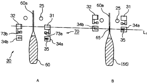
transverse sealing mechanism 130 and cutting mechanism 140 are all
brought into an open state. By opening cutting mechanism 140, the holding
state by cutting mechanism 140 is released to provide one packing bag 166.
[0012] Then, film feeding rollers 107 (see Fig. 1) are driven to again
carry cylindrical film 160 until the state shown in Fig. 2A appears. By
repeating a series of steps as described above, packing bags 166 filled with
the filler are manufactured in sequence.
[0013] After forming transversely sealed part 165 in cylindrical film 160
using transverse sealing mechanism 130 in this way, vertical filling-packing
machine 101 of Fig. 1 again carries cylindrical film 160 downward, and cools
and cuts transversely sealed part 165 by using cutting mechanism 140.
[0014] Japanese Patent No. 2598879 , for example, has proposed a
mechanism which is capable of fully performing operations for thermally
sealing, cooling and cutting cylindrical film 160 while the carriage of the
film is
stopped.
[0015] Fig. 3 is a diagram for describing the configuration and operation
of a conventional sealing and cutting mechanism proposed in Japanese
Patent No. 2598879.
[0016] As illustrated, transverse sealing and cutting mechanism 230
comprises heater bar 201 and heater bar receiver 204 for thermally sealing
flat part 160a of a cylindrical film in its width direction, and comprises
cooling
bar 202 and cufting device 205 for cooling and cutting a transversely sealed
part that is thermally sealed by heater bar 201 and heater bar receiver 204.
[0017] Heater bar 201 and cutting device 205 are driven by a power
source, for example, an air cylinder, and are configured to advance and
retract in directions perpendicular to flat part 160a. Cooling bar 202 and
heater bar receiver 204 in turn are pivotably supported by supporting shafts
3
CA 02636169 2008-08-11
210a, 210b, respectively, and are configured to pivotally move about
supporting shafts 210a, 210b in step with advancing and retracting
movements of heater bar 201 and cutting device 205, specifically, when
cooling bar 202 is not in contact with flat part 160a, as illustrated in Fig.
3A,
when heater bar 201 is advanced, and is in contact with flat part 160a, as
illustrated in Fig. 3B and when heater bar 201 is retracted. Heater bar
receiver
204 in turn is in contact with flat part 160a, as illustrated in Fig. 3A, when
cutting device 205 is retracted, and is not in contact with flat part 160a, as
illustrated in Fig. 3B, when cutting device 205 is advanced.
[0018] Transversely sealing and cutting mechanism 230 configured as
described above advances heater bar 201 and retracts cutting device 205, as
illustrated in Fig. 3A, to apply pressure and heat to flat part 160a by using
heater bar 201 and heater bar receiver 204, thereby thermally sealing flat
part
160a to form a transversely sealed part. Subsequently, as illustrated in Fig.
3B, heater bar 201 is retracted, and cutting device 205 is advanced to
sandwich flat part 160a between cufting device 205 and cooling bar 202 to
cool the transversely sealed part in which heat still remains. After this
cooling
operation has been performed for a predetermined time, cutter 203 provided
in cutting device 205 is advanced to cut the cooled transversely sealed part.
[0019] A vertical filling-packaging machine that uses such transverse
sealing and cutting mechanism 230 to manufacture packaging bags provides
the following advantages, since the thermal sealing, cooling, and cutting
operations can be fully carried out while the cylindrical film is stopped.
[0020] Vertical filling-packaging machine 101 shown in Fig. 1, after
performing a thermal sealing operation, again carries the cylindrical film
downward until transversely sealed part 165 formed thereby reaches the
height of cutting mechanism 140. Therefore, a large sealing width must be
used in consideration of variations in the amount of fed cylindrical film.
However, when transverse sealing and cutting mechanism 230 is used, the
sealing width can be reduced because such variations need not be taken into
consideration. A large sealing width means that extra cylindrical film is
used,
4
CA 02636169 2008-08-11
leading to an increase in the manufacturing cost of packing bags as products.
Next, since transverse sealing and cutting mechanism 230 need not carry the
cylindrical film downward as described above, and can therefore reduce the
time required for thermal sealing, cooling, and cutting operations, the
packing
bag manufacturing operation can therefore be performed at higher speeds
[0021] Other exemplary operations of vertical filling-packing machine
101 will be described with reference to Fig. 4.
[0022] First, as illustrated in Fig. 4A, a filler from introduction nozzle
108 is filled into cylindrical film 160, the lower end of which is thermally
sealed. As illustrated, the lower end of cylindrical film 160 is at a position
at
which a packaging bag manufactured in the preceding manufacturing step
was cut off, and is at the same height as the cutting edge of cutter 141.
Also,
area A, which is to be thermally sealed in a transverse sealing step, later
described, is positioned above ironing rollers 125.
[0023] Next, as illustrated in Fig. 4B, cylindrical film 160 is carried
downward until the level of the filler falls below ironing rollers 125.
[0024] Next, as illustrated in Fig. 4C, cylindrical film 160 is nipped by a
pair of ironing rollers 125 in an area above the level of the filler, and
ironing
roller 125 are driven to rotate. Consequently, the cylindrical film is carried
downward while flat part 160a is formed. This carrying operation is performed
until area A, which is to be thermally sealed, reaches the height of
transverse
sealing mechanism 130.
[0025] Subsequently, cylindrical film 160 is thermally sealed in its width
direction using thermal sealing mechanism 130, cylindrical film 160 is again
carried downward, and cylindrical film 160 is cut by using cutting mechanism
140, thereby manufacturing one packaging bag.
CA 02636169 2008-08-11
DISCLOSURE OF THE INVENTION
PROBLEMS TO BE SOLVED BY THE INVENTION
[0026] However, although the advantages as described above are
provided by using transverse sealing and cutting mechanism 230 as in Fig. 3,
the transverse sealing mechanism and cutting mechanism must be integrally
assembled into a single unit for this purpose. Since this requirement causes
limitations to the shape of heater bar 201 and cooling bar 202, difficulties
are
encountered, for example, in exchanging heater bar 201 with another type
one. In the manufacturing of packaging bags, heater bar 201 and cooling bar
202 must be interchanged that, in some cases, depends on the shape of
packaging bags to be manufactured and the material of the cylindrical film. It
is therefore desirable that the vertical filling-packaging machine be
configured
such that a variety of types of heater bars 201 and cooling bars 202 can be
mounted therein in view of the capabilities to manufacture a variety of types
of
packaging bags in different outline shapes.
[0027] On the other hand, the use of transverse sealing and cutting
mechanism 230 to fully perform thermal sealing, cooling, and cutting
operations without moving the cylindrical film can produce such effects as a
reduction in the sealing width and higher operation speeds, as described
above, so that it is preferable to have a vertical filling-packaging machine
capable of manufacturing such packaging bags.
[0028] It is therefore a first object of the present invention to propose a
vertical filling-packaging machine which is capable of satisfactorily forming
a
transversely sealed part by thermally sealing, cooling, and cutting a
cylindrical
film without moving the same, and is further capable of manufacturing a
variety of types of packaging bags in different outline shapes.
[0029) Incidentally, when the packing machine of Fig. 1 is operated
such that a pair of the ironing rollers nip an area of the cylindrical film in
which
the filler exists (see Fig. 2), the flat part, substantially free of the
filler, can be
relatively satisfactorily formed. However, as long as the ironing rollers nip
an
6
CA 02636169 2008-08-11
area in which the filler exists, it is difficult to completely remove the
filler from
the flat part. This is because some filler remains in the flat part due to the
capillary phenomenon.
[0030] On the other hand, when a pair of ironing rollers 125 are
operated to nip an area in which no filler exists, as illustrated in Fig. 4,
no filler
will remain in flat part 160a. However, when the filler is introduced into
cylindrical film 160 as illustrated in Fig. 4A, the filler can splash upward
and
stick to area A which is to be thermally sealed. This problem tends to arise
particularly when a filler having low viscosity is introduced, and when a
filler is
introduced at high speeds.
[0031] Even if the filler remains in area A which is to be thermally
sealed, the filler will not constitute an obstacle to the manufacturing of
packaging bags in many cases. However, when a filler contains, for example,
fine particulate solid matters, the solid matters are likely to be caught in
the
transversely sealed part, causing a degradation in quality of packaging bags
and causing defective transverse sealing.
[0032] Also, in the operation of Fig. 4, since a pair of ironing rollers 125
nip the cylindrical film above the level of the filler, air is trapped in the
manufactured packaging bag. When food or the like is packaged as a filler,
such trapped air causes the food to spoil, the trapped air should be
preferably
limited to the smallest possible amount.
[0033] It is therefore a second object of the present invention to
propose a vertical filling-packing machine and a method of manufacturing a
packaging bag, which are capable of preventing a filler from sticking to an
area which is to be transversely sealed, in order to satisfactorily form a
transversely sealed part. A further object is to propose a vertical filling-
packaging machine and a method of manufacturing a packaging bag, which
are capable of thus satisfactorily forming a transversely sealed part, and
further capable of minimizing air which is trapped in the packaging bag.
7
CA 02636169 2008-08-11
MEANS FOR SOLVING THE PROBLEM
[0034] To achieve the first object, a vertical filling-packaging machine of
the present invention comprises a pair of flat part forming rollers disposed
in
opposition to each other across a cylindrical film for rotating while
sandwiching the cylindrical film to carry the cylindrical film downward while
forming a flat part in the cylindrical film, a sealing mechanism including a
heater bar and a heater bar receiver for thermally sealing the flat part
formed
in the cylindrical film in a width direction thereof, a cutting mechanism
disposed below the sealing mechanism and including a pair of members for
cooling a thermally sealed part which has been thermally sealed by the
sealing mechanism, and a cutter for cutting the thermally sealed part, and a
driving mechanism for integrally holding the sealing mechanism and cutting
mechanism, and for integrally moving the sealing mechanism and cutting
mechanism along a direction in which the cylindrical film is carried.
[0035] According to the vertical filling-packaging machine of the present
invention thus configured, the sealing mechanism and cutting mechanism can
be moved along the direction in which the cylindrical film is carried using
the
driving mechanism. It is therefore possible to perform the thermal sealing,
cooling, and cutting operations without moving the cylindrical film.
Specifically,
after a thermally sealed part (transversely sealed part) has been formed in
the
cylindrical film using the sealing mechanism, the sealing mechanism and
cutting mechanism are moved using the driving mechanism. Subsequently,
control is conducted to cool and cut the thermally sealed part using the
cutting
mechanism. Also, since the sealing mechanism and cutting mechanism are
individually disposed independently of each other, the shape of the heater bar
and heater bar receiver as well as cooling members are not limited, as
compared with the conventional configuration which comprises them in a unit,
and as a result a variety of types can be used. Further, since the driving
mechanism integrally moves the sealing mechanism and cutting mechanism,
the configuration and operation control are simplified as compared with a
configuration which individually moves them.
[0036] Also, the vertical filling-packaging machine may further comprise
8
CA 02636169 2008-08-11
a tension applying mechanism for sandwiching both end portions of the
cylindrical film positioned below an area to be thermally sealed by the
sealing
mechanism to stretch the cylindrical film to the outer sides in the width
direction prior to a thermal sealing operation by the sealing mechanism. With
this mechanism, the part to be thermally sealed can be thermally sealed
without creases, thus making it possible to satisfactorily form the thermally
sealed part. Moreover, since the cylindrical film is nipped below the area to
be
thermally sealed when it is thermally sealed, the weight of the filler below
the
area to be thermally sealed is barely applied to the area that is to be
thermally
sealed. Accordingly, the area to be thermally sealed is prevented from
spreading.
[0037] The driving mechanism may comprise a supporter for integrally
supporting the sealing mechanism and cutting mechanism, a supporting shaft
for supporting the supporter for linear movement in a direction along the
direction in which the cylindrical film is carried, and a driving source for
moving the supporter along the supporting shaft. More specifically, the
driving
mechanism may comprise a ball screw for moving the supporter, and the
driving source may be a servo motor for rotating the ball screw. According to
the driving mechanism thus configured, the moving distance of the supporter
can be readily changed only by changing the electric signal applied to the
servo motor. Therefore, this is suitable for manufacturing a wide variety of
types of bags in different outline shapes. Also, since the driving source
comprises the ball screw and servo motor, the positioning of the supporter,
i.e., the positioning of the sealing mechanism and cutting mechanism, can be
accomplished with relatively high accuracy.
[0038] Also, the cutter may be disposed in a groove formed in one of
the pair of members, and may be configured to be capable of advancing and
retracting to and from the cylindrical film, and the other one of the pair of
members may be formed with a groove for the cutter to advance thereinto.
Also, the sealing mechanism may be configured such that, instead of the
heater bar and the heater bar receiver, another heater bar and another heater
bar receiver different in outline shape from the heater bar and the heater bar
9
CA 02636169 2008-08-11
receiver, respectively, can be attached to the sealing mechanism. Also, the
cutting mechanism may be configured such that, instead of the pair of
members, a pair of other members in outline shape different from the pair of
members, respectively, can be attached to the cutting mechanism.
[0039] To achieve the second object, a packaging bag manufacturing
method of the present invention is a packaging bag manufacturing method for
introducing a filler into a cylindrical film from the lower end of an
introduction
nozzle, and for thermally sealing the cylindrical film, into which the filler
has
been introduced, in a width direction thereof, thereby manufacturing a
packaging bag in which the filler is sealed. The method comprises the steps of
sandwiching the cylindrical film together with the lower end periphery of the
introduction nozzle by using a pair of members disposed in opposition to each
other across the cylindrical film, while an area of the cylindrical film to be
thermally sealed is positioned substantially above the pair of members,
introducing the filler from the lower end of the introduction nozzle while the
cylindrical film is nipped by the pair of members, carrying the cylindrical
film
until the area to be thermally sealed is positioned below the pair of members
after the introduction of the filler, and transversely sealing the area to be
thermally sealed in a width direction of the cylindrical film after carrying
the
cylindrical film.
[0040] The packaging bag manufacturing method of the present
invention includes sandwiching the cylindrical film together with the lower
end
periphery of the introduction nozzle by a pair of members, and introducing the
filler into the cylindrical film with the area to be thermally sealed being
positioned above the pair of members. Therefore, even if the filler splashes
within the cylindrical film during introduction of the filler, the filler will
not stick
to the area that is to be thermally sealed. The present packaging machine
subsequently carries the cylindrical film until the area that is to be
thermally
sealed is positioned below the pair of members, and transversely seals the
area to be thermally sealed and to which filler is prevented from sticking, to
manufacture a packaging bag. Since the present packaging machine
transversely seals the area which is prevented from the filler sticking
thereto,
CA 02636169 2008-08-11
the filler is hardly caught in the transversely sealed part, resulting in a
good
packaging bag which is less susceptible to defective sealing.
[0041] Also, the step in the manufacturing method of the present
invention that involves carrying the cylindrical film, may include sandwiching
an area of the cylindrical film above the level of the introduced filler and
below
the area to be thermally sealed by a pair of flat part forming rollers
disposed
below the pair of members in opposition to each other across the cylindrical
film, and carrying the cylindrical film downward while forming a flat part in
the
cylindrical film. In this way, the area of the cylindrical film to be
thermally
sealed can be thermally sealed after it has been squeezed into a flat shape.
Thus, the transversely sealed part can be prevented from creasing. Also, in
this event, since the pair of flat part forming rollers nip the cylindrical
film at an
intermediate position between the level of the introduced filler and the area
to
be thermally sealed, the introduced filler will not come into contact with the
area to be thermally sealed.
[0042] Also, the manufacturing method of the present invention may
further comprise the step of extruding air trapped in the cylindrical film
sandwiched by the pair of flat part forming rollers and thereby maintained
substantially in a sealed state prior to the thermal sealing step after the
cylindrical film has been carried while forming the flat part. When a pair of
flat
part forming rollers are driven to sandwich the cylindrical film above the
level
of the introduced filler, air is trapped in the cylindrical film. Therefore,
the step
of extruding the trapped air is provided, thereby minimizing the amount of air
included in the manufactured packaging bag.
[0043] Also, the manufacturing method of the present invention may
further comprise the step of cutting the thermally sealed part formed in the
thermal sealing step. In this way, the packaging bags are divided one by one.
Further, the manufacturing method of the present invention may further
comprise the step of stretching both end portions of the cylindrical film
positioned in the vicinity which is the vicinity of the area to be thermally
sealed, prior to the thermal sealing step. In this way, since creases and the
11
CA 02636169 2008-08-11
like are prevented from occurring near the area to be thermally sealed, the
transversely sealed part is more satisfactorily formed.
[0044] A vertical filling-packaging machine of the present invention
comprises a pair of flat part forming rollers disposed in opposition to each
other across a cylindrical film for rotating while sandwiching the cylindrical
film
to carry the cylindrical fiim downward while forming a flat part in the
cylindrical
film, a transverse sealing mechanism disposed below the pair of flat part
forming rollers for thermally sealing the flat part formed in the cylindrical
film in
a width direction thereof, a carrying mechanism for carrying the cylindrical
film
downward while the pair of flat part forming rollers are not sandwiching the
cylindrical film, an introduction nozzle disposed such that a lower end
thereof
is positioned above the pair of flat part forming rollers for introducing a
filler
into the cylindrical film from the lower end, and a liquid splash prevention
mechanism including a pair of members disposed in opposition to each other
across the cylindrical film for nipping the cylindrical film together with a
lower
end periphery of the introduction nozzle.
[0045] According to the vertical filling-packaging machine of the present
invention thus configured, the packaging bag manufacturing method of the
present invention can be used to manufacture a packaging bag having a
satisfactory transversely sealed part which will never have any trapped
filler.
[0046] The vertical filling-packaging machine of the present invention
may further comprise a deairing mechanism disposed below the transverse
sealing mechanism for extruding air trapped in the cylindrical film sandwiched
by the pair of flat part forming rollers and thereby maintained substantially
in a
sealed state prior to a thermal sealing operation by the transverse sealing
mechanism. Also, the vertical filling-packaging machine may further comprise
a cutting mechanism disposed below the transverse sealing mechanism for
cutting a thermally sealed part formed by the transverse sealing mechanism.
Also, the vertical filling-packaging machine may further comprise a tension
applying mechanism for sandwiching both end portions of the cylindrical film
positioned in the vicinity which is the vicinity of an area to be thermally
sealed
12
CA 02636169 2008-08-11
by the sealing mechanism to stretch the cylindrical film to the outer sides in
the width direction prior to a thermal sealing operation by the transverse
sealing mechanism.
[0047] It should be noted that the "liquid splash prevention mechanism"
prevents not only a liquid filler but also a pasty filler from splashing.
EFFECTS OF THE INVENTION
[0048] As described above, according to the vertical filling-packaging
machine of the present invention, since the sealing mechanism and cutting
mechanism can be moved along the direction in which the cylindrical film is
carried using the driving mechanism, it is possible to perform the thermal
sealing, cooling, and cutting operations without moving the cylindrical film.
Moreover, since the sealing mechanism and cutting mechanism are
individually provided independently of each other, the heater bar and heater
bar receiver as well as cooling members can be interchanged in various ways,
thus making it possible to manufacture a wide variety of packaging bags in
different outline shapes.
[0049] According to the method of manufacturing packaging bag and
the vertical filling-packaging machine of the present invention, the
cylindrical
film is sandwiched together with the introduction nozzle using a pair of
members of the liquid splash prevention mechanism, and the filler introducing
operation is performed with the area to be thermally sealed being positioned
above the pair of members, thereby preventing the filler from sticking to the
area to be thermally sealed during the introduction of the filler. By
thermally
sealing the area that is to be thermally sealed, to which filler is thereby
prevented from sticking in this way, it is possible to form a satisfactory
transversely sealed part which will never have any trapped filler.
[0050] Also, even when a pair of flat part forming rollers are driven to
sandwich the cylindrical film above the level of the introduced filler in
order to
prevent the introduced filler from coming into contact with the area to be
transversely sealed, air trapped in the packaging bag can be minimized by
13
CA 02636169 2008-08-11
extruding the air using the deairing mechanism.
[0051] The above and other objects, features, and advantages of the
present invention will become apparent from the following description with
reference to the accompanying drawings which illustrate an example of the
present invention.
BRIEF DESCRIPTION OF THE DRAWINGS
(0052] Fig. 1 is a diagram illustrating an example of conventional
vertical filling-packaging machines.
Figs. 2A-2E are diagrams illustrating an example of an operation
for manufacturing a packaging bag by the conventional vertical filling-
packaging machine of Fig. 1.
Figs. 3A and 3B are diagrams illustrating the configuration of a
conventional transverse sealing and cutting mechanism which performs all the
thermal sealing, cooling, and cutting operations without moving the
cylindrical
film.
Figs. 4A-4C are diagrams illustrating another example of an
operation for manufacturing a packaging bag by the conventional vertical
filling-packaging machine of Fig. 1.
Fig. 5 is a diagram schematically illustrating the configuration of
a vertical filling-packaging machine according to one embodiment of the
present invention.
Figs. 6A and 6B are cross-sectional views illustrating the valve
structure on a lower end side of an introduction nozzle.
Fig. 7 is a lateral view illustrating the configuration of a liquid
splash prevention mechanism.
Fig. 8 is a top plan view illustrating the configuration of the liquid
splash prevention mechanism.
Fig. 9 is a diagram for describing problems when flat part
forming rollers are not used.
Figs. 10A and 10B are diagrams for describing the configuration
and operation of a transverse sealing and cutting mechanism.
14
CA 02636169 2008-08-11
Fig. 11 is a diagram for describing the configuration of a
smoothing mechanism.
Fig. 12 is a diagram for describing the detailed configuration of
the transverse sealing and cutting mechanism, and the configuration of a
driving mechanism for moving the transverse sealing and cutting mechanism
up and down.
Figs. 13A and 13B are diagrams for describing the configuration
and operation of a deairing mechanism.
Figs. 14A-14C are diagrams for describing a packaging bag
manufacturing operation by the packaging machine of Fig. 5.
Figs. 15D-15F are diagrams for describing a packaging bag
manufacturing operation by the packaging machine of Fig. 5.
Figs. 16G-161 are diagrams for describing a packaging bag
manufacturing operation by the packaging machine of Fig. 5.
Figs. 17J-17L are diagrams for describing a packaging bag
manufacturing operation by the packaging machine of Fig. 5.
DESCRIPTION OF REFERENCE NUMERALS
[0053] 1 : Vertical Filling-Packaging Machine
6 : Vertical Sealing Mechanism
7: Film Feeding Belt
8 : Introduction Nozzle
8a : Introduction Nozzle Pipe
8b : Opening
8c : Control Valve
20 : Liquid Splash prevention mechanism
21 a, 21 b: Liquid Splash Prevention Bars
22a, 22b : Air Cylinders
23a, 23b : Covers
25: Flat Part Forming Roller
30 : Transverse Sealing and Cutting Mechanism
31 : Heater Bar
32 : Heater Bar Receiver
40 : Deairing Mechanism
CA 02636169 2008-08-11
41 : First Deairing Plate
42 : Second Deairing Plate
51 : Bag Holding Plate
51 a : Supporting Shaft
60 : Cylindrical Film
60a : Flat Part
60b : Side Edge Boundary
61 : Sheet-Type Film
65 : Transversely Sealed Part
66 : Packaging Bag
70 : Smoothing Mechanism
71 : Spring Hook
72 : Coupling Lever
73 : Tension Coil Spring
73a, 73b : Contact Members
75 : Supporting Shaft
76 : Mat
77 Stopper
81 : Supporter
82 : Ball Screw
85, 86 : Toggle Link
85a, 85b: Coupling Arms
85c: Rotating Shaft
85d : Rotating Lever
85e : Pulley
A: Area to Be Thermally Sealed
SM1, SM2, SM3 : Servo Motors
BEST MODE FOR CARRYING OUT THE INVENTION
[0054] In the following, embodiments of the present invention will be
described with reference to the drawings.
16
CA 02636169 2008-08-11
[0055] Fig. 5 is a diagram illustrating the configuration of vertical filling-
packaging machine 1 according to one embodiment of the present invention.
[0056] Vertical filling-packaging machine 1 comprises vertically sealing
mechanism 6 for thermally sealing the matching surfaces of sheet-type film 61
formed into a cylindrical shape by a bag forming guide, not shown, in a
longitudinal direction to form cylindrical film 60; film feeding belt 7 for
carrying
cylindrical film 60 downward; introduction nozzle 8 for introducing filler
into
cylindrical film 60; liquid splash prevention mechanism 20 driven when the
filler is introduced from introduction nozzle 8; a pair of flat part forming
rollers
25 for squeezing cylindrical film 60 into a flat shape to form flat part 60a;
transverse sealing and cutting mechanism 30 for transversely sealing flat part
60a and cutting the transversely sealed part to tear off a packaging bag;
deairing mechanism 40 for extruding air trapped in cylindrical film 60 into
which the filler has been introduced; and bag holding plate 51 for holding the
bottom of cylindrical film 60 when deairing mechanism 40 is driven.
[0057] It should be noted that vertically sealing mechanism 6 and film
feeding belt 7 are typical ones used in this type of vertical packaging
machine,
so that a detailed description thereon is omitted.
[0058] Introduction nozzle 8 is provided for introducing a liquid or pasty
filler into cylindrical film 60, and is disposed within a carrying path of
cylindrical film 60. The lower end of introduction nozzle 8 is substantially
at
the same level as liquid splash prevention mechanism 20. In this way, the
lower end of introduction nozzle 8 can be nipped by liquid splash prevention
bars 21 a, 21 b of liquid splash prevention mechanism 20, as will be later
described. In this connection, introduction nozzle 8 is disposed to be coaxial
with cylindrical film 60 which has a substantially cylindrical cross-sectional
shape, such that the filler can be uniformly introduced into cylindrical film
60.
[0059] Introduction nozzle 8 of this embodiment intermittently
introduces the filler, and has a valve structure on its lower end side, as
illustrated in Fig. 6. Control valve 8c is vertically movably arranged in
17
CA 02636169 2008-08-11
introduction nozzle pipe 8a for transporting the filler. By moving control
valve
8c to open/close opening 8b of introduction nozzle pipe 8a, the filler
introducing operation is controlled.
[0060] Fig. 7 is a lateral view illustrating the configuration of liquid
splash prevention mechanism 20, and Fig. 8 is a top plan view illustrating the
configuration of the same liquid splash prevention mechanism 20.
[0061] Liquid splash prevention mechanism 20 has a pair of liquid
splash prevention bars 21 a, 21 b which are disposed in opposition to each
other across the carrying path of cylindrical film 60, as illustrated in Figs.
7
and 8.
[0062] Liquid splash prevention bar 21 a, 21 b is formed with cover 23a,
23b near the center thereof, and cover 23a, 23b are flat on both sides. Covers
23a, 23b are shaped so as to surround introduction nozzle 8 along the
periphery of introduction nozzle 8. More specifically, liquid splash
prevention
bars 21 a, 21 b are formed to define a constant distance to the periphery of
introduction nozzle 8 when it is advanced.
[0063] Each liquid splash prevention bar 21 a, 21 b is attached to the
leading end of an arm of air cylinders 22a, 22b, respectively. In this way, by
driving air cylinders 22a, 22b, liquid splash prevention bars 21 a, 21 b move
in
directions perpendicular to the direction in which cylindrical film 60 is
carried
(horizontal direction as shown in Fig. 5), to take a position that is
indicated by
a solid line and a position that is indicated by a one-dot chain line.
[0064] Liquid splash prevention mechanism 20 thus configured uses
liquid splash prevention bars 21 a, 21 b as an advanced position when the
filler
is introduced into cylindrical film 60 from introduction nozzle 8. As liquid
splash prevention bars 21 a, 21 b are advanced, cylindrical film 60 is
sandwiched between liquid splash prevention bars 21 a, 21 b and between
the outer periphery of introduction nozzle 8 and each liquid splash prevention
bar 21 a, 21 b and is thereby substantially sealed. In this event, since
opening
18
CA 02636169 2008-08-11
8b at the lower end of introduction nozzle 8 opens into cylindrical film 60 in
the
substantially sealed state, there is no interference with the filler
introducing
operation.
[0065] The filler introducing operation of vertical filling-packaging
machine 1 of this embodiment is performed during the period when an area to
be thermally sealed is positioned above liquid splash prevention bars 21 a, 21
b, as will be later described. Therefore, even if the filler splashes during
the
introducing operation, the filler will not splash to the area to be thermally
sealed because cylindrical film 60 is sandwiched by liquid splash prevention
mechanism so that it remains substantially sealed.
[0066] In a conventional packaging machine which is not equipped with
such mechanism 20, when filler with low viscosity, which is more likely to be
splashed, is introduced, by way of example, the filler must be introduced at
lower introduction speeds. However, since liquid splash prevention
mechanism 20 is provided, this embodiment is free from the problem in which
filler sticks to an area to be thermally sealed even if the filler is
introduced at
high speeds. It is therefore possible to perform the introducing operation at
higher speeds, resulting in a reduction in cycle time for manufacturing a
single
packaging bag.
[0067] Flat part forming rollers 25 are disposed in opposition to each
other across the carrying path of cylindrical film 60 below the lower end of
introduction nozzle 8. Flat part forming rollers 25 are configured in a manner
similar to ironing rollers typically used in this type of packaging machine,
and
rotate with cylindrical film 60 nipped therebetween. In this way, cylindrical
film
60 is squeezed to form flat part 60a. Accordingly, flat part forming rollers
25
preferably have a length such that they can squeeze cylindrical film 60 over
the entire width thereof. Flat part forming rollers 25 are disposed such that
they can be advanced and retracted by a driving source, not shown, in
directions perpendicular to the direction in which cylindrical film 60 is
carried.
Also, flat part forming rollers 25 are configured to be driven by another
similar
driving source, not shown, to rotate themselves. In this connection, flat part
19
CA 02636169 2008-08-11
forming rollers 25 are driven to rotate in synchronization with film feeding
belt
7.
[0068] Flat part forming rollers 25 thus configured are used to divide
the filler introduced into cylindrical film 60, and are used to nip
cylindrical film
60 above the level of the introduced filler.
[0069] As flat part forming rollers 25 are driven to rotate with cylindrical
film 60 sandwiched therebetween, cylindrical film 60 is carried downward
while flat part 60a is formed. Flat part 60a is an area in which cylindrical
film is
transversely sealed in a subsequent step. When flat part 60a is transversely
sealed in this way, the transversely sealed part is less susceptible to
creases.
[0070] Flat part forming rollers 25 also have a function of squeezing
cylindrical film 60 to put folds on the edges of both sides. If cylindrical
film 60
is thermally sealed without putting the folds on the edges of the sides, side
edge boundary part 60b, shown in Fig. 9, can be broken depending on the
condition of cylindrical film 60. Therefore, the folds put on cylindrical film
60,
like those in this embodiment, are preferable in view of the ability to
prevent
the film, which is susceptible to the problems as mentioned above, from being
broken when it is transversely sealed.
[0071] Transverse sealing and cutting mechanism 30 comprises heater
bar 31 and heater bar receiver 32 for transverse sealing operation; smoothing
mechanism 70 disposed beneath them; and a pair of cooling bars 34a, 34b for
cooling and cutting a transversely sealed part, as illustrated in Fig. 10.
Also,
cutter 35 is provided in cooling bar 34a for cutting cylindrical film 60.
[0072] Heater bar 31 and heater bar receiver 32 are disposed in
opposition to each other across the carrying path of cylindrical film 60, and
are
respectively configured for movement in the direction perpendicular to the
direction in which cylindrical film 60 is carried. Heater bar 31 and heater
bar
receiver 32 are driven by a driving source, later described with reference to
Fig. 12, and can nip cylindrical film 60 therebetween.
CA 02636169 2008-08-11
[0073] Heater bar 31 contains a heater (not shown) for heating
cylindrical film 60. On the other hand, silicone rubber is adhered on a
surface
opposite to heater bar 31 of heater bar receiver 32. Flat part 60a of
cylindrical
film 60 is sandwiched, pressurized, and heated by heater bar 31 and heater
bar receiver 32 to form transversely sealed part 65 over the entire width of
cylindrical film 60.
[0074] Smoothing mechanism 70 will be described with reference to
Fig. 11. Fig. 11 is a diagram of heater bar 31 and heater bar receiver 32 as
viewed from below. In this connection, since smoothing mechanism 70 is
similar in configuration to that disclosed in JP-A-2002-234504 which was
previously filed by the present applicant, a detailed description thereon is
omitted.
[0075] Smoothing mechanism 70 comprises one pair each of contact
members 73a, 73b which come into contact with cylindrical film 60, which has
been squeezed into a flat shape by flat part forming rollers 25, to stretch
the
film toward both sides (see outlined arrows). Mat 76 made of an elastic
material such as rubber is adhered on a front surface of each contact member
73a, 73b such that cylindrical film 60 can be stretched. A material that is
selected for mat 76 does not exert excessive frictional force on cylindrical
film
60 such that this would cause cylindrical film 60 to spread when sandwiched
cylindrical film 60 is stretched in the directions of the arrows.
[0076] Since each contact member 73a, 73b is attached in a similar
structure, one contact member 73a will be described below as a
representative example. Contact member 73a is pivotably supported by one
end of coupling lever 72, and the opposite end of coupling lever 72 is
pivotably supported by supporting shaft 75. Therefore, as coupling lever 72 is
pivoted about supporting shaft 75, contact member 73a pivotally moves in a
direction indicated by an arrow. Also, tension coil spring 74 hooked on spring
hook 71 has the other end hooked at the leading end of coupling lever 72. By
the action of tension coil spring 74 and stopper 77, contact member 73a is
21
CA 02636169 2008-08-11
positioned closer to cylindrical film 60 than other structure components, as
illustrated, in the initial state of smoothing structure 70.
[0077] Smoothing mechanism 70 thus configured operates when
heater bar 31 and heater bar receiver 32 are advanced. Specifically, as heater
bar 31 and heater bar receiver 32 are advanced toward cylindrical film 60,
contact members 73a, 37b, which are opposite each other, sandwich both
end sides of cylindrical film 60 therebetween before heater bar 31 and heater
bar receiver 32 come into contact with cylindrical film 60. As heater bar 31
and heater bar receiver 32 are further advanced in this state, contact
members 73a, 73b move toward the outer sides of cylindrical film 60,
respectively, while they rub against cylindrical film 60. Thus, cylindrical
film 60
is held while creases are removed by contact members 73a, 73b.
Consequently, cylindrical film 60 is satisfactorily subjected to pressure and
heated by heater bar 31 and heater bar receiver 32.
[0078] As described above, contact members 73a, 73b of smoothing
mechanism 70 sandwich cylindrical film 60 below an area to be thermally
sealed (below heater bar 31) during the thermal sealing operation, so that the
load that is applied to the thermally sealed part by the filler becomes
lighter
until the thermal sealing operation is completed. Thus, the thermally sealed
part is prevented from spreading due to the weight of the filler.
[0079] Cooling bars 34a, 34b are disposed below smoothing
mechanism 70, as illustrated in Fig. 10, and they are driven by a driving
source, later described with reference to Fig. 12, to nip transversely sealed
part 65 of cylindrical film 60 therebetween. Also, since cooling bars 34a, 34b
thermally transmit heat of thermally sealed part 65 to these members to cool
transversely sealed part 65, they are preferably made of a material having
high thermal conductivity.
[0080] One cooling bar 34a is provided with cutter 35 in a groove
formed in cooling bar 34a for cutting transversely sealed part 65 to separate
packaging bag 66 from cylindrical film 60. Cutter 35 is movably configured to
22
CA 02636169 2008-08-11
advance to and to retract from cylindrical film 60 by a driving source, not
shown. Opposite cooling bar 34b is formed with a groove for receiving cutter
35 when it advances for a cutting operation.
[0081] In this connection, heater bar 31 and heater bar receiver 32 as
well as a pair of cooling bars 34a, 34b are all configured to be
interchangeable with those of other types having outline shapes different from
them. In conventional transverse sealing and cutting mechanism 230 as
illustrated in Fig. 3, the integrated mechanism must be entirely interchanged
in order to manufacture, for example, packaging bags having different shapes.
However, transverse sealing and cutting mechanism 30 of this embodiment
facilitates an exchanging operation because only heater bar 31 and cooiing
bars 34a, 34b need be interchanged with those of different types. Also, since
a plurality of integrated mechanisms need not be provided in accordance with
the shapes of packaging bags, the facility cost can be restrained.
[0082] Foregoing heater bar 31 and heater bar receiver 32, smoothing
mechanism 70, and a pair of cooling bars 34a, 34b are integrally held by a
supporter (see Fig. 12), later described, and integrally move in a vertical
direction along the carrying path of cylindrical film 60. The position shown
in
Fig. 10A indicates the lower end position of their movable range, while the
position shown in Fig. 10B indicates the upper end position.
[0083] At the lower end position in Fig. 10A, heater bar 31 and heater
bar receiver 32 are positioned at the same height as packaging bag cutting
position L1. The thermal heating is performed by driving heater bar 31 and
heater bar receiver 32 in this state. On the other hand, at the upper end
position in Fig. 10B, transverse sealing and cutting mechanism 30 has entirely
moved upward to take a position at the same height as packaging bag cutting
position L1. Transversely sealed part 65 is cooled and cut by driving cooling
bars 34a, 34b and cutter 35 in this state. In this connection, "packaging bag
cutting position L1" indicates a position at which cylindrical film 60 is cut
off by
cutter 35, and is set at the center of transversely sealed part 65 in the
direction in which cylindrical film 60 is carried.
23
CA 02636169 2008-08-11
[0084] Referring to Fig. 12, a description will be given of the detailed
configuration of transverse sealing and cutting mechanism 30 and the
configuration of driving mechanism 80 for moving transverse sealing and
cutting mechanism 30 up and down. For simplifying the description,
smoothing mechanism 70 is omitted from the illustration of Fig. 12.
[0085] Heater bar 31 and heater bar receiver 32 as well as a pair of
cooling bars 34a, 34b are all configured to be driven by servo motors SM1,
SM2, such that their power is transmitted through toggle links 85, 86. In the
following, a mechanism for opening and closing heater bar 31 and heater bar
receiver 32 will be described as a representative example.
[0086] Toggle link 85 is a link mechanism for converting rotational
motions of servo motor SM1 to motions for opening and closing heater bar 31
and heater bar receiver 32. The power of servo motor SM1 is transmitted to
rotating shaft 85c through a belt stretched between the output shaft of servo
motor SM1 and pulley 85e. Rotating lever 85d is fixed to rotating shaft 85c.
One end of this rotating lever 85d and heater bar 31 are coupled by coupling
arm 85b, while the opposite end of rotating lever 85d and heater bar receiver
32 are coupled by coupling arm 85a. In toggle link 85, when heater bar 31 is
in abutment to heater bar receiver 32, coupling arms 85a, 85b and rotating
lever 85d are all in a horizontal state. In this way, even if horizontal
loads, that
are attempting to open heater bar 31 and heater bar receiver 32, are applied
to heater bar 31 and heater bar receiver 32, respectively, the loads are
unlikely to be converted to rotational motions of rotating lever 85d.
Therefore,
heater bar 31 and heater bar receiver 32 are allowed to stably pressurize
cylindrical film 60. Such a link mechanism is also advantageous in that servo
motor SM1 is required to generate a small amount of power.
[0087] Driving mechanism 80 for moving transverse sealing and cutting
mechanism 30 up and down comprises supporter 81 for holding transverse
sealing and cutting mechanism 30; ball screw 82 for moving supporter 81 up
and down; and servo motor SM3 which is a driving source for rotating ball
24
CA 02636169 2008-08-11
screw 82.
[0088] Supporter 81 integrally holds heater bar 31 and heater bar
receiver 32, a pair of cooling members 34a, 34b, respective toggle links 85,
86 for opening and closing them, and servo motors SM1, SM2. Supporter 81
is vertically movably arranged along guide members which comprise, for
example, two supporting shafts (not shown) disposed in parallel to each other
with ball screw 82 interposed therebetween.
[0089] Ball screw 92 is assembled to be engaged in an engaging hole
formed in supporter 81. Belt 83 is stretched between the lower end of ball
screw 82 and the output shaft of servo motor SM3 for transmitting the power
of servo motor SM3.
[0090] Driving mechanism 80 thus configured applies servo motor SM3
with a predetermined electric signal from a controller, not shown, to rotate
servo motor SM3 by a predetermined amount, causing ball screw 82 to rotate
in association therewith. In this way, heater bar 81, heater bar receiver 32,
cooling bars 34a, 34b, and the like are integrally moved up and down and
positioned at predetermined positions. The distance that is moved in this
event can be changed only by changing the electric signal applied to servo
motor SM3 from the controller. In addition, driving mechanism 80, which is
composed of ball screw 82 and servo motor SM 1, can relatively accurately
position heater bar 81, heater bar receiver 32, cooling bars 34a, 34b, and the
like.
[0091] When comparing the configuration for moving transverse sealing
and cutting mechanism 30 relative to stationary cylindrical film 60, as in
this
embodiment, with the conventional configuration illustrated in Fig. 3, the
configuration of this embodiment suffers from a degradation in positional
accuracy due to transverse sealing and cutting mechanism 30 which is moved
up and down using driving mechanism 80. However, in comparison with the
conventional configuration for moving cylindrical film 60, as illustrated in
Fig.
15, the configuration of this embodiment can accomplish the positioning with a
CA 02636169 2008-08-11
higher positional accuracy.
[0092] The reason for the above will be described below. In the
configuration as shown in Fig. 15, cylindrical film 60 is generally carried by
film feeding belt 7 (see Fig. 1) provided in the form of a belt conveyer, film
feeding rollers 107 (see Fig. 1) provided in the form of a pair of rotatable
rollers, and the like. In this event, cylindrical film 60 is susceptible to
variations
in the amount of feed. On the other hand, in the configuration of Fig. 2 for
moving cylindrical film 60, cylindrical film 60 must be again moved downward
to the height of cooling bars 34a, 34b after it has been thermally sealed. In
this way, in the configuration for intermittently and downwardly carrying
cylindrical film 60 into which a filler has been introduced, the weight of the
introduced filler is applied to cylindrical film 60 as an impact force, so
that
cylindrical film 60 can slightly spread in some cases. This spreading can vary
the distance that cylindrical film 60 is carried. In particular, transversely
sealed
part 65, which has not been completely cooled, is susceptible to such
spreading.
[0093] In contrast, in the configuration for stopping the carriage of
cylindrical film 60 and for moving transverse sealing and cutting mechanism
30, as in this embodiment, though misregistration is caused by moving
transverse sealing and cutting mechanism 30 itself, this misregistration is
attributable to the mechanical structure of driving mechanism 80 for moving
transverse sealing and cutting mechanism 30 up and down, so that the
amount of misregistration is small as compared with the configuration for
moving cylindrical film 60. Further, in this embodiment, since cylindrical
film
60 need not be intermittently carried, cylindrical film 60 is less likely to
spread
due to the weight of the filler. In particular, transversely sealed part 65,
not
cooled, and is less likely to spread or deform.
[0094] Next, comparisons will be made among the configuration of this
embodiment, the conventional configuration illustrated in Fig. 3, and the
conventional configuration illustrated in Fig. 15 in regard to the time
required
from thermal sealing to cutting. Drawing a comparison between the
26
CA 02636169 2008-08-11
configuration of this embodiment and the configuration of Fig. 3, the
configuration of this embodiment requires a longer amount of time till the
cutting by the time required to move transverse sealing and cutting
mechanism 30 up and down, but the time is reduced in comparison with the
configuration of Fig. 15. This is because the configuration for carrying
cylindrical film 60 downward, as in the configuration of Fig. 15, experiences
difficulties in carrying cylindrical film 60 at a certain predetermined speed
or
higher, for example, for reducing an impact force applied to cylindrical film
60.
[0095] The following control may be implemented in order to increase
the speed of packaging bag manufacturing operations. In Fig. 10, the distance
between cooling bars 34a, 34b is the same as the distance between heater
bar 31 and heater bar receiver 32, but the distance between cooling bars 34a,
34b may be set shorter. At the upper end position of transverse sealing and
cutting mechanism 30, heater bar 31 and heater bar receiver 32 are
substantially at the same height as flat part forming rollers 25. It is
therefore
necessary to ensure a longer distance between heater bar 31 and heater bar
receiver 32 than the distance between flat part forming rollers 25 such that
heater bar 31 and heater bar receiver 32 do not interfere with flat part
forming
rollers 25. On the other hand, since cooling bars 34a, 34b will not interfere
with flat part forming rollers 25, the distance between cooling bars 34a, 34b
can be reduced. This results in a shorter distance over which cooling bars
34a, 34b move, thus making it possible to drive them at higher speeds. In this
connection, the distance between cooling bars 34a, 34b may be adjusted only
by changing the electric signal applied to servo motor SM2 shown in Fig. 12.
[0096] Deairing mechanism 40 and bag holding plate 51 will be
described below with reference to Fig. 13. It should be noted that Fig. 13
illustrates only flat part forming rollers 25 but does not illustrate
transverse
sealing and cutting mechanism 30 disposed between flat part forming rollers
25 and deairing mechanism 40.
[0097] Bag holding plate 51 is a member for holding the bottom of
cylindrical film 60 into which a filler has been introduced, and comprises a
27
CA 02636169 2008-08-11
tabular member. Bag holding plate 51 has one end side pivotably supported
by supporting shaft 51 a, and is configured to have a horizontal state,
indicated
by a solid line in Fig. 13B, and an inclined state, indicated by a one-dot
chain
line, by means of a driving source, not shown. The horizontal state of bag
holding plate 51 is taken when deairing mechanism 40 performs a deairing
operation, later described, and when transverse sealing and cutting
mechanism 30 transversely seals and cuts cylindrical film 60 after the
deairing
operation. On the other hand, the inclined state is selected in order to drop
one packaging bag 66 that is held on bag holding plate 51. In this connection,
a belt conveyer (not shown), for example, is disposed below bag holding plate
51 a, such that packaging bag 66 is carried to a container, not shown.
[0098] Deairing mechanism 40 comprises first deairing plates 41 a, 41
b and second deairing plates 42a, 42b which are disposed opposite to each
other across the carrying path of cylindrical film 60. Any of the deairing
plates
is arranged movably in direction perpendicular to the direction in which the
cylindrical film is carried, and a driving source for first deairing plates 41
a, 41
b is provided independently of a driving source for second deairing plates
42a,
42b. In this way, first deairing plates 41 a, 41 b and second deairing plates
42a, 42b can be driven independently of each other.
[0099] Second deairing plates 42a, 42b are members for pressing
cylindrical film 60, into which filler has been introduced, from both sides to
extrude air within cylindrical film 60. Then, they are formed in a size that
corresponds to the size of packaging bag 66 such that they can favourably
perform their pressing operation. On the other hand, first deairing plates 41
a,
41 b are members for preventing the filler within cylindrical film 60 from
being
pushed upward during the deairing operation, and are disposed above second
deairing plates 42a, 42b.
[0100] A description will be given of the operation of deairing
mechanism 40 thus configured.
[0101] First, first deairing plates 41 a, 41 b are brought closer to each
28
CA 02636169 2008-08-11
other with the interposition of a gap therebetween wide enough to allow air
within cylindrical film 60 to escape upward. Next, as second deairing plates
42a, 42b are advanced in directions in which they approach each other,
cylindrical film 60 having filler introduced thereinto is pressed from both
sides,
and in association therewith, air within cylindrical film 60 is extruded
upward
from an area in which cylindrical film 60 is sandwiched by first deairing
plates
41 a, 41 b to extract the air from cylindrical film 60.
[0102] In this connection, second deairing plates 42a, 42b are
preferably arranged in such a manner that their moving distances are
adjustable in order that the air within cylindrical film 60 can be favorably
extruded in this deairing operation. In this way, the deairing operation can
be
performed to minimize the amount of air within cylindrical film 60 by
adjusting
the moving distances of second deairing plates 42a, 42b as appropriate in
accordance with the size of packaging bag 66 and the amount of filler. In
addition, first deairing plates 41 a, 41 b may be brought closer to each other
to
such an extent that the filler is extruded upward with difficulty, even within
a
range in which the air can be smoothly extruded. Nevertheless, even if the
filler is extruded beyond first deairing plates 41 a, 41 b, the transverse
sealing
operation will not be adversely affected unless the level of the filler
reaches
area A that is to be thermally sealed, as shown in Fig. 13B.
[0103] Referring to Figs. 14 to 17, a description will be given below of
packaging bag manufacturing operations of vertical filling-packaging machine
1 of this embodiment configured as described above.
[0104] In an initial state illustrated in Fig. 14A, one packaging bag has
been manufactured in the preceding manufacturing step, and the thermally
sealed lower end of cylindrical film 60 lies at packaging bag cutting position
L1. Liquid splash prevention mechanism 20 in turn is in a closed state.
Cylindrical film 60 is sandwiched by liquid splash prevention bars 21 a, 21 b
substantially into a flat shape, and is substantially in a sealed state.
However,
cylindrical film 60 is not completely flat, but an area sandwiched by
introduction nozzle 8 and liquid splash prevention bars 21 a, 21 b bulges
29
CA 02636169 2008-08-11
along the periphery of introduction nozzle 8. Flat part forming rollers 25,
transverse sealing and cutting mechanism 30 and deairing mechanism 40 arc
all set in an open state, while bag holding plate 51 is placed in a horizontal
state. Transverse sealing and cutting mechanism 30 is positioned at the lower
end of its movable range, and heater bar 31 and heater bar receiver 32 are
positioned at the same height as packaging bag cutting position L1. Area A,
which is to be thermally sealed in a transverse sealing step, later described,
is
positioned above liquid splash prevention mechanism 20.
[0105] Next, as illustrated in Fig. 14B, the introduction of a filler is
started from introduction nozzle 8 with liquid splash prevention mechanism 20
maintained in a closed state. The filler will not stick to area A that is to
be
thermally sealed because cylindrical film 60 is sandwiched by liquid splash
prevention mechanism 20.
[0106] Next, as illustrated in Fig. 14C, the introducing operation is
continued until the introduced filler reaches the amount for a single bag to
be
sealed in packaging bag 66 (see Fig. 17). Liquid splash prevention
mechanism 20 is switched to an open state in the middle of this introducing
operation. In this connection, the introducing operation may be once stopped
when liquid splash prevention mechanism 20 is opened, or may be continued
as is.
[0107] Liquid splash prevention mechanism 20 is opened in the middle
of the introducing operation with the intention of allowing air within
cylindrical
film 60 to escape to the outside. As described above, cylindrical film 60
remains substantially sealed while liquid splash prevention mechanism 20 is
closed. Therefore, if one attempts to introduce an amount of the filler for
one
bag as it is, air within the cylindrical film cannot escape, with the result
that
pressure becomes higher within cylindrical film 60 as more and more filler is
introduced. When pressure is applied to cylindrical film 60 in this way,
cylindrical film 60 can bulge and become deformed, or the thermally sealed
part can break at the lower end of cylindrical film 60. Also, the air that is
under
high pressure as a result of the pressure which has increased within the
CA 02636169 2008-08-11
cylindrical film can be extruded from a slight gap which has become narrow
due to liquid splash prevention bars 21 a, 21 b. If air is extruded from a
slight
gap in this way, the air will flow at a high speed, so that if the filler is
sticking
near a gap between liquid splash prevention bars 21 a, 21 b, the filler can be
blown up by the air flow.
[0108] Also, even if liquid splash prevention mechanism 20 is opened
in the middle of the introducing operation as described above, there is a
relatively low likelihood that the filler will stick to area A that is to be
thermally
sealed for the following reason. When the filler is introduced into empty
cylindrical film 60 which is nipped by liquid splash prevention mechanism 20
and is substantially flat as in this embodiment, the filler is most likely to
splash
immediately after the start of the introducing operation. However, when the
filler is introduced into cylindrical film 60 into which a certain amount of
the
filler has already been introduced, the filler does not splash much.
[0109] In this connection, since liquid splash prevention mechanism 20
of this embodiment uses air cylinders 22a, 22b (see Fig. 8) as driving sources
to move liquid splash prevention bars 21 a, 21 b, liquid splash prevention
bars
21 a, 21 b are completely opened away from each other, so that they are in
an open state, as illustrated in Fig. 13C. However, the driving sources may be
changed to servo motors or the like instead of the air cylinders, and in such
a
structure, the servo motors can be used to adjust the opening defined
between liquid splash prevention bars 21 a, 21 b. In this event, liquid splash
prevention bars 21 a, 21 b are not completely opened away from each other,
but are preferably brought close to each other with the interposition of a gap
large enough to allow air within cylindrical film 60 to escape. In this way,
cylindrical film 60 can be squeezed even during the latter half of the
introducing operation, thus further preventing the filler from sticking to
area A
which is to be thermally sealed.
[0110] Next, as illustrated in Fig. 15D, film feeding belt 7 (see Fig. 5) is
driven to carry cylindrical film 60 downward. This carrying operation is
performed until the level of the introduced filler falls below flat part
forming
31
CA 02636169 2008-08-11
rollers 25.
[0111] Next, as illustrated in Fig. 15E, cylindrical film 60 is nipped by
flat part forming rollers 25 while the carriage of cylindrical film 60 is
stopped.
In this event, a predetermined amount of air is trapped within cylindrical
film
60 below the area which is sandwiched by flat part forming rollers 25.
[0112] Next, as illustrated in Fig. 15F, flat part forming rollers 25 are
driven to rotate, thereby carrying cylindrical film 60 downward while flat
part
60a is being formed. It should be noted that, in this event, film feeding belt
7 is
simultaneously driven as well. This carrying operation is performed until the
bottom of cylindrical film 60 is held on bag holding plate 51, and area A to
be
thermally sealed is sandwiched by heater bar 31 and heater bar receiver 32.
[0113] Next, as illustrated in Fig. 16G, deairing mechanism 40 is driven
to extrude the air trapped in cylindrical film 60 while the bottom of
cylindrical
film 60 is held on the bag holding plate.
[0114] First, first deairing plates 41 a, 41 b are brought closer to each
other to narrow an upper portion of cylindrical film 60 to such an extent that
air
can escape. In addition, flat part forming rollers 25, which have been nipping
cylindrical film 60, are slightly moved in directions in which they separate
from
each other. In this way, a flow path is ensured for the air to be extruded.
[0115] Next, second deairing plates 42a, 42b are advanced to press
cylindrical film 60 from both sides. Then, the air trapped in cylindrical film
60 is
extruded upward beyond the area sandwiched by first deairing plates 41 a, 41
b. In this event, the filler is prevented from rising to area A which is to be
thermally sealed, by bringing first deairing plates 41 a, 41 b closer to each
other to such an extent that the filler is hardly extruded, and by adjusting
moving amounts of second deairing plates 42a, 42b as appropriate.
[0116] In this connection, first deairing plates 41 a, 41 b and second
deairing plates 42a, 42b can be driven at a variety of different timings which
32
CA 02636169 2008-08-11
can be changed from one to another. For example, after second deairing
plates 42a, 42b are first brought closer to each other, first deairing plates
41
a, 41 b may be controlled to approach to each other. In this event, as second
deairing plates 42a, 42b are brought closer to each other, the level of the
filler
rises. Then, first deairing plates 41 a, 41 b are brought closer to each
other,
thereby further extruding the air within cylindrical film 60.
[0117] Alternatively, the first and second deairing plates may be
substantially and simultaneously brought closer to each other. When the first
and second deairing plates are controlled to substantially and simultaneously
approach each other, some filler can splash upward due to an impact
resulting from the excessively high speed at which second deairing plates
42a, 42b are brought closer to each other. As such, the timings at which the
deairing plates are driven are preferably set as appropriate in accordance
with
the characteristics of the filler and the like. Preferably, for packaging
filler
which tends to splash, first deairing plates 41 a, 41 b are first brought
closer to
each other. Alternatively, first deairing plates 41 a, 41 b may be
structurally
designed to approach to each other earlier than second deairing plates 42a,
42b, such that first and second deairing plates are substantially and
simultaneously brought closer to each other.
[0118] Next, as illustrated in Fig. 16H, cylindrical film 60 is sandwiched
by heater bar 31 and heater bar receiver 32 of transverse sealing and cutting
mechanism 30 to pressurize and to heat cylindrical film 60. This results in
the
formation of transversely sealed part 65 in cylindrical film 60. In this
transverse sealing operation, area A of cylindrical film 60, which is
thermally
sealed, is held without creases by the action of smoothing mechanism 70 (see
Fig. 11) disposed below heater bar 31 and heater bar receiver 32, so that the
thermal sealing is favourably accomplished as a result.
[0119] Next, as illustrated in Fig. 161, after heater bar 31 and heater bar
receiver 32 have been retracted, transverse sealing and cutting mechanism
30 is completely raised until cutter 35 reaches the height of packaging bag
cutting position L1, during the time when the carriage of cylindrical film 60
is
33
CA 02636169 2008-08-11
stopped. Since this upward moving operation is performed by driving
mechanism 80, the entire transverse sealing and cutting mechanism 30 is
positioned with a relatively high positional accuracy.
[0120] Next, as illustrated in Fig. 17J, transversely sealed part 65 is
nipped by cooling bars 34a, 34b so that it becomes cooled. In addition, cutter
35 disposed in cooling bar 34a is advanced to tear off packaging bag 66 from
cylindrical film 60.
[0121] The timing of the cutting operation by cutter 35 is preferably set
as appropriate by taking into consideration the material of cylindrical film
60,
the size of transversely sealed part 65, and the like. For example, when
cooling of transversely sealed part 65 does not require a long time, cutter 35
may be driven simultaneously during the time when cooling bars 34a, 34b are
closed. On the other hand, when cooling of transversely sealed part 65
requires a long time, cutter 35 may be driven after a predetermined time once
cooling bars 34a, 34b have been closed.
[0122] Next, as illustrated in Fig. 17K, cooling bars 34a, 34b are
retracted to release packaging bag 66 from being held by cooling bars 34a,
34b, causing packaging bag 66 to fall onto bag holding plate 51. Then, bag
holding plate 51 is brought into an inclined state, thereby causing packaging
bag 66 to fall down.
[0123] Next, as illustrated in Fig. 17L, the respective components
represented by transverse sealing and cutting mechanism 30 are returned to
their positions in the initial state illustrated in Fig. 14A. Specifically,
transverse
sealing and cutting mechanism 30, which lies at the upper end position, is
returned to the lower end position, flat part forming rollers 25, which have
remained closer to each other with the interposition of a slight gap for the
deairing operation, are opened, bag holding plate 51 is returned to the
horizontal state, and liquid splash prevention mechanism 20 is returned to the
closed state.
34
CA 02636169 2008-08-11
[0124] By repeating a series of the foregoing steps, packaging bags 66
with the filler sealed therein are manufactured in sequence.
[0125] As described above, vertical filling-packaging machine 1
according to this embodiment can integrally move heater bar 31 and heater
bar receiver 32 that are provided as a sealing mechanism, and a pair of
cooling members 34a, 34b that are provided as a cutting mechanism up and
down, along the direction in which cylindrical film 60 is carried, by using
driving mechanism 80 shown in Fig. 12. It is therefore possible to fully
perform
the thermal sealing, cooling, and cutting operations without moving
cylindrical
film 60. As such, cylindrical film 60 need not be intermittently fed downward,
resulting in a lower possibility that cylindrical film 60 will spread because
of an
impact force that would otherwise occur if cylindrical film 60 is
intermittently
carried, and resulting in a lower possibility that transversely sealed part
65,
that is not cooled, will spread or deform. Also, since the sealing mechanism
and cutting mechanism are individually disposed independently of each other,
heater bar 31 and heater bar receiver 32 as well as cooling bars 34a, 34b can
be interchanged with those having different shapes in accordance with the
specifications of packaging bag 66. Further, since driving mechanism 80 is
provided to integrally move heater bar 31 and heater bar receiver 32 as well
as cooling bars 34a, 34b, the configuration and operation control are
simplified as compared with the configuration in which they individually move.
[0126] Also, as described above, vertical filling-packaging machine 1 of
this embodiment introduces a filler from introduction nozzle 8 into
cylindrical
film 60 nipped by liquid splash prevention mechanism 20, with area A that is
to be thermally sealed being positioned above liquid splash prevention
mechanism 20. Consequently, the filler will not stick to area A that is to be
thermally sealed, when the filler is introduced. Also, since liquid splash
prevention mechanism 20 remains opened until the amount of filler for one
bag has been completely introduced into cylindrical film 60, cylindrical film
60
or a sealed lower edge will not be deformed or broken due to the introduction
of the filler.
CA 02636169 2008-08-11
[0127] Also, a pair of flat part forming rollers 25 are driven to nip
cylindrical film 60 above the level of the introduced filler, and the
introduced
filler will not come into contact with area A that is to be thermally sealed
in
subsequent steps. In this way, area A that is to be thermally sealed is
squeezed into a flat shape, and carried to heater bar 31 and to heater bar
receiver 32 in this state for thermal sealing, without the filler sticking
thereto or
coming into contact therewith. Thus, thermally sealed part 65 is well formed
and is less susceptible to defective sealing. Also, since the area that is
pressurized and heated by heater bar 31 and heater bar receiver 32 has been
previously squeezed into a flat shape, thermally sealed part 65/transversely
sealed part 65 are prevented from having creases. In addition, in this
embodiment, since smoothing mechanism 70 is provided for eliminating
creases in area A that is to be thermally sealed near heater bar 31 and heater
bar receiver 32, thermally sealed part 65/transversely sealed part 65 are more
satisfactorily formed.
[0128] When a pair of flat part forming rollers 25 are driven to nip
cylindrical film 60 above the level of the introduced filler, as described
above,
air is trapped in cylindrical film 60, as illustrated in Fig. 14E. However,
this
embodiment employs deairing mechanism 40 to extrude the air, thus
minimizing the amount of air included in manufactured packaging bag 66.
[0129] It should be noted that in this embodiment, cylindrical film 60 is
nipped above the level of the filler by using a pair of flat part forming
rollers 25
as illustrated in Fig. 15, but, not limited to this, the filler may be divided
by a
pair of flat part forming rollers 25.
[0130] Essentially, this step of forming flat part 60a is not necessarily
required depending on the material of cylindrical film 60 and the type of
sealed filler. Even in this event, transversely sealed part 65 can be
satisfactorily formed without the filler caught therein by carrying area A,
that is
to be thermally sealed, and to which the filler is prevented from sticking by
the
action of liquid splash prevention mechanism 20, to heater bar 31 and heater
bar receiver 32, in order to thermally seal the same.
36
CA 02636169 2008-08-11
[0131] While a selected embodiment of the present invention has been
described using particular terms, it should be understood that this
description
is exclusively intended for illustration, and modifications and variations can
be
made without departing from the spirit and scope of the following claims.
37