Note: Descriptions are shown in the official language in which they were submitted.
CA 02636276 2008-07-04
WO 2007/081585 PCT/US2006/049641
1
ULTRASONIC MEDICAL INSTRUMENT
100011 Field of the Invention
[00021 The present invention is related generally to medical instruments, and
more particularly to an ultrasonic medical instrument having a medical
ultrasonic blade.
[0003] Background of the Invention
[0004] Known ultrasound medical instruments include those having an
ultrasonic surgical blade in the fortn of a titanium rod. The ultrasonic
surgical
blade is used for cutting patient tissue and for sealing blood vessels to stop
hemorrhaging. The ultrasonic surgical blade is attached to a handpiece and
acoustically connected to an ultrasound transducer contained in the handpiece.
The ultrasound transducer is operatively connected to an ultrasound generator
by a cable. Articulating medical catheters, such as endoscope tubes, are also
known.
[0005] Still, scientists and engineers continue to seek improved ultrasonic
medical instruments having an ultrasonic medical blade.
[0006] Summary of the Invention
100071 A first expression of a first embodiment of the invention is for an
ultrasonic medical instrument including an ultrasound transducer, a medical
ultrasonic blade, and a tube. The tube is.adapted to contain a liquid and has
a
first tube end and a second tube end. The first tube end is adapted to have
the
liquid proximate the first tube end, when the tube contains the liquid, be
ultrasonically vibrated to generate an ultrasonically-vibrating energy wave.
The
ultrasonic blade is acoustically connected to the liquid proximate the second
tube end, when the tube contains the liquid.
[000$] A first expression of a second embodiment of the invention is for an
ultrasonic medical instrument including a heat pulse initiator, a medical
CA 02636276 2008-07-04
WO 2007/081585 PCT/US2006/049641
2
ultrasonic blade, and a tube. The heat pulse initiator is adapted to output
heat
pulses having an ultrasonic pulse frequency. The tube is adapted to contain a
liquid and has a first tube end and a second tube end. The first tube end is
adapted to receive the heat pulses outputted by the heat pulse initiator. The
ultrasonic blade is acoustically connected to the liquid proximate the second
tube end, when the tube contains the liquid.
[00091 Several benefits and advantages are obtained from one or more of the
embodiments of the invention.' In one example of the first and/or the second
embodiment, the tube is a flexible tube and is controllably bent by a user
during
a medical procedure to allow the medical ultrasonic blade to more easily
access
a target site in a patient.
[0010] The present invention has, without limitation, application with
straight
or curved ultrasonic surgical blades, with or without clamping arms, and
further
in hand-activated instruments as well as in robotic-assisted instruments.
[0011] Brief Description of the Figures
[0012] FIGURE 1 is a schematic view, with portions shown in cross section,
of a first embodiment of an ultrasonic medical instrument of the invention,
wherein the generator is located outside the housing containing the ultrasound
transducer and wherein the sheath is a short sheath;
[0013] FIGURE 2 is a view, as in Figure 1, but of an alternate embodiment of
the instrument of Figure 1, wherein the generator is located inside the
housing
containing the ultrasound transducer and wherein the sheath is a long sheath;
[0014] FIGURE 3 is a view, as in Figure 1, but of an alternate embodiment of
the instrument of Figure 1, wherein the tube has a shoulder and wherein no
sheath is present;
[00151 FIGURE 4 is a schematic view, with portions shown in cross section,
of a second embodiment of an ultrasonic medical instrument of the invention
CA 02636276 2008-07-04
WO 2007/081585 PCT/US2006/049641
3
which includes a heat pulse initiator in the form of an end of a resistive or
radio-
frequency flexible wire; and
[0016] FIGURE 5 is schematic view of an alternate embodiment of the heat
pulse initiator and associated components of Figure 4, wherein the heat pulse
initiator is in the form of an end of a flexible laser fiber.
100171 Detailed Description of the Invention
[0018] Before explaining the present invention in detail, it should be noted
that the invention is not limited in its application or use to the details of
construction and arrangement of parts illustrated in the accompanying drawings
and description. The illustrative embodiments of the invention may be
implemented or incorporated in other embodiments, variations and
modifications, and may be practiced oir carried out in various ways.
Furthermore, unless otherwise indicated, the terms and expressions employed
herein have been chosen for the purpose of describing the illustrative
embodiments of the present invention for the convenience of the reader and are
not for the purpose of limiting the invention.
[0019] It is understood that any one or more of the following-described
embodiments, examples, etc. can be combined with any one or more of the
other following-described embodiments, examples, etc.
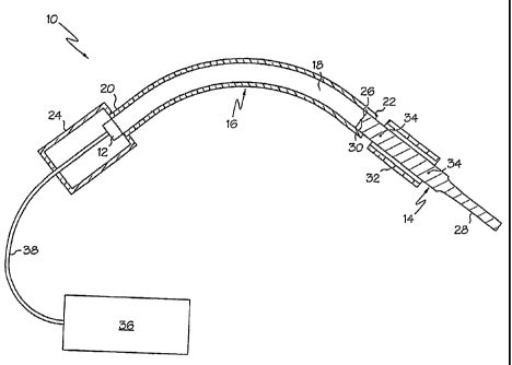
[00201 Referring now to the Figures, in which like numerals indicate like
elements, Figure 1 illustrates a first embodiment of the invention. A first
expression of the embodiment of Figure 1 is for an ultrasonic medical
instrument 10 including an ultrasound transducer 12, a medical ultrasonic
blade
14 (such as, without limitation, a titanium ultrasonic blade), and a tube 16.
The
tube 16 is adapted to contain a liquid 18 and has a first tube end 20 and a
second
tube end 22. The first tube end 22 is adapted to have the liquid 18 proximate
the first tube end 20, when the tube 16 contains the liquid 18, be
ultrasonically
vibrated to generate an ultrasonically-vibrating energy wave. The ultrasonic
blade 14 is acoustically connected to the liquid 18 proximate the second tube
CA 02636276 2008-07-04
WO 2007/081585 PCT/US2006/049641
.4
end 22, when the tube 16 contains the liquid 18. It is noted that the term
"proximate" includes, without limitation, the word "at". In one example, not
shown, the tube is a rigid tube.
[0021] In one enablement of the first expression of the embodiment of Figure
1, the tube 16 is a flexible tube and is filled with the liquid 18. In the
same or a
different enablement, the liquid 18 is an at-least-partially de-gassed liquid
or an
essentially de-gassed liquid. In one example, the de-gassed liquid is less
prone
to cavitation when ultrasonically vibrated than if not de-gassed. In the same
or
a different enablement, the liquid 18 is a pressurized liquid. In one example,
the
pressurized liquid is less prone to cavitation when ultrasonically vibrated
than if
not pressurized. In the same or a different enablement, the liquid 18 consists
essentially of water or mineral oil.
[00221 In one construction of the first expression of the embodiment of Figure
1, the ultrasonic blade 14 has a proximal blade end 26 and a distal blade
portion
28, and the distal blade portion 28 is adapted to contact and medically treat
patient tissue. In one variation, the ultrasonically-vibrating energy wave has
a
vibration antinode 30, and the proximal blade end 26 is disposed proximate the
vibration antinode 30. In one illustration, the ultrasonically-vibrating
energy
wave is transmitted as pressure pulses through the liquid 18, and the
ultrasonic
blade 14 is held to the tube 16 in a manner which allows, when the pressure
pulse is transmitted, the proxirnal blade end 26 to move and return the energy
to
motion.
100231 In one modification, the ultrasonic medical instrument 10 includes a
housing 24 containing the ultrasound transducer 12, wherein the tube 16 is
attached to the housing 24. In one deployment, the housing 24 and the tube 16
essentially do not vibrate. In one example, the housing 24 and the tube 16 are
adapted to be held.by a user when the distal blade portion 28 contacts and
medically treats patient tissue. In one arrangement, the ultrasonic medical
instrument 10 includes an ultrasound generator 36 disposed outside the housing
CA 02636276 2008-07-04
WO 2007/081585 PCT/US2006/049641
24 and, operatively connected to the ultrasound transducer 12 (such as by a
long
cable 38).
[0024] In a different example, as shown in the alternate embodiment of Figure
2 and with the sheath 132 being omitted, the tube 116, but not the housing
124,
is adapted to be held by a user when the distal blade portion 128 contacts and
medically treats patient tissue. In a different arrrangement, as shown in the
alternate embodiment of Figure 2, the ultrasonic medical instrument 110 also
includes an ultrasound generator 136 disposed inside the housing 124 and
operatively connected to the ultrasound transducer 112 (such as by a short
cable
138).
[00251 In one configuration, as shown in the alternate embodiment of Figure
'3, the tube 216 has a shoulder 217 between the first and second tube ends 220
and 222. In this configuration, the tube 216 has a first inside diameter
between
the first tube end 220 and the shoulder 217, and the tube 216 has a second
inside
diameter between the shoulder 217 and the second tube end 222, wherein the
fust-diameter is not equal to the second diameter. This provides a gain step
in
the pressure pulse. The gain step is greater than unity when the first
diameter is
greater than the second diameter as shown in Figure 3. The gain step is less
than unity when the first diameter is less than the second diameter (not
shown).
The embodiment of Figure 3 also shows the ultrasound transducer 212, the
ultrasonic blade 214, the housing 224, the ultrasound generator 236, and the
cable 238 of the ultrasonic medical instrument 210. It is noted that in the
embodiment of Figure 3, there is no sheath present.
[0026] In a first employrhent of the first expression of the embodiment of
Figure 1, the ultrasonic medical instrument 10 includes a sheath 32
surrounding
and attached to the ultrasonic blade 14. In one example, the attached
ultrasonic
blade 14 has at least one vibration node 34, and the sheath 32 is attached to
the
ultrasonic blade 14 proximate the at-least-one vibration node 34 of the
attached
ultrasonic blade 14. In one variation, the sheath 32 is flexible and does not
extend to the housing 24. In one variation, the sheath 32 and the housing 24
are
CA 02636276 2008-07-04
WO 2007/081585 PCT/US2006/049641
6
adapted to be held by a user when the distal blade portion 28 contacts and
medically treats patient tissue. In one technique, the tube 16 is a relatively
short
tube, and the user manipulates the hand-held sheath 32 relative to the hand-
held
housing 24 to bend the tube 16 during a medical procedure to allow the
ultrasonic blade 14 to triore easily access a target site in a patient.
(00271 In a second employment, as shown in the alternate embodiment of
figure 2, the sheath 132 of the ultrasonic medical instrument 110 surrounds
and
is attached to the tube 116. In one variation, the sheath 132 extends at least
from the proximal blade end 126 to the housing 124. In one modification, the
sheath 132 has a flexible portion 140 (which can extend the entire length of
the
sheath) and the sheath 132, but not the housing 124, is adapted to be held by
a
user when the distal blade portion 128 contacts and medically treats patient
tissue. In one technique, the tube 116 is a relatively long tube, the housing
124
is located on the floor (or other suitable location) and the user manipulates
the
hand-held sheath 132 relative to the non-hand-held housing 124 to bend the
tube
116 during a medical procedure to allow the ultrasonic blade 114 to more
easily
access a target site in a patient.
[00281 In a third employment, not shown, wherein the tube is a flexible tube
and the sheath surrounds the tube and extends from at least the proximal blade
end to the housing, the sheath is a remotely-controlled articulating sheath
(similar to the insertion tube of a flexible endoscope) which is attached to
the
tube.
[00291 Referring again to the Figures, Figure 4 illustrates a second
embodiment of the invention. A first expression of the embodiment of Figure 4
is for an ultrasound medical instrument 42 including a heat pulse initiator
44, a
medical ultrasonic blade 46, and a tube 48. The heat pulse initiator 44 is
adapted to output heat pulses having an ultrasonic pulse frequency. The tube
48
is adapted to contain a liquid 50 and has a fust tube end 52 and a second tube
end 54. The first tube end 52 is adapted to receive the heat pulses outputted
by
the heat pulse initiator 44. The ultrasonic blade 46 is acoustically connected
to
CA 02636276 2008-07-04
WO 2007/081585 PCT/US2006/049641
7
the liquid 50 proximate the second tube end 54, when the tube 48 contains the
liquid 50. It is noted that the heat pulses have an energy sufficient to take
the
liquid 50 to its critical temperature, in tum causing the liquid 50 to expand
and
from a pressure wave which then creates an ultrasonically-vibrating energy
wave in the liquid 50, as can be appreciated by those skilled in the art. In
one
implementation, the tube 48 is filled with the liquid 18. In one example, not
shown, the tube is a flexible tube.
[00301 In one enablement of the first expression of the embodiment of Figure
4, the tube 48 is a rigid tube. In application of the first expression of the
embodiment of Figure 4," the heat pulse initiator 44 is driven by an electric
power source 56, and the heat pulse initiator 44 includes an end 58 of a
resistive
or a (bipolar) radio-frequency flexible wire 60 operatively connected to the
electric power source 56. In one arrangement, not shown, the heat pulse
initiator includes the ends of a plurality of resistive or radio-frequency
flexible
wires. In a different application, as shown in the alternate embodiment of
Figure 5, the heat pulse initiator 144 is driven by a laser light source 156,
and
the heat pulse initiator 144 includes an end 158 of a flexible laser fiber 160
operatively connected to the laser light source 156. In one arrangement, not
shown, the heat pulse initiator includes the ends of a plurality of flexible
laser
fibers. Other heat pulse initiators are left to those skilled in the art.
[0031] It is noted that the variations, constructions, employments (including
sheaths), etc. of the first embodiment of Figure 1 and alternate embodiments
of
Figures 2 and 3 are equally applicable to the first expression of the second
embodiment of Figure 4 and the alternate embodiment of Figure 5 substituting
"heat pulse initiator" for "ultrasound transducer".
[0032] Several benefits and advantages are obtained from one or more of the
embodiments of the invention. In one example of the first and/or the second
embodiment, the tube is a flexible tube and is controllably bent by a user
during
a medical procedure to allow the medical ultrasonic blade to more easily
access
a target site in apatient.
CA 02636276 2008-07-04
WO 2007/081585 PCT/US2006/049641
8
(00331 While the present invention has been illustrated by a description of
several embodiments, it is not the intention of the applicant to restrict or
limit
the spirit and scope of the appended claims to such detail. Numerous other
variations, changes, and substitutions will occur to those skilled in the art
without departing from the scope of the invention. For instance, the
ultrasonic
medical instrument has application in robotic assisted surgery taking into
account the obvious modifications of such systems, components and methods to
be compatible with such a robotic system. It will be understood that the
foregoing description is provided by way of example, and that other
modifications may occur to those skilled in the art without departing from the
scope and spirit of the appended Claims.
WHAT IS CLAIMED IS: