Note: Descriptions are shown in the official language in which they were submitted.
CA 02636370 2008-07-04
WO 2008/002328 PCT/US2006/049469
INTERACTIVE SECURITY SCREENING SYSTEM
BACKGROUND OF THE INVENTION
1. Field of the Invention
The present invention pertains to the art of security screening
s systems and, more particularly, to an interactive security screening
system that focuses a sample processing system on particular portions of
a collected sample and employs one or more processes to screen the
collected sample for threat residue.
CA 02636370 2008-07-04
WO 2008/002328 PCT/US2006/049469
2. Discussion of the Prior Art
Since September 11, 2001, protection against terrorist threats has
become a national priority. This priority extends from the protection of
government facilities inside the U.S. and abroad to the protection of
private businesses and venues. Various types of threats have been
postulated, including attacks using explosive, chemical and biological
agents, as well as nuclear and radiological (dirty) bombs. The diversity
of this threat has created complex security challenges for national, state,
and local governments, the transportation industry, private businesses,
to and even individuals. Total expenditures related to Homeland Security
topped $100B in one year and billions more have been allocated in
Federal, Supplemental Appropriations, and State/Local spending.
Increasingly, U.S. businesses are devoting more revenue to security
systems, with expenditures reaching tens of billions. Growth in the
homeland security industry is expected to be vigorous over the next
decade. Motivated by the wide diversity of potential threats and by the
inadequacy of currently available systems, government investments in
research and development are strong.
Of the various threats postulated, explosives remain the number
one choice of terrorists. Indeed, many experts and reports have noted
that, in the case of terrorist activity, the statistical evidence is
compelling,
the primary threat is bombs. At present, two types of detection systems
are in use to combat this threat, i.e., bulk detection systems and trace
detection systems. Bulk detection systems identify the presence of a
large or threat quantity of explosives. In contrast, trace detection systems
identify the presence of residual contamination associated with
2
CA 02636370 2008-07-04
WO 2008/002328 PCT/US2006/049469
explosives. That is, trace detection identifies whether an object or person
has come into contact with or handled explosives.
Bulk systems can cost more than $1 M per portal, while trace
detection system generally run in the order of tens of thousands of
dollars. Often times, installation and annual maintenance costs will
exceed the original price of the system. In the case of trace explosive
detection, currently deployed systems were developed primarily for the
use of analytical chemists in laboratories and only later adapted for field
use. Unfortunately, these systems suffer from long clearance times
io following a positive detection (15 - 30 minutes), have exceedingly high
false alarm rates and require extensive training to ensure proper use and
maintenance. Given the high price associated with the use of bulk
detection systems and their lack of suitability for many screening tasks,
such as the screening of people, trace detection systems are used with
increased frequency and are most often selected for applications outside
of aviation security.
The use of trace explosive detection systems is based on widely
accepted scientific evidence indicating that handling or otherwise
contacting explosives leaves trace residue on hands, clothes, and other
materials or surfaces. The trace residue is of a high concentration and is
difficult to eradicate. The entire justification for the Federal Aviation
Administration's trace explosive detection program is based on this fact.
Indeed, contamination is expected to be so extensive and difficult to
eliminate that currently installed aviation trace explosive detection ,
systems depend on secondary contamination, i.e., contamination
transferred from an individual's hands and clothes to their baggage.
3
CA 02636370 2008-07-04
WO 2008/002328 PCT/US2006/049469
Thus, the baggage is sampled for trace explosives and subjected to
detection systems for analysis. While currently deployed trace detection
systems have high sensitivity, the systems suffer from high operational
burdens, poor sampling efficiencies, high false alarm rates and low
s throughput.
It is known that explosive contamination can vary widely over
small spatial distances. Studies have shown that trace residue levels can
differ by 10,000 fold over distances as small as a few centimeters.
Unfortunately, currently'available trace explosive detection systems
io sample only from limited spatial areas, retain no sample spatial
information and recover samples from only a small section of the sample
acquisition surface. By sampling from only a small area, often times
trace residue is not detected even when present at detectable levels
elsewhere on the sample acquisition surface. In addition, currently
i s available sample acquisition methods are not optimized to collect
particulates in the size and size range distribution most pertinent for
explosives detection. In particular, most conventional trace detection
systems, such as ion mobility spectrometers, require that the sample
acquisition surface be clear of substances that could interfere with the
20 measurement. Unfortunately, many substances that would improve the
efficiency of sample recovery, such as adhesives, are not compatible with
conventional systems and therefore cannot be utilized.
The need for a pristine sample acquisition surface or medium has
resulted in two primary sample acquisition methods employed in existing
25 trace detection systems such as swabbing (or swiping) an object and air
jets that dislodge and test residue from an object. However, both of these
4
CA 02636370 2008-07-04
WO 2008/002328 PCT/US2006/049469
methods are limited in sample recovery efficiency and, as stated above,
fail to retain any of the spatial information of the sample or surface.
Simple swabbing (or swiping) methods tend to leave large particles on
the surface, typically recovering only smaller particles. Other methods,
such as the above described air jet systems, often times dislodge larger
particles, but leave smaller particles on the surface. Simply put, both of
these techniques fail to recover a significant fraction of the existing trace
contamination.
In addition to the above described shortcomings, problems exist
io with sample reproducibility when using swabbing techniques. Extensive
operator training is required to achieve even moderately reproducible
results. The required operator training not only significantly increases
operational costs, but the intensity of operator involvement required to
obtain a good and consistent sample significantly reduces throughput
ts rates. In any case, additional information, particularly more detailed
information regarding a likely spatial distribution of trace sample
collection, would not only improve the probability of detection but, by
eliminating areas that are not relevant and by permitting image analysis
as a secondary level of processing, also improve the signal-to-noise ratio.
20 Currently available systems do not permit such resolution.
Finally, existing systems do not to provide feedback to the operator
or subject as to the reliability of contact or the force applied during
contact (which can impact collection efficiency) and, as such, often fail to
achieve adequate sample recovery. In addition to preserving some spatial
25 information about the sample, there is also a need to determine where, on
the sampling surface, the trace contamination is most likely to be present.
5
CA 02636370 2008-07-04
WO 2008/002328 PCT/US2006/049469
Tn conventional swabbing systems and in novel systems that enable wider
area analysis, such information would improve the signal-to-noise ratio of
the analysis by focusing the detection and analysis on the area with the
highest likelihood of contamination and by eliminating background
signals that can cause unnecessary false alarms.
Therefore, despite the existence in the art of security screening
systems, there still exists a need for an improved security screening
system. More specifically, there exists a need for an interactive security
screening system that provides feedback to test subjects and focuses
io detection on portions of a sample that are most likely to contain trace or
threat residue.
SUMMARY OF THE INVENTION
The present invention is directed to a interactive security screening
system including a main housing, a contact pad provided in the main
housing and a sample collection sheet positioned upon the contact pad.
To initiate a screening process, a subject is asked to contact the sample
collection sheet which then collects and retains a trace residue sample for
analysis. A sensor is operatively connected to the contact pad and
configured to measure a pressure applied to the contact pad during a
sample collection process. In accordance with the invention, the
screening system includes a feedback system operatively connected to the
contact pad and the sensor. The feedback system provides the subject or
screener with at least one of a visual signal and an audio signal indicating
whether a proper sample has been collected.
6
CA 02636370 2008-07-04
WO 2008/002328 PCT/US2006/049469
Once a proper sample is collected, the sample is passed to a sample
processing system which scans and analyzes the sample collection sheet
to deternline whether the trace residue sample contains a threat residue.
The sample processing system includes an analyzing portion that employs
series processing when maximum scanning accuracy is desired, parallel
processing when maximum throughput is necessary or image processing
when it is particularly advantageous to remove areas which are not of
interest from the sample prior to screening or evaluation. Regardless, the
screening system employs a spatial recognition system that focuses the
io analyzing portion on particular sections of the sample. In this manner,
the overall accuracy of the screening system is increased, thereby
resulting in fewer false positive results which tend to slow the scanning
process, inconvenience individuals and place an unnecessary burden on
security personnel.
Additional objects, features and advantages of the present
invention will become more readily apparent from the following detailed
description of preferred embodiments when taken in conjunction with the
drawings wherein like reference numerals refer to corresponding parts in
the several views.
BRIEF DESCRIPTION OF THE DRAWINGS
Figure 1 is an upper left perspective view of a screening center
including a dynamic user feedback and processing system constructed in
accordance with the present invention;
7
CA 02636370 2008-07-04
WO 2008/002328 PCT/US2006/049469
Figure 2 is a cross-sectional side view of the screening center of
Figure 1;
Figure 3 is a detailed view of a palm sensor portion of the
screening ceinter;
Figure 4 is a representative view of a sample obtained during a
screening process employing the screening center of Figure 1;
Figure 5 is a block diagram outlining a screening process in
accordance with one aspect of the present invention;
Figure 6 is a block diagram outlining a screening process in
io accordance with another aspect of the present invention; and
Figure 7 is a block diagram outlining a screening process in
accordance with yet another aspect of the present invention.
DETAILED DESCRIPTION OF THE PREFERRED
EMBODIMENTS
As will become more fully evident below, the present invention
can take various forms in connection with scanning for various potential
th.reats. However, initial reference is made to Figures ] and 2 in
describing a security screening center or kiosk 2 constructed in
accordance with a preferred embodiment of the present invention.
Screening center 2 includes a main housing 4 provided with a front wall
8
CA 02636370 2008-07-04
WO 2008/002328 PCT/US2006/049469
6, a rear wall 7, a top wall 8, a bottom wall or base 9 and opposing side
walls 10 and 11. In addition, screening center 2 is provided with various
accessories to enhance an overall aesthetic appearance of main housing 4
and help screening center 2 blend in or match a particular venue or
location. For example, in the embodiment shown, screening center 2 is
shown with a pair of columns 17 and 18, that, in connection with various
colored plaques or murals (not shown) attached to either rear wal17 or
side walls 10 and 11, provide a readily adaptable enhanced aesthetic
appearance to screening center 2 that matches or blends with the
io particular venue at which screening center 2 is deployed.
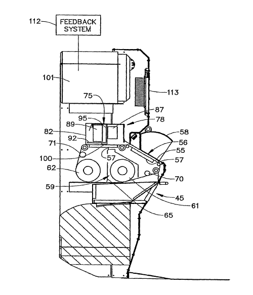
Screening center 2 includes a sample collecting portion 34
arranged within a housing 37 that retrieves trace residue samples and, in
certain instances, demographic samples from a subject. As such,
collecting portion 34 includes a residue sample collector 38, a
i s demographic sample collector (not shown) and an output portion 45
which, as will be described more fully below, outputs or issues an article
to the subject upon completion of a screening process.
In accordance with the invention, residue sample collector 3 8
includes a sample collecting sheet 55 positioned upon a palm pad 56. A
zo pressure sensor 57 is arranged below palm pad 56 and, as will be detailed
more fully below, functions to provide feedback to the subject during a
sample collection process. In order to protect sample collecting sheet 55
from various environmental factors, palm pad 56 is positioned below a
cowl 58. To ensure proper sample screening, fresh sampling media is
zs provided for each screening process. Towards that end, sample collecting
sheet 55 is provided on a continuous roll 59 including a first spool or new
9
CA 02636370 2008-07-04
WO 2008/002328 PCT/US2006/049469
media portion 61 and a second spool or used media portion 62 which are
separated by a shield 65 and a seal 67. Tension is applied to collection
sheet 55 by a pair of tensioning rollers 70 and 71, while guide rollers (not
separately labeled) are provided to ensure proper positioning upon palm
pad 56. Application details of the overall structure operation and
application for security center 2 can be found in commonly assigned U.S.
Patent Application Serial No. 11/418, i 93 filed on May 5, 2006
incorporated herein by reference.
In a manner that will be discussed more fully below, after obtaining
io a sample, sample collecting sheet 55 is moved to a sample processing
system 75 including an analyzer portion 78. As shown, analyzer portion
78 includes a housing or light proof chamber 82 within which is
positioned an applicator 87 and an image capturing unit or scanner 89.
Arranged below image scanner 89 is a clear shield 92. Another shield 95
separates applicator 87 from image scanner 89. A heater 100 is mounted
to an underside of clear shield 92. Heater 100 is activated when
necessary to warm agents applied by applicator 87 or to warm the sample
sheet to facilitate the screening process. In a manner that will be
described more fully below, during the screening process, analyzer
portion 78 performs one of several pre-programmed scanning processes
on the sample. The particular process employed depends upon various
circumstances, such as desired accuracy, throughput or the presence of
contaminants. In any case, following analysis of the sample, a controller
portion 101 determines whether the sample contains a threat residue.
In order to ensure the collection of a proper sample, palm pad 56
includes pad sensor 57 having a pixel array 110 operatively coupled to
CA 02636370 2008-07-04
WO 2008/002328 PCT/US2006/049469
controller 101. More specifically, upon approaching screening center 2, a
test subject places his or her hand upon palm pad 56 and applies pressure
to sample collection sheet 55. Preferably, sample collection sheet 55 is
provided with an adhesive coating selected for moderate tackiness and
skin contact compatibility and in order to minimize background
fluorescence or luminescence. In addition, sample collection sheet 55
may have embedded therein various catalysts or precursors to support
subsequent analysis or processing steps. = For instance, zinc particulates or
powder can be employed.
To ensure that sufficient pressure has been applied over a wide
enough area for efficient sample recovery and to improve reproducibility
of sample acquisition, screening center 2 includes a dynamic feedback
system 112. If necessary, feedback system 112 provides visual and/or
audible queues to the subject when additional pressure should be applied
to palm pad 56. That is, the pressure applied to palm pad 56 must be of a
sufficient force so as to obtain a suitable sample. Visual cues can be
provided on a screen portion 113 provided in housing 4 or, as stated
above, audible cues, such as "apply more pressure," can be signaled from
screening center 2. In any event, once the subject has applied sufficient
pressure, a proper sample 114 is obtained.
In order to maximize sample analysis, screening center 2 also
includes a spatial recognition system 115 (see Figure 3) that performs a
spatial analysis on sample 114. Spatial recognition system 115 utilizes
pixel array i 10 on pad sensor 57 to designate particular areas of interest
on sample 114, such as A1-A8 (see Figure 4). More specifically, studies
have shown that particular portions of a hand are more likely to include
tl
CA 02636370 2008-07-04
WO 2008/002328 PCT/US2006/049469
trace residue than others. Thus, spatial recognition system 115 enables
analyzer portion 78 to focus on particular points of interest A1-A8 of the
obtained sample 114 in order to increase the reliability of the screening
process. Once spatial analysis is complete, sample collection sheet 55 is
s shifted into analyzer portion 78 and the screening process continues.
In accordance with the invention, analyzer portion 78 employs one
or more processes when screening sample 114. The particular process
employed depends upon a desired depth of analysis, a required level of
throughput or other security demands. More specifically, if there is a
io need to maximize a probability detection, series processing, such as
illustrated in Figure 5, is preferably employed by analyzer portion 78.
Alternatively, analyzer portion 78 can also be programmed to perform
parallel processing (Figure 6) when high throughput is desired. Finally,
image processing, illustrated in Figure 7, which digitally removes
15 potentially interfering substances (or areas unlikely to contain the
desired
sample) from the detection process to compensate for process
inconsistencies or background imperfections, can be employed, either
alone or in combination with another analysis process. In general, image
processing both increases detection accuracy and reduces false alarm
2o rates.
As best shown in Figure 5, serial processing involves sequentially
passing sample 114 through a chemical application and illumination
process. That is, after designating areas of interest A1-A8, sample
collection sheet 55 is moved into analyzer portion 78 where a first
25 chemical application process 140 is initiated. Following application of
one or more chemical agents, sample collection sheet 55 is illuminated in
12
CA 02636370 2008-07-04
WO 2008/002328 PCT/US2006/049469
step 143. Other processing steps, particularly the activation of heater 100
to activate a particular applied chemical agent or otherwise aid in
analysis, are performed in step 146. After processing step 146 is
complete, an image is acquired by image scanner 89 and analyzed for
threat residue in step 149. This overall process can be repeated one or
more times with different chemical applications, depending upon a
desired level of accuracy and the particular trace residue of interest.
Upon completion of series processing, analyzer portion 78 outputs a
result 157 to controller 101. Result 157 can be presented to the test
to subject on a keepsake (not shown) that is issued through output portion
45 or, alternatively, passed to a central security station (not shown) for
review and further analysis.
As stated above, if higher throughput is required, for example in
order to expeditiously accommodate larger crowds, analyzer portion 78
can be programmed to perform parallel processing on sample 114. As
best shown in Figure 6, after designating areas of interest A1-A8, sample
collection sheet 55 is passed to analyzer portion 78 for an initial chemical
application process step 163. During chemical application process step
163, multiple chemical agents 165-167 are substantially simultaneously
2o applied to sample collection sheet 55, even as it passes. Following
chemical application process step 163, sample collection sheet 55 is
illuminated in step 175 and subjected to various additional processing
steps at 180, such as the activation of heater 100 to activate the chemical
agents. Illumination step 175 and processing steps 180 can be repeated
one or more times depending upon the chemicals employed and desired
level of accuracy. After illumination and processing steps 175 and 180
are complete, an image is acquired during an image acquisition step 184.
13
CA 02636370 2008-07-04
WO 2008/002328 PCT/US2006/049469
Once the image is obtained, analyzer portion 78 determines whether
sample 114 contains a threat residue in step 188. The result is passed to
controller 101 and, in a manner similar to that described above, either
imprinted upon a keepsake which is issued to the tested subject or passed
to a central control center.
Reference will now be made to Figure 7 in describing an image
processing detection method employed by analyzer portion 78. In a
manner similar to that described above, after designating areas of interest
A1-A8, sample collection sheet 55 is passed to analyzer portion 78. At
1 o this point, a first image capture of sample 114 is performed in step 198.
First image capture 198 is conducted employing white light. Preferably,
image scanner 89 is configured to utilize a visible wavelength. The
image obtained in step 198 is used to identify any physical contaminants
that may be present on sample sheet 55 which might result in false alarms
in the final result. Sample collection sheet 55 is then exposed to
ultraviolet (UV) light in light proof chamber 82 in step 202. At this point,
it should be noted that all image capture steps could be performed in light
proof chamber 82, with only the particular type of illumination, i.e., white
light, UV light, changing as necessary. In any case, while sample
collection sheet is exposed to UV light, a second image is captured in step
205. Preferably, image scanner 89 is sensitive in a wavelength range that
is specific for potential interference, such as white light contaminants that
may fluoresce when subjected to UV light and contaminates that may
absorb UV light. These potential interferences are image captured prior
to step 209.
14
CA 02636370 2008-07-04
WO 2008/002328 PCT/US2006/049469
In step 209, a detection image is captured under the UV light using
image scanner 89 which is preferably set to the same wavelength
employed when capturing image 205. However, various other
wavelengths can be chosen in order to optimize detecting optical changes
consistent with trace explosive residues. In any event, once obtained, the
three images are digitally analyzed in digital processing portion 212 for
evidence of trace explosives. The images are correlated using one or
more common reference points on all images. Preferably, the common
reference points are registered in a calibration portion of internal
to hardware and software, but may also be registered using one or more of
designated areas A1-A8 or pre-made marks on sample collection sheet
55.
The first images obtained in steps 198 and 205 are used to identify
and remove any visible contaminants from the final image obtained in
step 209. More specifically, the image obtained in step 209 is used to
identify and remove any fluorescent and/or UV absorbing contaminants
from the final image such that the known and identified contaminants are
digitally removed from the detection image. The resulting image is then
analyzed for evidence of trace explosive content. Once complete, the
result is passed to controller 101 and, in a manner similar to that
described above, either signified on a keepsake or passed to a central
processing portion.
It should be recognized that the security screening center
constructed in accordance with the present invention is readily adaptable
2s to various venues and/or security levels employing one or more
processing steps in order to ensure a high level of reliability while,
CA 02636370 2008-07-04
WO 2008/002328 PCT/US2006/049469
simultaneously, increasing throughput through screening center 2. In
addition, by providing feedback to test subjects to ensure proper sample
recovery and employing a system that focuses on particular areas of a
sample that are most likely to contain threat residue, the security system
increases the likelihood of identifying potential threats. Furthermore, it
should be realized that sample processing in accordance with the
invention can be done on individual samples, such as with the various
process steps described above being performed on a moving sample or in
sample batches with multiple samples being concurrently processed.
Although described with reference to preferred embodiments of the
invention, it should be readily understood that various changes andior
modifications can be made to the invention without departing from the
spirit thereof. In general, the invention is only intended to be limited by
the scope of the following claims.
16