Note: Descriptions are shown in the official language in which they were submitted.
CA 02636393 2008-06-26
BROADBAND MICROWAVE APPLICATOR
BACKGROUND
1. Technical Field
The present disclosure relates generally to microwave applicators used in
tissue
ablation procedures. More particularly, the present disclosure is directed to
a microwave
applicator having broadband matching performance over a band spanning a wide
spectrum of
operation frequencies.
2. Background of Related Art
Treatment of certain diseases requires destruction of malignant tissue growths
(e.g.,
tumors). It is known that tumor cells denature at elevated temperatures that
are slightly lower
than temperatures injurious to surrounding healthy cells. Therefore, known
treatment
methods, such as hyperthermia therapy, heat tumor cells to temperatures above
41 C, while
maintaining adjacent healthy cells at lower temperatures to avoid irreversible
cell damage.
Such methods involve applying electromagnetic radiation to heat tissue and
include ablation
and coagulation of tissue. In particular, microwave energy is used to
coagulate and/or ablate
tissue to denature or kill the cancerous cells.
Microwave energy is applied via microwave ablation antenna probes which
penetrate
tissue to reach tumors. There are several types of microwave probes, such as
monopole and
dipole. In monopole and dipole probes, microwave energy radiates
perpendicularly from the
axis of the conductor. Monopole probe (e.g., antenna) includes a single,
elongated
microwave conductor. Dipole probes have a coaxial construction including an
inner
conductor and an outer conductor separated by a dielectric portion. More
specifically, dipole
microwave antennas have a long, thin inner conductor which extends along a
longitudinal
1
CA 02636393 2008-06-26
axis of the probe and is surrounded by an outer conductor. In certain
variations, a portion or
portions of the outer conductor may be selectively removed to provide for more
effective
outward radiation of energy. This type of microwave probe construction is
typically referred
to as a "leaky waveguide" or "leaky coaxial" antenna.
Conventional microwave probes have a narrow operational bandwidth, a
wavelength
range at which optimal operational efficiency is achieved, and hence, are
incapable of
maintaining a predetermined impedance match between the microwave delivery
system (e.g.,
generator, cable, etc.) and the tissue surrounding the microwave probe. More
specifically, as
microwave energy is applied to tissue, the dielectric constant of the tissue
immediately
surrounding the microwave probe decreases as the tissue is cooked. The drop
causes the
wavelength of the microwave energy being applied to tissue to increase beyond
the
bandwidth of the probe. As a result, there is a mismatch between the bandwidth
of
conventional microwave probe and the microwave energy being applied. Thus,
narrow band
microwave probes may detune hindering effective energy delivery and
dispersion.
SUMMARY
The present disclosure provides for a microwave ablation probe configured to
maintain an impedance match to impedance of a microwave energy delivery system
(e.g.,
microwave generator, cable, etc.) despite tissue state changes encountered
during the course
of the microwave ablation as the dielectric constant of the tissue changes.
The microwave
ablation probe is passively broadband in nature (e.g., a band spanning 40% of
the frequency
of the microwave energy) due to the structure of the probe. In embodiments,
the probe
includes either a balanced or an unbalanced coaxial fed dipole antenna having
one or more
2
CA 02636393 2008-06-26
capacitive metallic disks and/or dielectric materials at a radiation portion
of the probe. In
other embodiments, the probe includes the so-called "folded-dipole" antenna
disposed in the
radiation portion of the probe which is also loaded with dielectric materials.
According to one embodiment, a microwave ablation probe for providing
microwave
energy to tissue is disclosed. The probe includes a feedline having an inner
conductor, an
insulating spacer and an outer conductor. The probe also includes a radiation
portion having
an extruded portion of the inner conductor that is centrally disposed therein.
The radiation
portion also includes one or more conductive disks disposed on the extruded
portion of the
inner conductor that defines one or more spaces and a dielectric material
disposed within the
spaces.
According to another embodiment, a microwave ablation probe for providing
microwave energy to tissue is disclosed. The probe includes a feedline having
an inner
conductor, an insulating spacer and an outer conductor. The probe also
includes a radiation
portion including a folded-dipole antenna constructed from an extruded portion
of the inner
.. conductor and at least one outer arm coupled to the outer conductor. The
radiation portion
further includes a dielectric material disposed around the folded-dipole
antenna.
According to a further embodiment of the present disclosure, a microwave
ablation
probe for providing microwave energy to tissue is disclosed. The probe
includes a feedline
having an inner conductor, an insulating spacer and an outer conductor. The
probe also
includes a radiation portion having an extruded portion of the inner conductor
that is centrally
disposed therein. The radiation portion also includes one or more disks
disposed on the
extruded portion of the inner conductor that define one or more corresponding
spaces. The
3
CA 02636393 2016-08-09
radiation portion also includes one or more supply tubes configured to supply
a liquid cooling
dielectric material into the spaces.
In accordance with one embodiment of the present invention, there is provided
a
microwave ablation probe for providing microwave energy to tissue, the probe
comprising: a
feedline including an inner conductor, an insulating spacer and an outer
conductor; a radiation
portion including at least a portion of the inner conductor that is centrally
disposed within the
radiation portion, the radiation portion including at least two conductive
disks disposed within a
housing and the inner conductor dividing the radiation portion to define a
corresponding number
.. of spaces; and a dielectric material disposed within the spaces.
Yet another embodiment provides a microwave ablation probe for providing
microwave
energy to tissue, the probe comprising: a feedline including an inner
conductor, an insulating
spacer and an outer conductor; a radiation portion including at least a
portion of the inner
conductor that is centrally disposed within the radiation portion, the
radiation portion including
at least two disks disposed within a housing and on the inner conductor
dividing the radiation
portion to define a corresponding number of spaces; and at least one supply
tube configured to
supply a liquid cooling dielectric material into the spaces.
=
4
CA 02636393 2016-08-09
A further embodiment of the present invention provides a microwave ablation
probe for
providing microwave energy to tissue, the probe comprising: a housing defining
a cavity therein;
a feedline disposed in the cavity and including an inner conductor, an
insulating spacer and an
outer conductor; a radiation portion disposed within the cavity and including
a folded-dipole
antenna constructed from at least a portion of the inner conductor and a first-
outer arm having a
proximal portion coupled to the outer conductor and a distal portion coupled
to the inner
conductor, the proximal and distal portions of the first outer arm disposed
perpendicular relative
to one another; and a dielectric material disposed within the cavity such that
the outer conductor
of the feedline and the first outer arm of the folded-dipole antenna are in
contact with the
dielectric material.
A still further embodiment provides a microwave ablation probe for providing
microwave energy to tissue, the probe comprising: a housing defining a cavity
therein; a feedline
disposed within the cavity and including an inner conductor, an insulating
spacer and an outer
conductor; a radiation portion disposed within the cavity and coupled to the
feedline, the
radiation portion including a folded-dipole antenna including a distal portion
of the inner
conductor extending distally beyond a distal portion of the outer conductor
and a first outer arm
having a distal portion coupled to the distal portion of the inner conductor
and a proximal portion
coupled to the distal portion of the outer conductor, the proximal and distal
portions of the first
outer arm disposed perpendicular relative to one another; and a dielectric
material disposed
within the cavity such that the outer conductor of the feedline and the first
outer arm of the
folded-dipole antenna are in contact with the dielectric material.
4a
CA 02636393 2016-08-09
=
BRIEF DESCRIPTION OF THE DRAWINGS
The above and other aspects, features, and advantages of the present
disclosure will
become more apparent in light of the following detailed description when taken
in
conjunction with the accompanying drawings in which:
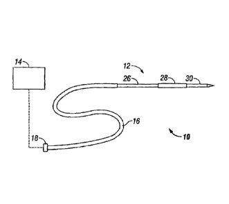
Fig. 1 is a'schematic diagram of a microwave ablation system according to the
present
disclosure;
Fig. 2 is a perspective cross-sectional view of a microwave ablation probe
according
to the present disclosure;
Fig. 3 is a perspective view with parts disassembles of the microwave ablation
probe
of Fig. 2.
Fig. 4 is a side cross-sectional view of the microwave ablation probe of Fig.
2;
Fig. 5 is a perspective cross-sectional view of the microwave ablation probe
having an
supply duct according to the present disclosure; and
Fig. 6 is a perspective cross-sectional view of one embodiment of the
microwave
ablation probe having an supply duct according to the present disclosure.
DETAILED DESCRIPTION
Particular embodiments of the present disclosure will be described herein
below with
reference to the accompanying drawings. In the following description, well-
known functions
=
4b
CA 02636393 2008-06-26
or constructions are not described in detail to avoid obscuring the present
disclosure in
unnecessary detail.
Fig.1 shows a microwave ablation system 10 which includes a microwave ablation
probe 12 coupled to a microwave generator 14 via a flexible coaxial cable 16,
which is, in
turn, coupled to a connector 18 of the generator 14. The generator 14 is
configured to
provide microwave energy at an operational frequency from about 500 MHz to
about 2500
MHz.
During microwave ablation, the probe 12 is inserted into tissue and microwave
energy
is supplied thereto. As tissue surrounding the probe 12 is ablated, the tissue
undergoes
desiccation and denaturization which results in a drop of the effective
dielectric constant of
the tissue (i.e., increase in impedance). The drop in the effective dielectric
constant, in turn,
lengthens the wavelength of the microwave energy. Since the probe length is
held constant
during ablation, the increase in the wavelength results in the increase of the
optimal
operational frequency of the probe. Thus, at the outset the probe 12 is at an
initial match
point - a predetermined operational frequency that increases to a higher
frequency as the
ablation continues. The higher frequency is determined according to the
formula (1), wherein
(cr) is the dielectric constant and f is the frequency:
(1) -q(F:
¨r uncooked / Er cooked) foper = flugh
With respect to liver tissue, in a normal uncooked state, the liver tissue has
a
dielectric constant of 50 with the operational frequency being 915 MHz. In a
cooked state,
the liver tissue has a dielectric constant of 25. Substituting these values
into the formula (1)
provides the lower frequency, which in this case is 1300 MHz. The probe 12
according to the
present disclosure has an operational bandwidth configured to encompass the
initial match
5
CA 02636393 2008-06-26
point as well as the higher frequency. In particular, the bandwidth of the
probe 12 is
approximately 40% of the operational frequency. In embodiments, the probe 12
is loaded
with one or more of the following: one or more disks, liquid and/or solid
dielectric materials.
These materials provide a static envelope around the antenna and act as a
buffer between the
antenna and the tissue. Use of a liquid dielectric material also allows for
active cooling of the
antenna during ablation in addition to providing a dielectric buffer.
As shown in Figs. 2-4, the probe 12 includes a feedline 26, a choke 28 and a
radiating
portion 30. The feedline 26 extends between the distal end of the probe 12
where the
feedline 26 is coupled to the cable 16, to the radiating portion 30. The
feedline 26 is
constructed from a coaxial cable having an inner conductor 20 (e.g., wire)
surrounded by an
insulating spacer 22 which is then surrounded by an outer conductor 24 (e.g.,
cylindrical
conducting sheath). In one embodiment, the feedline 26 may have a diameter of
0.085 inches
and the insulating spacer 22 may have a dielectric constant of 1.7.
The feedline 26 may be flexible or semi-rigid and may be of variable length
from a
proximal end of the radiating portion 30 to a distal end of the cable 16
ranging from about 1
to about 10 inches. The inner conductor 20 and the outer conductor 24 may be
constructed
from a variety of metals and alloys, such as copper, gold, stainless steel,
and the like. Metals
may be selected based on a variety of factors, such as conductivity and
tensile strength. Thus,
although stainless steel has lower conductivity than copper and/or gold,
stainless steel
provides the necessary strength required to puncture tissue and/or skin. In
such cases, the
inner and outer conductors 20 and 24 may be plated with conductive material
(e.g., copper,
gold, etc.) to improve conductivity and/or decrease energy loss.
6
CA 02636393 2008-06-26
The choke 28 of the probe 12 is disposed around the feedline 26 and includes
an inner
dielectric layer 32 and an outer conductive layer 34. The choke 28 confines
the microwave
energy from the generator 14 to the radiating portion 30 of the probe 12
thereby limiting the
microwave energy deposition zone length along the feedline 26. The choke 28 is
implemented with a quarter wave short by using the outer conductive layer 34
around the
outer conductor 24 of the feedline 26 separated by the dielectric layer 32.
The choke 28 is
shorted to the outer conductor 24 of the feedline 26 at the proximal end of
the choke 28 by
soldering or other means. In embodiments, the length of the choke 28 may be
from a quarter
to a full wavelength. The choke 28 acts as a high impedance to microwave
energy conducted
down the outside of the feedline 26 thereby limiting energy deposition to the
end of the
probe. In one embodiment, the dielectric layer 32 is formed from a
fluoropolymer such as
tetrafluorethylene, perfluorpropylene, and the like and has a thickness of
0.005 inches. The
outer conductive layer 34 may be formed from a so-called "perfect conductor"
material such
as a highly conductive metal (e.g., copper).
The probe 12 further includes a tapered end 36 which terminates in a tip 38 at
the
distal end of the radiating portion 30. The tapered end 36 allows for
insertion of the probe
12 into tissue with minimal resistance. In cases where the radiating portion
12 is inserted
into a pre-existing opening, the tip 38 may be rounded or flat. The tapered
end 36 may be
formed from any type of hard material such as metal and/or plastic.
One embodiment of the probe 12 is shown in Figs. 2-4 in which the probe 12
includes
one or more conductive disks 40 loaded therein. The feedline 26 extends past
the distal end
of the choke 28, with the insulating spacer 22 and the outer conductor 24
terminating at the
start of the radiating portion 30. The inner conductor 20 is extruded from the
feedline 26 and
7
CA 02636393 2008-06-26
extends into the radiating portion 30 where the inner conductor 20 is
centrally disposed. The
extruded portion of the inner conductor 20 includes one or more of the
conductive disks 40
which are also centrally disposed thereon (i.e., the center of the disks 40 is
on the longitudinal
axis). The disks 40 are perpendicular to a longitudinal axis defined by the
inner conductor
20. In one embodiment, the disks 40 have a thickness from about 0.01 inches to
about 0.02
inches and have a diameter from about 0.04 inches to about the thickness of
the feedline 26,
which in one embodiment is 0.085 inches. The disks 40 may be of varying size,
diameter and
thickness, or all of the disks 40 may be of the same size. The disks 40 are
spaced on the inner
conductor 20 such that the desired bandwidth is obtained.
The disks 40 divide the radiating portion 30 into a corresponding number of
spaces
42: the spaces 42 between the feedline 26 and the first disk 40, between the
first and second
disks 40, and within the tapered end 36. The spaces 42 are loaded with a solid
dielectric
material 44 which is shaped to fill the corresponding spaces 40 to further
improve the
impedance match between the probe 12 and the generator 14. More specifically,
to fill the
spaces 42 between the disks 40, the material 44 may be cylinder-shaped having
a central
cavity 45 defined therein as illustrated in Fig. 3. The cylinder has an outer
diameter being
substantially equal to the thickness of the feedline 26 and the inner diameter
being
substantially equal to the diameter of the inner conductor 20. To fill the
space 42 at the
tapered end 36, the material 44 may be cone-shaped. In one embodiment, the
material 44 has
a dielectric constant of from about 2.5 and 30 and may be made from a ceramic
material,
such as alumina ceramic or a plastic material, such as a polyamide plastic
(e.g., VESPEL
available from DuPont of Wilmington, Delaware).
8
CA 02636393 2008-06-26
Fig. 5 illustrates another embodiment of the microwave ablation probe 12. The
probe
12 includes the radiating portion 30 coupled to the feedline 26 which is
covered by the choke
28. The feedline 26 includes the inner conductor 20 surrounded by the
insulating spacer 22
which is then surrounded by the outer conductor 24. The inner conductor 20 of
the feedline
.. 26 includes one or more disks 40 perpendicularly disposed thereon. The
feedline 26, at least
a portion of the choke 28, and the radiating portion 30 are enclosed within a
cavity 43 formed
by a moisture-impervious housing 46. The probe 12 also includes one or more
supply tubes
48 that supply a dielectric fluid 45, such as saline solution and the like,
into the cavity 43.
The dielectric fluid 45 provides for an impedance match as well as cools the
probe 12. The
dielectric fluid 45 may be stored in a supply tank (not explicitly shown) and
may be supplied
by a pump (e.g., peristaltic pump) into the cavity 43. The supply tube 48 is
constructed from
a flexible material such as polyamide polymer.
Fig. 6 shows another embodiment of the probe 12 which includes the choke 28
enclosing the feedline disposed within the radiating portion 30. The radiation
portion 30
includes an unbalanced folded-dipole antenna 50 which includes the extruded
inner
conductor 20 as a central arm and one or more outer arms 52 which extend from
and are
coupled to the distal end of inner conductor 20. The outer arms 52 are also
coupled to the
outer conductor 24 of the feedline 26. The outer arms 52 are coupled to the
inner conductor
and the outer conductor 24 by soldering and/or other methods which allow for
conductive
20 coupling of metals. The length of the folded-dipole antenna 50 is
between a quarter and a
full wavelength of the operating microwave energy, effectively providing for
an optimum
impedance match.
9
CA 02636393 2015-08-19
The radiation portion 30, the feedline 26 and the choke 28 are disposed within
the
cavity 43 defined by the housing 46. The cavity 43 also includes one or more
supply tubes
48 which supply the fluid 45 thereto. In embodiments shown in Figs. 5 and 6,
the dielectric
fluid 45 may be circulated through the cavity 43 by continually supplying the
fluid 45 through
the supply tube 48 and withdrawing the fluid using a return tube (not
explicitly shown).
The probe 12 according to the present disclosure has a broadband range
encompassing
the frequency variation encountered during ablation due to tissue state
changes. The probe
12 is configured to maintain an impedance match to the generator 14 and the
cable 16 which
provides for improved microwave deposition and penetration depth that are
maintained
throughout the course of an ablation despite tissue changes.
The described embodiments of the present disclosure are intended to be
illustrative
rather than restrictive, and are not intended to represent every embodiment of
the present
disclosure. Various modifications and variations can be made. The scope of the
claims
should not be limited by the preferred embodiments set forth herein, but
should
be given the broadest interpretation consistent with the description as a
whole.