Note: Descriptions are shown in the official language in which they were submitted.
CD, 02636441 2012-07-27
CERAMIC INTERMITTENTLY SEALABLE REFRACTORY
TILE AND CONTROLLED AIR CONTINUOUS GASIFIERS
The invention disclosed and claimed herein deals with ceramic
intermittently sealable refractory tile and controlled air
continuous gasifiers (rotary kilns) that are manufactured using
such refractory tile, and waste to energy systems that have such
gasifiers as part of the system. The refractory tile and the novel
controlled air continuous gasifiers of this invention form part of
a system that is novel and environmentally effective to directly
convert the latent thermal energy of biomass waste to power
(electricity or steam) without the need for costly processes to
clean contaminated flue gases.
BACKGROUND OF THE INVENTION
A rotary kiln is essentially a slow moving, i.e. rotating,
refractory-lined steel cylinder. To facilitate the movement of
waste material, it generally slants downward from the feed end to
the outlet end. The kiln is heated to high temperatures and as
material passes through the kiln, waste is evaporated, organic
materials are volatized and combustion begins. Generally, rotary
kilns can be designed to operate at temperatures between 1400 and
2600 degrees Fahrenheit. The kiln's end product can be either ash
1
CA 02636441 2008-06-27
,
or slag, depending on the mode of operation and the initial
characteristics of the waste that is fed to the kiln.
Key elements of rotary kiln design are the end seals, drive
assembly, kiln refractory and control systems. The end seals are
designed to minimize leakage of air into the system and prevent
escape of combustion gases. The drive assembly must supply enough
torque to rotate the kiln under all operating conditions.
The
refractory lining (tile) protects the kiln shell from overheating
and chemical attack. At the same time, it provides a hot surface
to aid in ignition and combustion of waste. Refractory surfaces
near the feed inlet are designed for resistance to high impact and
thermal shock loads.
In the discharge area, refractory must
withstand chemical attack and slag penetration.
In the inventive system disclosed and claimed herein using a
rotary kiln of this invention, contaminated flue gas from waste
combustion is used to heat clean air indirectly in a ceramic heat
exchanger to temperatures up to about 2000 degrees Fahrenheit and
clean air side pressures up to about 200 psig to run a gas
turbine. No flue gas treatment is required, and the gas turbine
can discharge clean air for process use rather than combustion
products. The novel refractory tiles of this invention allow for
the processing of waste without slag buildup and thus this
invention eliminates one of the major problems associated with
prior art kilns.
2
CD. 02636441 2008-06-27
1 '
The invention herein destroys biomass and related wastes at
their source and produces electrical power more efficiently than
can be accomplished with conventional steam power plants.
The
system has low leakage in the heat exchangers used therein, and
turbine efficiencies are high owing to the use of controlled
maintenance air instead of combustion products.
Plants using the systems disclosed herein can be sized to
handle large volume, low heat release, wet materials, at the
source, to reduce trucking, storage, and related material handling
situations. This process makes it possible for remote communities
and industries to destroy municipal solid waste, sludge, wood
products and trash and at the same time, generate electricity by
firing a gas turbine with clean air.
THE INVENTION
The invention claimed herein deals with ceramic
intermittently sealable refractory tile and controlled air
continuous gasifiers that are manufactured using such refractory
tile, and waste to energy systems that have such gasifiers as part
of the system.
Thus, this invention deals in one embodiment with a ceramic
intermittently sealable refractory tile comprising a refractory
tile, said refractory tile having a top and a bottom. There is
contained within the refractory tile, an air shaft, having an
external end and an internal end. The external end is surmounted
by a check valve and the internal end opens into a manifold formed
3
CA 02636441 2008-06-27
,
in the top of the refractory tile. The manifold has a bottom,
there being a plurality of channels from the bottom of the
manifold that open through the bottom of the refractory tile.
Unlike the prior art kilns, the kilns of this invention have
better control of the air through the fired bed; have customized
tuyeres/permeable ceramic plates; eliminates the use of a ceramic
ball valve; bears inexpensive construction, and can use standard,
off the shelf check valves for safe operation.
It is important that those in the art recognize that the
kilns of this invention have a counter-flow air flow pattern over
the ash discharge section of the kiln which accomplishes three
things that are important. First, the air cools the ash. Secondly,
the air preheats the combustion air which it will be noted is
introduced below the fuel pile, and thirdly, heated syngas
transfers energy to the drying zone refractory lining. All other
prior art kilns have an airflow pattern across all three sections
of the kiln, which is inefficient.
In another embodiment, there is a ceramic, intermittently
sealable refractory tile comprising a refractory tile, wherein the
refractory tile is formed of air permeable ceramic. The refractory
tile has a top and a bottom, and contained within the refractory
tile is an air shaft, having an external end and an internal end.
The external end is surmounted by a first manifold; the first
manifold has an external end and an internal end. The external end
of the manifold is surmounted by a check valve. The manifold
4
ak 02636441 2008-06-27
internal end surmounts and joins to the external end of the air
shaft. The internal end of the air shaft opens into a second
manifold formed in the top of the refractory tile.
Yet another embodiment is a ceramic intermittently sealable
refractory tile comprising a refractory tile, wherein the
refractory tile has a top and a bottom. There is contained within
said refractory tile, an air shaft that has an external end and a
bifurcated internal end, wherein the external end of the air shaft
has surmounted thereon a check valve. The internal ends of the air
shaft exit through the bottom of the tile.
Still other embodiments of this invention are a controlled
air continuous gasifier containing a plurality of refractory tiles
of the type described just Supra and a waste to energy system
employing a controlled air continuous gasifier.
Going to yet another embodiment of this invention there is a
controlled air, continuous gasifier. The gasifier comprises (i) a
cylinder having a feed end and a product end and comprising three
zones consisting of zone A, a waste heating zone; zone B, a
starved air combustion zone; and zone C, an ash cooling zone.
Component (ii) a feed end cap on the feed end of the cylinder
and component (iii) is a product end cap on the product end of the
cylinder.
Component (iv) is a product exit port in the product end cap
and component (v) a flue gas exit port in the feed end cap.
5
ak 02636441 2008-06-27
Component (vi) is a waste feed port in the feed end cap and
there is component (vii) which is at least one air injection port
near the product end cap, the air injection port joining with an
air manifold, wherein the air manifold is located outside any
ceramic refractory tile of zones B and C and terminates at an
upper end of Zone B.
Component (viii) is a means for allowing rotation of the
gasifier. The cylinder comprises
a. a refractory lined open
center core running essentially the full length of the cylinder.
The refractory lining has an inside surface and an outside
surface; b. a first metal shell covering the entire outside
surface of the refractory lining, the first metal shell having an
outside surface; c. an insulated second metal shell formed
adjacent to, and conforming to, the outside surface configuration
of the first metal shell such that there is a hollow core provided
between the first metal shell and the second metal shell, wherein
the refractory lining of zone B is a ceramic sealable refractory
tile as set forth just Supra.
Another embodiment of this invention is a waste to energy
system comprising in combination at least a. a gasifier as
described just Supra, b. an oxidizer; c. an air to air, all-
ceramic heat exchanger; d. a gas turbine; e. a generator operated
from the gas turbine and f. a filter and compressor driven by the
gas turbine.
6
ak 02636441 2008-06-27
Yet another embodiment of this invention is a waste to energy
system comprising in combination at least: a. a gasifier as
disclosed just Supra; b. an oxidizer; c. an air to air, all-
ceramic heat exchanger; d. a high pressure, medium temperature,
alloy metal air-to air heat exchanger; e. a gas turbine; f. a
generator operated from the gas turbine; and g. a filter and
compressor driven by the gas turbine.
BRIEF DESCRIPTION OF THE DRAWINGS
Figure 1 is a full top view of a gasifier of this invention.
Figure 2 is a cross sectional view of Figure 1, taken through
the line 2-2 of Figure 1.
Figure 3 is an elevation of the feed end of a gasifier of
this invention with the end cap removed.
Figure 4 is a side view of a tile 25A of this invention.
Figure 5 is a cross sectional view of the tile of Figure 4.
Figure 6 is a view in perspective of the ceramic portion of
the tile of Figure 4, showing the exit ports of the air channels.
Figure 7 is a side view of a tile 25B of this invention.
Figure 8 is a cross sectional view of the tile of Figure 7
showing the bifurcated exit ports.
Figure 9 is a side view of a tile 250 of this invention.
Figure 10 is a full top view of an array of the tile of
Figure 9 being fed air using a common manifold.
Figure 11 is a side view of the array of Figure 10.
7
CA 02636441 2008-06-27
Figure 12 is a cross sectional side view through the center
line of a check value useful in this invention.
Figure 13 is a full side view of the tile of 9 wherein the
tile has been mounted on standard fire brick.
Figure 14 is a side view of a tile of this invention in which
its position in the rotation is just after arriving at point E in
Figure 3, wherein the valve 26 is closed.
Figure 15 is a side view of the tile of Figure 14 in which
its position in the rotations is just after arriving at Point D in
Figure 3, wherein the valve 26 is fully open.
DETAILED DESCRIPTION OF THE DRAWINGS
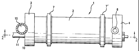
Turning now to the Figures, there is shown in Figure 1, a top
view of a gasifier 1 of this invention.
There is shown a
cylindrical element 2, which is generally an insulated metal
shell. Also shown are the feed end cap 3 and the product end cap
4, along with an air and syngas exit port 5, ignitions and
stabilization burner 36, ash auger 37, air manifold 38 and an air
inlet port 6. Shown at each end of the cylindrical element 2 are
the rotating means 7 and 7'.
With reference to Figure 2, there is shown a cross sectional
view of the gasifier 1 of Figure 1 through line 2-2 wherein there
is shown the feed end cap 3, the product end cap 4, the air inlet
port 6, the refractory lining 8, the air conduction system 9, and,
three zones designated A, B, and C, which will be discussed infra.
Further shown in the feed cap 3 are the flue gas exit port 10 and
8
CD, 02636441 2008-06-27
the waste feed port 11.
With regard to Figure 2, zone A is a preheat and waste
heating zone and does not require the refractory tiles of the
instant invention and therefore, the refractory lining in this
zone can be standard refractory tiles 13.
However, it is
contemplated that the tiles of this invention can also be used if
the particular process required them to be in that zone.
This
zone constitutes on the order of about twenty percent of the
interior volume of the cylindrical element 2.
The feed enters this solid, refractory-lined zone that
contains no air-cooling. The syngas from the combustion process
contains primarily methane, hydrogen, carbon monoxide, carbon
dioxide and water at a temperature below 800 dF. As this mixture
passes over the feed, it drives off water, distills volatiles and
heats the refractory in the preheat zone.
In addition, there is shown zone B, which is the starved air
combustion zone, which constitutes on the order of about sixty to
seventy percent of the interior volume of the cylindrical element
2. A percentage of the stoichiometric air is injected through the
tuyeres into the fuel bed and combusts the fixed carbon to carbon
monoxide. The rotation of the bed through the fuel introduces air
continuously into the fuel as new fuel gently tumbles across the
tuyeres as it moves downward to the exit. Because zone B is the
combustion zone, this zone should be lined with a multiplicity of
the inventive tiles of this invention.
9
CA 02636441 2008-06-27
Zone C is the ash cooling zone and this constitutes on the
order of about twenty percent of the total interior volume of the
cylindrical element 2. The air from the ash discharge housing
bustle is introduced between the outer skin and the kiln shell at
the ash housing. This air passes around the thin refractory-line
kiln section and cools the ash indirectly as it passes over the
kiln shell up to the combustion zone. Since this zone is not a
combustion zone, the lack of direct air through the inventive tile
23 is acceptable, and thus, one need not provide this zone with a
refractory tile of this invention and one can use standard tile 13
in this zone. However, as above, the particular process may
require the use of the inventive tile of this invention in this
zone and such a use is contemplated within the scope of this
invention.
The above-described arrangement is the direct opposite
arrangement of the gasifier and process described in U.S. Patent
6,381,963, In that design, the air starts at the preheat zone and
flows into the combustion zone, and continues on through the ash
zone. Therefore, it cools the preheat zone and heats the ash zone
using energy that it picked up from the entire length of the kiln
as it travels from the feed end to the ash discharge housing. In
the inventive process, the air is introduced at the ash discharge
housing and taken off before it reaches the preheat zone.
Thus, it is contemplated within the scope of this invention
CA 02636441 2008-06-27
to use a multiplicity of the inventive tile in the refractory
lining 8 in combination with standard tile 13, and it is also
contemplated within the scope of this invention to provide for the
whole of zone B to be made up of the inventive tile. The
designation 13 denotes standard fire brick, but is also used to
shown standard fire brick construction material, such as in Figure
5, 8 and 9.
During processing, air is introduced into the air conduction
system 9, and the air is allowed to move through the air
conduction system 9. However, a certain portion of the air is
conducted to zone B, wherein it moves into the inventive
refractory tiles through open air shafts, all of which will be
discussed infra. The movement of the air in this manner differs
from some of the prior art, in which air is introduced directly
into the cylindrical element 2 through the product end cap 4, and
directly into the combustion zone B and on through the zone A and
out the exit 5.
When air is introduced as stated in the prior art. The method
is ineffective in that a lot of the air moves through the gasifier
and exits with the flue gas and is lost. Also, the control of
combustion is difficult in that the air is not moved to the
combustion mass in a constant and consistent manner such that the
rate that each portion of the combusting mass uses is inconsistent
and therefore, the combustion is inconsistent and permits the huge
build up of slag. Removing the slag is a major problem and often
11
CD. 02636441 2008-06-27
leads to a clogged gasifier and provides other major problems,
including a large amount of ash that has to be collected and
handled.
Figure 14 is a side view of a tile of this invention in which
its position in the rotation is just after arriving at point E in
Figure 3, wherein the valve 26 is closed. Number 39 denotes
insulation as an option on the tile.
Figure 15 is a side view of the tile of Figure 14 after it
has arrived at about point D on figure 3, wherein the valve 26 is
open allowing air to flow from the air conduction duct 9 into the
fire bed in zone B.
It should be noted by those with ordinary skill in the art,
that the gasifier is normally tilted such that the feed end of the
gasifier is higher than the product end. This is to facilitate
the movement of the waste through the gasifier 1 as the gasifier 1
rotates during operation. Normal rotation for a gasifier is
clockwise.
Turning now to Figure 3, which is an elevation of the feed
end of the gasifier 1.
Shown is the hollow core 12, which is
formed by the placement of the standard refractory tiles 13 to
form the standard refractory lining 14. Positioned on the outer
surface 15 of the standard refractory lining 14 is a first metal
shell 16, which provides the integrity to hold the refractory
lining 14 together and in place. It should be understood at this
12
CD. 02636441 2008-06-27
point that the elevation does not show the refractory lining 8
containing the inventive tiles 25A, 25B, and 25C and such
illustration can be found, for example, in Figures 3,
There is a second metal shell 17, which is a metal cover 18
over insulation 19 over the entire cylindrical portion 2 of the
gasifier 1. The placement of the first metal shell 16 and the
second metal shell 17 is such that a hollow air conduction system
9 is formed essentially from the tail end of zone C (point 20) to
the leading edge (top) of zone B (point 21), wherein zone B is
bustled at point 21 to prevent the transfer of any air into the
feed area in zone A (see Figure 2).
Zone B is the preferred zone for the use of the inventive
tiles herein although, it is contemplated within the scope of this
invention to use the inventive tile 25 A-C in zones A and C as
well, depending on the type of waste that is being processed,
among other factors. It has been found that inventive tile 25A is
best when processing litter such as biomass litter; tile 25B is
best when processing municipal solid waste, and tile 25 C is best
used when processing sludge such as sewage sludge, and the like.
There is shown a certain amount of waste matter 22 in the
bottom of the gasifier 1 in zone A that is being processed. As
will be discussed infra, the valves 26 of the sealable tiles 25 A-
C of this invention open when the tiles 25 A-C arrive at
approximately point D, shown on Figure 3, during the clockwise
13
CD. 02636441 2008-06-27
rotation of the gasifier, and the valves 26 close when the tiles
25 A-C arrive at approximately Point E, also shown on Figure 3.
This means that the air is moved to and circulated intimately with
the waste during rotation from point D to point E in zone B, and
then the valves 26 stay closed cutting off air supply through the
upper most valves 26 until the valves 26 rotate through and again
arrive at point D. The valves 26, in combination with the air
pressure behind them also operates to prevent air and flue gas
from returning to the air conduction system 9. In this manner
there is a continuous, controlled flow of air through just the
waste 22 that is being combusted.
Preferred for this invention are refractory tiles 25 A-C that
are put together using two halves.
Thus, when the tiles are
molded from ceramics, they are usually molded in halves and joined
together by mortar to form the whole tile 25A, 25B or 25C.
Turning to Figure 4, which is a view into the gasifier 1,
zone B, showing
a side view of a molded tile 25A of this
invention positioned in a portion of the gasifier 1, wherein there
is shown the first steel cover 16, a check valve 26, an air
manifold 24 built right into the tile 25A, wherein the tile is
constructed from hard ceramic brick, the second outer steel shell
18, and insulation 19.
Turning now to Figure 5, there is shown a cross sectional
view of the tile of Figure 4 through line 5-5 showing channels
27 through which the air passes from the air conduction duct 9 to
14
CD, 02636441 2008-06-27
s
the interior of zone B of the gasifier 1 through air shaft 29.
Figure 6 is a view in perspective of the tile 25A per se showing
the multiple exit ports 28 through the tile 25A, and the manifold
24.
Turning now to Figure 7, wherein there is shown a second
embodiment of the inventive tile of this invention, 25B positioned
in a portion of a gasifier 1. Shown therein is a side view of the
tile 25B, the first steel cover 16, a check valve 26, and
insulation 19. Figure 8 shows a cross sectional view of Figure 4
through line 8-8 showing the first steel cover 16, a check valve
26, surmounted on the steel 16 and through air shaft 29, air shaft
30 in the tile per se, and the bifurcated shaft 30 showing exit
ports 31.
Turning now to a third embodiment of the inventive tile
herein, there is shown in Figure 9, an inventive tile 25C that is
comprised of the first steel cover 16, a check valve 26, an first
air manifold 32 that is constructed in the air conduction duct 9
which has an exit port 33 that inserts into an air shaft 29,
wherein the tile is constructed from standard hard ceramic brick
13, the second outer steel shell 18, insulation 19, air conduction
duct 9, a second air manifold 24 in the tile per se, an air shaft
29 into the tile 25C, and an entry port 34 into the manifold 24.
The tile 25C is constructed of air permeable ceramic 35 in
the core. This tile is intended to be used in conjunction with
several other tiles sharing one common air manifold 32 as is shown
CD. 02636441 2008-06-27
in Figure 10 which is a top view of the tile inside the steel
shell 18 and the insulation 19. A side view of Figure 10 is shown
in Figure 11 without the steel shell 18 and the insulation 19 in
place. It should be noted that the permeable ceramic 35 is only in
the core of the tile 25C and that it is surrounded by standard
fire brick 13.
Figure 12 is a full side cross sectional view through the
center of the valve 26 that is useful in this invention although
the inventor herein does not wish to be held to just that valve,
as any check valve will suffice for this invention, as long as it
will automatically open when needed and automatically close when
needed according to the rotation of the gasifier as described
Supra. This valve is a commercially available eclipse disc type
check valve available from Eclipse Combustion, Don Mills Ontario,
Canada. Note the flapper 36 cased inside of the valve that allow
the valve 26 to be a check valve.
In addition to the advantage obtained by the use of the valve
control of air, there is also another feature that adds to the
efficiency of the unit.
It should be noted that tuyeres or jet nozzles can be used on
the exit ports of the tiles of this invention and it is
contemplated within the scope of this invention to equip the tiles
with such tuyeres and jet nozzles, depending on the type of
material being combusted. For purposes of this invention, jets and
nozzles as used herein means those shown in "Engineers'
16
CD, 02636441 2012-07-27
Illustrated Thesaurus, by Herkimer, H., Wm. Penn Publishing Corp.,
New York, NY, Chemical Publishing Co., Inc. pages 348 and 349,
wherein there is shown a multiplicity of nozzles and jets, it
being understood that the criticality of the nozzle herein is that
the air delivery system of this invention is a blast tuyere and is
not a single point of exit from the air shaft, reference is made
to jet E, blast tuyere and jet A, Rose jet for spreading.
The tiles of this invention are made from silicon
carbide/nitride. They are easily cleaned, they are hard and ash
releases from them readily. The refractory core is therefore easy
to build, and is easily retrofitted.
For purposes of this invention, waste to energy systems are
those set forth in U.S. patent 6,381,963, that issued May 7, 2002
to the inventor herein and such waste to energy systems, their
individual components, make up, use and control may be
referenced for what is taught about such systems.
25
17