Note: Descriptions are shown in the official language in which they were submitted.
CA 02636610 2008-07-09
WO 2007/095245 PCT/US2007/003826
1
SPECIAL APPLICATION SPRINKLER FOR USE IN FIRE PROTECTION
CROSS REFERENCE TO RELATED APPLICATION
This application claims the benefit of U.S. Provisional Patent Application No.
60/774,052, filed 15 February 2006, the disclosure of which is incorporated by
reference herein
in its entirety and made a part of this application.
TECHNICAL FIELD
The present application relates to a sprinkler and sprinkler systems used in
the control of
fires. In particular it relates to what are known as "Special Sprinklers" and
the manner of their
array in high ceiling storage facilities such that the sprinklers can be used
to control what are
termed "Extra Hazard" and "High Piled Storage" occupancy (sometirnes referred
to herein as
"high challenge fires"), preferably without the need for supplemental pumps.
BACKGROUND
Fire protection sprinklers have been known for decades as is their manner of
operation.
The sprinkler, or the array of sprinklers must, given the potential challenge
posed by the fire,
achieve either control (i.e., containment) or suppression. However, developing-
a sprinkler or a
sprinkler system which has practical applications and meets the various
criteria established by
the industry (NFPA-13) and certification agencies (e.g., Underwriter
Laboratories (UL) or
Factory Mutual (FM)) poses significant challenges.
In its most elementary sense a sprinlcler generally includes:
= a generally tubular body having an inlet end and an opposing discharge end;
0 an internal passageway extending between the inlet and discharge ends;
CA 02636610 2008-07-09
WO 2007/095245 PCT/US2007/003826
2
= a deflector coupled cvith a tubular body and spaced from and generally in
line with the
discharge end of the internal passageway so as to be impacted by the flow of
water
issuing from the discharge end of the passageway upon activation of the
sprinkler;
= a closure releasably positioned at the discharge end of the tubular body so
as to close the
internal passageway; and
= a heat responsive trigger mounted to releasably retain the closure at the
discharge end of
the tubular body.
As well, tb:ere are generally a number of known types of sprinklers_ The two
most
common are the "upright" and the "pendernt" types. An upright sprinkler is
operably engaged
with and extends vertically above the water supply pipe or conduit. A pendent
sprinkler is
operably engaged with and depends below the water supply conduit. Each has
various benefits.
However, in recent years larger sprinklers have been developed and' they are
fed by larger
conduits. As a consequence, a larger water pipe below an upright sprinkler
creates an obstacle
for the water flow, often referred to as a "shadow". As well, by having the
water exit upwardly
rather than downwardly, the momentum of the water is reduced. Moreover, the
upright
orientation often presents installation issues relating to access and
clearance above the pipe.
Nonetheless, because of the benefit of being able to use an umbrella-like
deflector to direct water
flow, often the upright designs have been designed for special purpose
applications_ In general,
however, if the special requirement can be achieved, a pendent-type sprnnkler
is preferred.
CA 02636610 2008-07-09
WO 2007/095245 PCT/US2007/003826
3
The size of the tubular body of a sprinkler is generally denominated by what
is referred to
as a "discharge coefficient" or "K factor". Generally the larger the K factor
the greater the
diameter of the internal passageway 'of the tubular body.
The K factor equals the flow of water through the internal passageway, and is
expressed
hereinafter in Imperial units as gallons per minute divided by the square
route of the pressure of
water fed into the tubular body in pounds per square inch gauge (gpm/psii~).
However, those
skilled in the art will appreciate that the K factor can be expressed in SI
units as liters per minute
divided by the square route of the pressure of water fed into the tubular body
in newtons per
square meter (L/min/kPai~). As is well recognized in the industry, the
discharge coefficient is
governed in large degree by the smallest cross sectional area of the
passageway - in other words,
the smallest diameter of the cylindrical portion of the passageway. The
discharge coefficient or
K factor of a sprinkler is determi.ned by standard flow testing.
Typically, K factors are expressed in standard sizes, which are integer or
half integer
values. The standard or "nominal" values encompass the stated integer or half
integer value plus
or minus a half integer. Thus, a nominal K factor of 25 encompasses all
measured K factors
between 24.5 and 25.5.
The ability of a sprinkler or system of sprinklers to perform in a given
environment often
varies based upon how quickly a sprinkler in an array or multiple sprinklers
in an array are
activated. There are variations in the speed by which the heat responsive
trigger is actuated to
CA 02636610 2008-07-09
WO 2007/095245 PCT/US2007/003826
4
release the closure at the discharge end of the tubular body. The industry
generally refers to the
response tzrne as a "response time in.dex ' or "RTI". This is a measure of
thermal sensitivity.
Response can be measured in various ways. The two principal listing agencies
for
sprinklers, FM and UL, use a combination of temperature ratiuxgs and response
time indices to
insure adequate response is being provided.
RTI is equal to z ui~2 where T is the thermal time constant of the trigger in
units of
seconds and u is the velocity of the gas across the trigger. RTI is determined
experimentally in a
vvind tunnel by the following equation:
RT.1= -txuJ/2(ln(I-ATb/dTg)
where tX is the actual measured response or actuation time of the sprinkler; u
is the gas
velocity in the test section with the sprinkler; dTb is the difference between
the actuation
temperature of the trigger (determined by a separate heat soak test) and the
ambient temperature
outside the tunnel (i.e., the irutial temperature of the sprinkler); and ATg
is the difference
between the gas temperatwre within the tunnel where the sprinkler is located
and the ambient
temperature outside the tunnel. There are standards established by Factory
Mutual and
Underwriters Laboratories to measure RTI which provide further momentum.
The manner in which sprinklers achieve the desired end result of controlling a
fire has
been studied by various experts and although there is no unanimity of view, it
is generally well
accepted that water discharged by sprinklers attacks a fire in rnultiple ways.
CA 02636610 2008-07-09
WO 2007/095245 PCT/US2007/003826
One of the ways is by cooling both at the roof where relatively small drops of
the
discharged water is lifted by the heat of the fire in cool gas layers to the
ceiling. Sprinkklers with
lower K factors tend to have greater discharge pressures and thus a greater
proportion of small
i
droplets or mist is created. Thus, one of the benefits of sprinklers with
smaller K factors is
increasing the cooling at the ceiling level, (i.e., generally smaller orifice
sprinklers).
Ariother way that spriniders function is by having the discharged water, if it
arrives early
enough and in sufficient quantities, dampen the area beyond that which is
burning and thus
provide a cooling effect to assist in controlling further spread of the fire.
Sprinklers which direct
water more radially outward tend to provide this benefit.
Lastly, there is an attribute generally referred to as "penetration". This
relates to the
capability of the water discharge to reach the fire, which requires that
either due to its
momentum, i.e., velocity and/or droplet size, the water can penetrate the fire
plume. It has long
been recognized if the water pressure= is the same, that large K factors
provide larger droplets, but
at a lesser momentum.
As understood by those skilled in the art, whether penetration will occur at a
desired level
and in a desired pattern depends upon a number of factors including:
= the velocity of the water at the time of discharge which, for the same water
pressure
service tends to be generally greater with lower K factors;
= the intended coverage or density of the sprinkler -- with a narrower
dispersion
concentrating the flow and thus assisting penetration;
CA 02636610 2008-07-09
WO 2007/095245 PCT/US2007/003826
6
= the ceiling height -- with higher placement of the sprinkler increasing the
time it takes
for the plume to actaate the heat responsive trigger and thus often presenting
a hotter
and strong plume which must be penetrated;
= the speed or RTI of the trigger mechanism which releases the water;
= the nature of the materials which are burning; and
= the objective, i.e., control or suppression.
Control Mode Density Area (CMDA) sprinkler protection is the most commonly
used
sprinkler technology for the protection of storage. It was developed in the
late 1960's. At that
time there were rapid changes in storage technology. Rack storage was being
developed and
goods were being stored at greater heights in larger warehouses, with the
goods being accessible
by various equipment which permitted higher, yet still accessible storage. The
sprinklexs used
then and to some degree still used today in many facilities have K factors of
5.6 and 8.0 and
these sprinklers can be serviced by the customary water supply systems --
which had water
pressure in the general range of 50 psi delivered to the facility although
pressures that high were
not required.
In the 1970's a larger K factor sprinkler, in particular a K11.2 sprinkler was
designed and
is commonly referred to as "Large Drop" CMSA. The term "Large Drop" refers to
the fact that
the larger K factor along with the deflector design produced a higher
proportion of large water
drops. Although this reduced the momentum, it enhanced penetration and
perfortnance because
of the larger size of the water droplets.
CA 02636610 2008-07-09
WO 2007/095245 PCT/US2007/003826
7
Those in the field recognized that particularly for what might be considered
high
challenge storage sprinkler, larger orifices and lower operating pressure
could be employed in
lieu of the smaller K factor (K.5.6 and K8.0 spray sprinklers) where greater
emphasis was on the
discharge density in the operating area to be protected. Depending upon
ceiling height, these
large drop sprinklers were accepted for use, and in some instances, smaller K
factor sprinklers
mounted on the storage racks could be eliminated.
In the 1980's Factory Mutual Research developed what is referred to as the
"First Early
Suppression Fast Response" (ESFR) sprinkler with a nominaf K factor of 14. The
development
had two objectives. The first was to address issues of higher ceiling
facilities and the other was
to achieve what is referred to as "suppression." Control mode sprinklers
generally permit a fire
to continue to burn in the area of ignition, but control its spread until
either the fire burns itself
out or some additional means of fire fighting puts the fire out. Suppression
mode sprinklers
penetrate to stop fire growth quickly; reduce heat release and are more likely
to put the fire out.
The next generation of ESFR sprinklers adopted larger K factors in the 16-25
range. Although
for many these ESFR sprinklers were a major step forward and indeed the ESFR
technology has
been embraced by end users, one of the attributes of the fast response
attribute has had
unintended consequences. The RTI is significantly more rapid than had been the
case in the past
for control mode sprinklers.
To a significant degree the design parameters of the ESFR-type sprinkler
having a K
factor of 14 or greater - and in particular those designed to operate at low
pressure, rely on the
fast response of the sprinkler both to lirnit the number of sprinklers that
activate and the size of
CA 02636610 2008-07-09
WO 2007/095245 PCT/US2007/003826
8
the fire when the sprinkler activates. The environment for most of the
sprinlders are warehouses
with a series of racks and when a fire occurs, the fire plume rises, but not
necessarily
immediately above the fire. Often due to air currents and positioning of
storage and the space
between stored items or for other reasons, there is a variation in the heat
distribution pattern of
the fire. As a consequence, it is possible that sprinklers beyond the intended
zone of operation
are open before sprinklers located closex to the fire.
If this occurs the sprinkler system will not operate in its intended manner
and its
effectiveness will be greatly reduced and indeed, might result in a loss of
tbe entire storage
facility because the fire will have grown to an extent beyond the capabilities
of the sprinkler
system to either control or suppress it because the appropriate sprinklers
were not triggered at the
appropriate times.
In addition to the technical challenges attendant upon the design of
sprinklers and
sprinkler systems, to be acceptable in the marketplace, sprinklers must meet
certain specified
industry standards and certified as meeting those standards by the recognized
listing agencies.
Industry standards are established by the National Fire Protection Association
(NFPA).
The current standard governing minimum requirements for design and
installation of automatic
fire sprinkler systems is the 1999 Edition of NFPA 13 entitled "Standard for
the Installation of
Sprinkler Systems."
CA 02636610 2008-07-09
WO 2007/095245 PCT/US2007/003826
9
The 1999 Edition of NFPA 13 recognizes various classes of occupancies,
terined: "Light
Hazard," "Ordinary Hazard," "Extra Hazard," and "Special Occupancy Hazard," as
well as
various types of storage commodity classes, including: "Miscellaneous Storage"
and "High-Piled
Storage."
High-Piled Storage includes solid-piled, palletized, rack storage, bin box and
shelf
storage in excess of twelve feet in height.
NFPA-13 specifies the requirements for automatic fire sprinkler systems based
upon the
occupancy type and the potential fire hazard likely to be encountered.
As suggested by its name Light Hazard occupancies are those where the quantity
or
combustibility of contents are low and fires with relatively low rates of heat
release are expected.
Ordinary Hazard as its name implies, relates to occupancies where the quantity
or combustibility
of the contents is equal to or greater than that of Light Hazard, where the
quantity of
combustibles is moderate and stock piles do not exceed twelve feet, and where
fares with
moderate to high rates of heat release are expected.
Extra Hazard occupancies are those where quantity and combustibility of the
contents are
very high, such that the probability of rapidly developing fires with high
rates of heat release is
very high.
CA 02636610 2008-07-09
WO 2007/095245 PCT/US2007/003826
There are two other categories, Miscellaneou.s Storage and High-Piled Storage.
For those
situations various levels of fire protection requirements are based on the
type of materials, the
amount of material, the height of storage, and clearance between the top of
the storage and the
ceiling, as well as how the materials are stored.
NFPA-13 also specifies maximum areas of protection per sprinkler for the
various hazard
occupancies. For example, 225 square feet per sprinkler for a Light Hazard
application with
unobstructed ceiling construction; 130 per sprinkler square feet for an
Ordinary Hazard
application with all types of approved ceiling construction; and 100 square
feet per sprinkler for
Extra Hazard and High-Piled Storage applications with a water discharge
density requirement
equal to or greater than 0.25 gallon per minute per square foot, for any type
of approved ceiling
construction. The maximurn area of protection per sprinkler for Miscellaneous
Storage is
detennined by its Ordinary Hazard or Extra Hazard classification.
NFPA thus sets standards above and the Listing Agencies conduct tests to see
if the
standards are met by a particular design for the maximum allowable spacing and
minimum water
discharge requirements for standard spray upright and pendent sprinklers based
on fire tests
suitable to the selected hazard performed on like type sprinklers.
In or about 1973, NFPA began to recognize a category sprinkler known as
a"Special
Sprinkler" which, for example, included sprinklers specially designed to cover
greater areas (i.e.,
"extended coverage" sprinklers) where f~axe tests demonstrated them to
suitably be given
consideration to such factors as the hazard category, water distribution
pattera, wetting of floor
CA 02636610 2008-07-09
WO 2007/095245 PCT/US2007/003826
11
and walls, the likely interference of the spray pattern by structural elements
and response
sensitivity.
In the 1990's extended coverage type Special Sprinklers were developed and
approved
for Light Hazards and Ordinary Hazards and the use of Special Sprinklers in
Extra Piled Storage
was permitted under general guidelines which reduced maximum protection area
for each
sprinkler in the array. Indeed, in 1996 it was suggested as well that larger K
factor sprinklers in
the range of 22 K Factor and 30 K factor have the preferred characteristics
for Extra Hazard and
High Piled Storage occupancy, and guidelines for installation of extended
coverage upright and
pendent sprinklers were included in the 1996 Edition of NFPA-13.
As well, in the 1990's it was suggested that extended coverage (i.e., Special
Sprinklers)
should have more rapid response times, specifically that the RTI of the heat
responsive trigger
should be less than 100 meter ' sec ~" (m~" s~Z) and preferably less than 50
meter ~5 sec 16 (m= s2)
and larger K. factors (e.g., greater than 16 should be used).
It is therefore not surprising that both with respect to early suppression
sprinklers or
extended coverage Special Sprinklers that K factors greater than 16 and RTI's
of less than 100
meter ' sec ' were developed.
Nonetheless, despite the fact that the Special Sprinklers were intended to
provid.e
extended coverage on a per sprinkler basis, the NFPA 13 requirement of closer
spacing required
CA 02636610 2008-07-09
WO 2007/095245 PCT/US2007/003826
12
the sprin.klers to be arrayed more densely if used for extra hazard and high
piled storage facilities
- i.e., within the 100 square feet per sprinkler range.
As a consequence, sprinlders with highly sensitive triggering mechanisms are
arrayed
more closely than was intended by their coverage design with the result that
the faster RTI
resulted in the potential that the wrong sprinkler is activated and the system
of sprin.klers not
perform as intended.
SUMMARY OF THE PRESENT INVENTION
According to the present invention there is disclosed a sprinkler having a
design such that
they can be arrayed where the coverage of each exceeds 80 square feet -
preferably less than 200
square feet in extra hazard or high piled storage environments up to ceiling
heights of 25 feet or
greater, including ceiling heights of 35-40 feet, and even as high as 60 feet.
Specifically, in its
preferred embodiment each sprinkler is a low pressure sprinkler (e.g., 7-10
psi); has a nominal K
factor of 25 or greater and preferably in the range of 18-40; has an RTI
greater than 101 m= sV2
and includes a deflector which creates large drops; and meets NFPA-13
standards.
Contrary to the concept that a faster RTI is beneficial, the present invention
employs
slower RTI and thus a greater level of sensed heat required to act as a
trigger is required. As a
consequence, it is intentionally designed to operate more than one sprinkler
head initially and
due to the lower velocities and larger coverage area, the adverse effects of
obstructions in
triggering the sprinklers, and the adverse effects where a lesser number of
sprinkler heads is
triggered because of a too early triggering of the wrong sprinkler, is
significantly reduced.
CA 02636610 2008-07-09
WO 2007/095245 PCT/US2007/003826
13
As weIl, where multiple sprinklers are actuated simultaneously, the "shadow"
effect is
less likely to have an adverse effect on the sprinklers providing appropriate
coverage_ Thus, the
present invention therefore also contemplates the use of upright as well as
pendent sprinklers.
As a consequence, the system will provide protection in high ceitfngThigh
challenge
en.vi.ronmen.ts, including those with ceiling heights of 3 S, 40 or 60 ft.
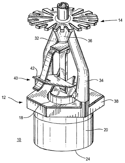
DESCRRTIUN OF DRAWINGS
FTG. I is a top elevation view of one embodiment of a low pressure, high
challenge
pendent fire protection sprurlcter ia accordance with the present invention
with a deflector
illustrated being slightly reduced in proportions;
FIG. 2 is a bottom perspective view of another embodiment of the pendent fire
protection
sprinkler of the present inventi.on;
FIG. 3 is a top plan view of the deflector of FIGS. I and 2;
FIG. 4 is a perspective view of a deflector suitable for use with an upright
sprinkler; and
FIG. 5 is a schematic view of an array of sprinklers in accordance with the
present
invention.
CA 02636610 2008-07-09
WO 2007/095245 PCT/US2007/003826
14
DETAILED DESCRIPTION OF THE PREFERRED EIVIBODIMENTS
With reference to FIG. 1, a sprinkler 10 in accordance with a preferred
embodiment of
the present invention has two main components: a frame 12 and a deflector 14.
The frame 12 is hollow and substantially tubular at its upper portion, having
an upper
inlet orifice 16 for receiving a stream of fire fighting liquid (not
illustrated) such'as water. For
convenience, the present application will refer to the liquid as water, but
any appropriate
flowable substance may be used.
The frame 12 further includes a lower outlet orifice (not visible) through
which the
stream of water may be discharged downwardly. The sprinkler 10 is of the
pendent type with the
deflector 14 positioned below the frame 12 to at least partially intercept the
stream of water to
convert the stream of water into a spray of water droplets distributed in a
predetermined pattern.
The frame 12 includes a tubular body 20 defining an internal passageway 22
having the
inlet orifice 16 at an upper inlet end 24. The lower discharge end of the
passageway 22 in the
frame 12 forms the outlet orifice. Threads 28 are provided on the outside of
the inlet end 24 to
permit the sprinkler 10 to be coupled to a drop or supply pipe (not
illustrated) for delivery thereto
of water or another fire fighting liquid. With K factors in the mid 20's to
the lower to mid 40's,
the pipe will likely be fed by a main with a nominal 3" diameter and the
sprinkler mounted on a
pipe with a nonzinal 1" diameter, thus making it less suitable for upright-
type sprinklers.
CA 02636610 2008-07-09
WO 2007/095245 PCT/US2007/003826
As shown in FIG. 1, the frame 12 further includes a yoke 30 having opposed
support
arms 32, 34 which extend generally away from the discharge end 26 of the body
20 and meet to
form a conical screw-boss or nose 36 along the central axis of the internal
passageway. The
support arms 32, 34 and the screw-boss or nose 36 support the deflector 14
positioned juxtaposed
to, facing and spaced away from the discharge end of the body 20.
W-hile two symmetrically positioned support arms are preferred, additional
support arms
may be provided, preferably symmetrically positioned around and spaced away
from the central
axis. As well, the nose 36 may be modified in shape and design to assist in
the dispersion
pattern of the water exiting the discharge end of the tubular body 20.
The frame 12 is preferably enlarged at the discharge end of the body 20 in a
circumferential boss 38, preferably hexagonally shaped to allow easy
tightening from many
angles, reducing the assembly effort.
Sprinkler 10 further includes an operating mechanism 40 for closing the
internal
passageway 22 at the outlet orifice 18 (shown in FIG. 2) to prevent the flow
of water until a fire
occurs. In one embodiment, a heat responsive trigger in the form of a
frangible glass bulb 46 is
mounted to releasably retain closure until the trigger is activated.
The bulb 46 is filled with a heat responsive liquid. During a fire, the
ambient temperature
rises, causing the liquid in the bulb 46 to expand. When the ambient
temperature reaches the
rated temperature oft.he sprinkler 10, the bulb 46 shatters. As a result, the
passageway 22 is
CA 02636610 2008-07-09
WO 2007/095245 PCT/US2007/003826
16
cleared of all sealing parts and water is discharged towards the deflector 14.
Although a
frangible bulb is illustrated, other triggering devices as are well known in
the art are also
suitable.
For example, as illustrated in FIG. 2, the operating mechanism 40 can be in
the form of a
fusible solder link 42. When the ambient temperature from a fire reaches the
rated temperature
of the sprinkler 10, the solder softens and the link separates, thereby
releasing the sealing parts
that close the outlet ortfice 18. As a result, the passageway 22 is cleared of
all the sealing parts
and water is discharged towards the deflector 14.
The deflector 14 shown in detail in FIG. 3 is preferably used with pendent
sprinklers. The
deflector is one illustrative embodiment and others will become apparent to
those skilled in the
art, without undue experimentation given the objective of having a sprinkler
which will provide,
upon actuation, a pathway for water to be directed somewhat centrally below
the sprinkler and,
as well, radially outward so that the effective radially outward area of
coverage will preferably
be in excess of 100 square feet, preferably less than 200 square feet, and
preferably in the order
of 144 square feet. Nonetheless, as will be understood by one skilled in the
art, a lesser area of
coverage, e.g., 80 square feet, may be desired for installations where a
closer arrangement (i.e.,
positioning) of sprinklers is required.
As shown in FIGS. I and 2, the deflector 14 has a generally planar annular
central section
50 having a generally circular periphery 36. A plurality of tines 52 each
extend radially
outwardly to a respective outer edge 54.. The tines 52 are spaced
circuzxiferentially.
CA 02636610 2008-07-09
WO 2007/095245 PCT/US2007/003826
17
As shown in FIG_ 3, each pair of tines define a somewhat Y shaped unit 56 with
the
embodiment in FIG. 3 having 10 such Y shaped units 56 in the array.
The solid surfaces 58 of each Y shaped unit 56 direct the flow of water
outward. The
slots or open areas- 60 providing pathways for water to be directed more
inunediately downward.
In its preferred embodiment the slots which permit the flow more directly
beneafh the deflector
are less open than, for example, a comparable deflector for a comparably sized
suppression
sprinkler. As a result, a greater proportion of the water is directed radially
outward and to a
degree, the amount of water channeled directly beneath the sprinkier head is
reduced.
FIG. 4 illustrates an embodirnent of a deflector 14 that is preferably used
with an upright
sprirWer, the body of the sprinkler generally being as disclosed hereinabove
for a pendant
sprinkler. The deflector 14 includes a generally solid annular central
section. 50 having a
generally circular periphery 36. An aperture 62-is provided in the center of
the central section 50
for attachment to the frame 12 in a conventional manner. Preferably, the
central section 50 is
somewhat concave from the perspective of the outlet orifice 18 when the
pendent 14 is attached
to the frame 12.
An annular flange 64 is integrally formed at the periphery 36 of the central
section 50.
The annu.lar flange 64 is curved or slanted in a direction somewhat norrnal to
the central section
50. The annular flange 64 includes a plurality of slots 60 which form a
plurality of spaced-apart
tines 52 that extend radially outwardly to a respective outer edge 54.
CA 02636610 2008-07-09
WO 2007/095245 PCT/US2007/003826
18
The solid surfaces of the central section 50 and the plurality of tines 58
direct tiie flow of
water downward. That is, when the upright sprinkler is activated, water flows
from the outlet
orifice 18 and is deflected downward by the concave shaped central section 50
and downward
slanting tines 52 of the deflector 14. Conversely, the slots or open areas 60
provide pathways for
water to be directed more immediately upward and outward_ In its preferred
embodiment, the
slots which permit the flow radially outward from the deflector are more open
than, for example,
a comparable deflector for a comparably sized sprinkler. Moreover, the slots
60 formed in the
annular flange 64 can also extend a dista.ace into the central section 50 (as
drawn in phantom of
FIG. 4) and/or additional slots 60 (not shown) can be formed in the central
section. As a result, a
greater proportion of the water is directed radially outward and to a degree,
the amount of water
channeled directly beneath the sprinicler head is reduced.
FIG. 5 schematically illustrates a sprinkler system incorporating a plurality
of the
individual sprinklers 10, each spaced apart by a distance of, for example, 10
to 12 feet.
The spacing is such that, given the RTI and dispersion characteristics of the
sprinkler 10,
a plume that will activate a single sprinkler will, at the same time, actuate
at least one additional
and preferably an array of 4 to 10 spriuklers at substantially the same
tiirne, and thereby provide a
combined actual delivered density (ADD) to penetrate the plume, cool the
ceiling, pre wet
adjacent areas, and more likely, directly attack the area of actual
conflagration in high ceiling
extra hazard and high piled storage occupancies. As well, the sprinklers are
capable of use at
water pressures sufficiently low as generally not to require supplemental
pumps.
CA 02636610 2008-07-09
WO 2007/095245 PCT/US2007/003826
19
Wfa.ile the disclosed apparatus has been particularly shown and described with
respect to
the preferred embodiments, it is understood by those skilled in the art that
various modifications
in form and detail may be made therein without departing from th.e scope and
spirit of the
invention. Accordingly, modifications such as those suggested above, but rtot
limited thereto are
to be considered within the scope of the invention, which is to be determined
by reference to the
appended claims.