Note: Descriptions are shown in the official language in which they were submitted.
CA 02637594 2008-07-17
-1-
SPECIFICATION
TITLE OF THE INVENTION
BASE STATION, COMMUNICATION TERMINAL,
TRANSMISSION METHOD AND RECEPTION METHOD
TECHNICAL FIELD
The present invention relates to a
technical field of radio communications. More
particularly, the present invention relates to a
base station, a communication terminal, a
transmission method, and a reception method used for
a communication system in which frequency scheduling
and multicarrier transmission are performed.
BACKGROUND ART
In this kind of technical field, it is
becoming more and more important to realize wideband
radio access for performing high speed large
capacity communication efficiently. Especially, as
for downlink channels, a multicarrier scheme, more
particularly, that is an Orthogonal Frequency
Division Multiplexing (OFDM) scheme is considered
promising from the viewpoint of performing high
speed large capacity communications while
suppressing multipath fading effectively, and the
like. Then, performing frequency scheduling is also
proposed in a next generation system in terms of
improving throughput by increasing frequency use
efficiency.
As shown in Fig.1, a frequency band that
can be used in the system is divided to a plurality
of resource blocks (divided to three blocks in the
example of the figure), and each of the resource
blocks includes one or more subcarriers. The
resource block is also called a frequency chunk. A
terminal is assigned one or more resource blocks.
In frequency scheduling, a resource block is
CA 02637594 2008-07-17
-2-
assigned to a terminal in which channel state is
good by priority according to received signal
quality or channel state information (CQI: Channel
Quality Indicator), of each of resource blocks of a
downlink pilot channel, reported from terminals, so
that transmission efficiency or throughput of the
whole system is tried to improve. When frequency
scheduling is performed, it is necessary to report
content of the scheduling to the terminal, and the
report is performed using a control channel (that
may be called L1/L2 control signaling channel,
associated control channel, low layer control
channel, or the like). In addition, a modulation
scheme (QPSK, 16QAM, 64QAM and the like, for
example) used for the scheduled resource block, a
channel coding information (channel coding rate and
the like, for example), and a hybrid automatic
retransmission request (HARQ: Hybrid Auto Repeat
ReQuest) are transmitted using the control channel.
The technique for dividing a frequency band into a
plurality of resource blocks and changing modulation
schemes for each resource block is described in the
non-patent document 1, for example.
[Non-patent document 1]
P.Chow,J.Cioffi,J.Bingham,"A Practical Discrete
Multitone Transceiver Loading Algorithm for Data
Transmission over Spectrally Shaped Channel",IEEE
Trans.Commun.vol.43,No.2/3/4,February/March/April
1995
DISCLOSURE OF THE INVENTION
PROBLEM TO BE SOLVED BY THE INVENTION
On the other hand, in a future radio
access scheme of next generation, various wide and
narrow frequency bands are prepared, so that it may
be required that a terminal can use various bands
according to locations or usages. In this case, as
CA 02637594 2008-07-17
-3-
to frequency bandwidths that the terminal can
receive, various wide and narrow frequency bands may
be prepared according to usage or price. Also in
this case, if frequency scheduling is properly
performed, improvement of frequency use efficiency
and throughput can be expected. However, since the
usable frequency bands for the existing
communication system is predicated on fixed bands,
when various wide and narrow frequency bands are
provided in the base station side and the terminal
side, a concrete method has not been established for
properly reporting content of scheduling to the
terminal or the user while permitting every
combinations.
On the other hand, if a specific resource
block common to every terminal is fixedly assigned
for a control channel, since channel states of
terminals are generally different for each resource
block, there is a fear that the control channel
cannot be properly received depending on the
terminal. In addition, when the control channel is
distributed to all resource blocks, any terminal may
receive the control channel with a certain receive
quality. But, it becomes difficult to expect
receive quality better than that. Therefore, it is
desired to transmit a control channel to terminals
with higher quality.
In addition, when adaptive modulation and
coding (AMC) control is performed in which
modulation schemes and channel coding rates are
adaptively changed, a number of symbols necessary
for transmitting the control channel is different
for each terminal. This is because an information
amount transmitted per one symbol is different
depending on combination in AMC. In addition, in
future systems, it is considered to transmit and
receive separate signals using a plurality of
CA 02637594 2008-07-17
-4-
antennas provided in each of a transmission side and
a receiving side. In this case, the before-
mentioned control information such as scheduling
information and the like may be necessary for each
of the signals communicated by each antenna.
Therefore, in this case, the number of symbols
necessary for transmitting the control channel is
different not only for each terminal, but also,
there is a possibility that it is different
according to the number of antennas used for the
terminal. When an amount of information that should
be transmitted using the control channel is
different for each terminal, for using resources
efficiently, it is necessary to use a variable
format that can flexibly support variation of the
control information amount. But, there is a fear
that signal processing load in the transmitting side
and the receiving side becomes large. In contrast,
when the format is fixed, it is necessary to reserve
a field specific for the control channel adapting to
a maximum information amount. But, by doing that,
even if the field specific for the control channel
is unoccupied, resources of that part are not used
for data transmission, so that it contradicts the
requirement of effective use of resources.
Therefore, it is desired to transmit the control
channel easily and efficiently.
The present invention is contrived for
solving at least one of the above-mentioned problems,
and the object is to provide a base station, a
communication terminal, a transmission method and a
reception method for efficiently transmitting a
control channel to various terminals in which
bandwidths by which communication can be performed
are different, in a communication system in which a
frequency band assigned to the communication system
is divided into a plurality of frequency blocks each
CA 02637594 2008-07-17
-5-
of which includes a plurality of resource blocks
each including one or more subcarriers, and a
terminal performs communication using one or more
frequency blocks.
MEANS FOR SOLVING THE PROBLEM
A base station using in an embodiment of
the present invention is used in a communication
system in which a frequency band provided to the
communication system includes a plurality of
frequency blocks wherein each of the frequency
blocks includes a plurality of resource blocks each
including one or more subcarriers. The base station
communicates with a communication terminal that uses
one or more frequency blocks. The base station
includes:
means configured to manage correspondence
relationship between bandwidths by which individual
communication terminals can perform communication
and frequency blocks to be assigned to the
communication terminals;
a frequency scheduler configured to
determine, for each frequency block, scheduling
information for assigning one or more resource
blocks to a communication terminal being in a good
channel state;
means configured to generate a control
channel including the scheduling information for
each frequency block;
multiplexing means configured to frequency
multiplexing control channels generated for each
frequency block within the frequency band provided
to the communication system; and
means configured to transmit an output
signal of the multiplexing means using a
multicarrier scheme.
A base station used in an embodiment of
CA 02637594 2008-07-17
-6-
the present invention is a base station of a
multicarrier scheme that performs frequency
scheduling in a frequency band including a plurality
of resource blocks each including one or more
subcarriers. The base station includes:
a frequency scheduler configured to
determine scheduling information for assigning one
or more resource blocks to a communication terminal
in a good channel state based on channel state
information reported from individual communication
terminals; and
means configured to perform coding and
modulation for a control channel including a non-
specific control channel to be decoded by a non-
specific communication terminal and a specific
control channel to be decoded by a specific
communication terminal to which one or more resource
blocks are assigned;
multiplexing means configured to time
multiplexing the non-specific control channel and
the specific control channel according to the
scheduling information; and
means configured to transmit an output
signal of the multiplexing means using a
multicarrier scheme.
A base station used in an embodiment of
the present invention is a base station of a
multicarrier scheme that performs frequency
scheduling in a frequency band including a plurality
of resource blocks each including one or more
subcarriers. The base station includes:
a frequency scheduler configured to
determine scheduling information for assigning one
or more resource blocks to a communication terminal
in a good channel state based on channel state
information reported from individual communication
terminals;
CA 02637594 2008-07-17
-7-
multiplexing means configured to multiplex
a control channel and a data channel according to
the scheduling information; and
means configured to transmit an output
signal of the multiplexing means using a
multicarrier scheme. A control channel to be
decoded by a specific communication terminal is
mapped over the frequency band including a plurality
of resource blocks in a distributed manner.
A base station used in an embodiment of
the present invention is a base station of a
multicarrier scheme that performs frequency
scheduling in a frequency band including a plurality
of resource blocks each including one or more
subcarriers. The base station includes:
a frequency scheduler configured to
determine scheduling information for assigning one
or more resource blocks to a communication terminal
in a good channel state based on channel state
information reported from individual communication
terminals;
multiplexing means configured to multiplex
a control channel and a data channel according to
scheduling information; and
means configured to transmit an output
signal of the multiplexing means using a
multicarrier scheme. A control channel to be
decoded by a specific communication terminal is
mapped limitedly to a resource block assigned to the
specific communication terminal.
A base station used in an embodiment of the
present invention is a base station of a
multicarrier scheme that performs frequency
scheduling in a frequency band including a plurality
of resource blocks each including one or more
subcarriers. The base station includes:
a frequency scheduler configured to
CA 02637594 2008-07-17
-8-
determine scheduling information for assigning one
or more resource blocks to a communication terminal
in a good channel state based on channel state
information reported from individual communication
terminals; and
means configured to perform coding and
modulation for a control channel including a non-
specific control channel to be decoded by a non-
specific communication terminal and a specific
control channel to be decoded by a specific
communication terminal to which one or more resource
blocks are assigned;
multiplexing means configured to time
multiplex the non-specific control channel and the
specific control channel according to the scheduling
information; and
means configured to transmit an output
signal of the multiplexing means using a
multicarrier scheme. The non-specific control
channel includes information indicating a
transmission format of the non-specific control
channel.
EFFECT OF THE INVENTION
According to the present invention, it
becomes possible to efficiently transmit a control
channel to various terminals in which bandwidths by
which communication can be performed are different,
in a communication system in which each of a
plurality of frequency blocks forming a system
frequency band includes a plurality of resource
blocks each including one or more subcarriers.
BRIEF DESCRIPTION OF THE DRAWINGS
Fig.1 is a diagram for explaining
frequency scheduling;
Fig.2 is a diagram showing a frequency
CA 02637594 2008-07-17
-9-
band used in an embodiment of the present invention;
Fig.3A shows a partial block diagram of a
base station according to an embodiment of the
present invention (1);
Fig.3B shows a partial block diagram of a
base station according to an embodiment of the
present invention (2);
Fig.4A is a diagram showing signal
processing elements on one frequency block;
Fig.4B is a diagram showing signal
processing elements on a control channel;
Fig.4C is a diagram showing signal
processing elements on a control channel;
Fig.4D is a diagram showing signal
processing elements on a control channel;
Fig.4E is a diagram showing signal
processing elements on one frequency block;
Fig.5A is a diagram showing information
item examples of control signaling channels;
Fig.5B is a diagram showing a localized
FDM scheme and a distributed FDM scheme;
Fig.5C is a diagram showing a L1/L2
control channel in which a number of symbols changes
according to a number of simultaneously multiplexed
users;
Fig.6 is a diagram showing units of error
correcting coding;
Fig.7A is a diagram showing a mapping
example of data channels and control channels;
Fig.7B is a diagram showing a mapping
example of data channels and control channels;
Fig.7C is a diagram showing format
examples of the L1/L2 control channel;
Fig.7D is a diagram showing format
examples of the L1/L2 control channel;
Fig.7E is a diagram showing mapping
examples of the L1/L2 control channel in a three
CA 02637594 2008-07-17
-10-
sector configuration;
Fig.7F is a diagram exemplary showing
multiplexing schemes of a non-specific control
channel;
Fig.7G is a diagram showing a mapping
example of data channels and control channels;
Fig.7H is a diagram showing a mapping
example of data channels and control channels;
Fig.7I is a diagram showing a mapping
example of data channels and control channels;
Fig.7J is a diagram showing a manner for
grouping users in a cell;
Fig.8A shows a partial block diagram of a
terminal used in an embodiment of the present
invention;
Fig.8B shows a partial block diagram of a
terminal used in an embodiment of the present
invention;
Fig.8C shows a block diagram related to a
reception unit of the terminal;
Fig.9 is a flowchart showing an operation
example according to an embodiment of the present
invention;
Fig.10A is a diagram showing relationship
between subjects of error check and channel coding
units;
Fig.10B is a diagram showing relationship
between subjects of error check and channel coding
units;
Fig.10C is a diagram showing relationship
between subjects of error check and channel coding
units;
Fig.10D is a diagram showing a method
example for decreasing information amount of uplink
data transmission related information;
Fig.10E is a diagram showing an operation
example when frequency hopping is performed;
CA 02637594 2008-07-17
-11-
Fig.11 is a diagram showing a flowchart of
an operation example and frequency bands of an
embodiment of the present invention;
Fig.12 is a diagram showing a flowchart
of another operation example and frequency bands of
an embodiment of the present invention;
Fig.13 is a diagram showing a manner in
which TPC is performed;
Fig.14 is a diagram showing a manner in
which AMC control is performed.
Description of reference signs
31 frequency block assignment control unit
32 frequency scheduling unit
33-x control signaling channel generation unit in
frequency block x
34-x data channel generation unit n frequency block
x
35 broadcast channel (or paging channel) generation
unit
1-x first multiplexing unit on frequency block x
37 second multiplexing unit
38 third multiplexing unit
39 other channel generation unit
40 Inverse Fast Fourier Transform unit
41 cyclic prefix adding unit
41 non-specific control channel generation unit
42 specific control channel generation unit
43 multiplexing unit
81 carrier frequency tuning unit
82 filtering unit
83 cyclic prefix removing unit
84 fast Fourier transform unit (FFT)
85 CQI measurement unit
86 broadcast channel decoding unit
87-0 non-specific control channel (part 0) decoding
unit
CA 02637594 2008-07-17
-12-
87 non-specific control channel decoding unit
88 specific control channel decoding unit
89 data channel decoding unit
PREFERRED EMBODIMENTS FOR CARRYING OUT THE INVENTION
According to an embodiment of the present
invention, frequency scheduling is performed for
each frequency, and the control channel for
reporting scheduling information is generated for
each frequency block in accordance with a minimum
bandwidth. Accordingly, the control channel can be
efficiently transmitted to various communication
terminals in which bandwidths by which communication
can be performed are different. The communication
terminal is a mobile terminal or a mobile station
typically, but it may be a fixed terminal or a fixed
station. The communication terminal may be called a
user apparatus.
The control channels generated for each
frequency block may be frequency multiplexed
according to a predetermined hopping pattern. This
can equalize communication quality among
communication terminals and among frequency blocks.
A broadcast channel may be transmitted
using a band that is a band including a center
frequency of the frequency band provided to the
communication system and that has a bandwidth
corresponding to one frequency block. This allows
any communication terminal that tries to access the
communication system to easily connect to the
communication system by receiving a signal of a
minimum bandwidth in the vicinity of the center
frequency.
A paging channel is also transmitted using
a band that is a band including a center frequency
of the frequency band provided to the communication
system and that has a bandwidth corresponding to one
CA 02637594 2008-07-17
-13-
frequency block. This makes it possible to combine
a reception band when standby and a band for
performing cell search, so that this is preferable
from the viewpoint that a number of times of
frequency tuning can be decreased as much as
possible.
From the viewpoint of using the whole
frequency band evenly, a paging channel for paging a
communication terminal may be transmitted using a
frequency block assigned to the communication
terminal.
According to an embodiment of the present
invention, the control channel may be separated to
a non-specific control channel to be decoded by a
non-specific communication terminal and a specific
control channel to be decoded by a specific
communication terminal to which one or more resource
blocks are assigned, and these channels may be coded
and modulated separately. The non-specific control
channel and the specific control channel are time
multiplexed according to scheduling information so
that the control channel is transmitted using a
multicarrier scheme. Accordingly, the control
channel can be efficiently transmitted without waste
of resources using a fixed format even though
control information amounts are different for each
communication terminal.
The non-specific control channel may be
mapped over the frequency band in a distributed
manner, and the specific control channel relating to
a specific communication terminal may be mapped
limitedly to a resource block assigned to the
specific communication terminal. While the quality
of the non-specific control channel can be kept to
be equal to or greater than a certain level over the
whole users, the quality of the specific control
channel can be made good. This is because the
CA 02637594 2008-07-17
-14-
specific control channel is mapped to a resource
block in a good channel state for each of the
specific communication terminals.
A downlink pilot channel may be also
mapped over a plurality of resource blocks assigned
to a plurality of communication terminals in a
distributed manner. By mapping the pilot channel
over a wide band, channel estimation accuracy and
the like can be improved.
According to an embodiment of the present
invention, from the viewpoint of maintaining or
improving reception quality of the control channel
including the non-specific and specific control
channels, transmission power control is performed on
the non-specific control channel, and one or both of
transmission power control and adaptive modulation
and coding control are performed on the specific
control channel.
Transmission power control for the non-
specific control channel may be performed such that
the specific communication terminal to which a
resource block is assigned can receive the non-
specific control channel with high quality. This is
because, although every user or communication
terminal that received the non-specific control
channel is obliged to try demodulation, it is only
necessary that the user to which a resource block is
actually assigned succeeds demodulation eventually.
The non-specific control channel may
include information of one or both of a modulation
scheme and a coding scheme applied to the specific
control channel. Since the combination of the
modulation scheme and the coding scheme for the non-
specific control channel is fixed, the user to which
the resource block is assigned can obtain the
modulation scheme and the coding scheme and the like
for the specific control channel by demodulating the
CA 02637594 2008-07-17
-15-
non-specific control channel. By this method,
adaptive modulation and coding control can be
performed on the part of the specific control
channel in the control channel, so that reception
quality of the part can be improved.
When the transmission power control and
the adaptive modulation and coding control are
performed for the control channel, a total number of
combinations of modulation schemes and coding
schemes for the specific control channel may be
prepared to be less than a total number of
combinations of modulation schemes and coding
schemes for the shared data channel. This is
because, although required quality can be obtained
by the adaptive modulation and coding control,
required quality can be obtained by performing
transmission power control.
[Embodiment 1]
Fig.2 shows a frequency band used in an
embodiment of the present invention. Although
concrete numeric values are used for the sake of
description, the values are merely examples, and
various values may be used. The frequency band
(whole transmission band) provided for the
communication system has a bandwidth of 20 MHz as an
example. The whole transmission band includes four
frequency blocks 1-4, and each of the frequency
blocks includes a plurality of resource blocks each
including one or more subcarriers. The example
shown in the figure schematically shows that each
frequency block includes many subcarriers. In the
present embodiment, four types of 5 MHz, 10 MHz, 15
MHz and 20 MHz are prepared as bandwidths for
performing communication. A terminal uses one or
more frequency blocks to perform communication using
one of the four bandwidths. A terminal performing
communication in the communication system may be
CA 02637594 2008-07-17
-16-
able to perform communication by using any of the
four bands, or may be able to perform communication
by using only some of the bandwidths. However, it
is necessary to be able to perform communication
using at least 5 MHz band. Or, instead of preparing
such a plurality of kinds of bands, a standard may
be defined such that any communication terminal can
perform communication in the whole of the system
bandwidth. For providing more general description,
a case in which choices of four kinds of bandwidths
are prepared in the following embodiments is
described. However, it can be understood that the
present invention is applicable irrespective of
presence or absence of such choices of the
bandwidths.
In the present embodiment, a control
channel (L1/L2 control signaling channel or low
layer control channel) for reporting scheduling
information of a data channel (shared data channel)
is formed by the minimum bandwidth (5 MHz), and the
control channel is independently provided for each
frequency block. For example, when a terminal
performing communication using a bandwidth of 5 MHz
performs communication using a frequency block 1,
the terminal receives a control channel prepared for
the frequency block 1 so that the terminal can
obtain content of scheduling. Which frequency block
the terminal can use for communication may be
reported beforehand using a broadcast channel, for
example. In addition, after starting communication,
a frequency block to be used may be changed. When a
terminal performing communication using a bandwidth
of 10 MHz performs communication using frequency
blocks 1 and 2, the terminal uses adjacent two
frequency blocks, and receives both control channels
prepared for the frequency blocks 1 and 2 so that
the terminal can obtain content of scheduling over a
CA 02637594 2008-07-17
-17-
range of 10 MHz. A terminal that performs
communication using a bandwidth of 15 MHz uses
adjacent three frequency blocks, and when the
terminal performs communication using frequency
blocks 1, 2 and 3, the terminal receives all control
channels prepared for the frequency blocks 1, 2 and
3 so that the terminal can obtain content of
scheduling over the range of 15 MHz. A terminal
that performs communication using a bandwidth of 20
MHz receives all control channels provided for all
frequency blocks so that the terminal can obtain
content of scheduling over the range of 20 MHz.
In the figure, four discrete blocks are
shown in a frequency block with respect to the
control channel. This shows that the control
channel is distributed and mapped into a plurality
of resource blocks in the frequency block. A
concrete mapping example of the control channel is
described later.
Fig.3A shows a partial block diagram of a
base station according to an embodiment of the
present invention. Fig.3A shows a frequency block
assignment control unit 31, a frequency scheduling
unit 32, a control signaling channel generation unit
33-1 and a data channel generation unit 34-1 in the
frequency block 1, ..., a control signaling channel
generation unit 33-M and a data channel generation
unit 34-M in the frequency block M, a broadcast
channel (or paging channel) generation unit 35, a
first multiplexing unit 1-1 for the frequency block
1, ..., a first multiplexing unit 1-M for the
frequency block M, a second multiplexing unit 37, a
third multiplexing unit 38, an other channel
generation unit 39, an Inverse Fast Fourier
Transform unit 40 (IFFT) and a cyclic prefix adding
unit 41.
Based on information relating to a maximum
CA 02637594 2008-07-17
-18-
bandwidth by which communication can be performed
reported from a terminal (that may be a mobile
terminal or a fixed terminal), the frequency block
assignment control unit 31 checks a frequency block
to be used by the terminal. The frequency block
assignment control unit 31 manages correspondence
relationship between individual terminals and
frequency blocks, and reports the content to the
frequency scheduling unit 32. Which frequency block
can be used for communication by a terminal that can
perform communication using a bandwidth may be
reported beforehand using a broadcast channel. For
example, the broadcast channel may permit a user
performing communication using the bandwidth of 5
MHz to use any one band of frequency blocks 1, 2, 3
and 4, or use may be limited to any of these. In
addition, a user that performs communication using a
bandwidth of 10 MHz is permitted to use a
combination of adjacent two frequency blocks such as
frequency blocks (1, 2), (2, 3) or (3, 4). All of
these may be permitted to use, or use may be limited
to any one of the combinations. A user that
performs communication using a bandwidth of 15 MHz
is permitted to use a combination of adjacent three
frequency blocks such as frequency blocks (1, 2, 3)
or (2, 3, 4). Both of them may be permitted to use,
or use may be limited to any one of the combinations.
A user that performs communication using a bandwidth
of 20 MHz is permitted to use all of the frequency
blocks. As described later, a usable frequency
block may be changed after starting communication
according to a predetermined frequency hopping
pattern.
The frequency scheduling unit 32 performs
frequency scheduling in each of the plurality of
frequency blocks. Frequency scheduling in one
frequency block determines scheduling information so
CA 02637594 2008-07-17
-19-
as to assign a resource block preferentially to a
terminal having a good channel state based on
channel state information CQI of each resource block
reported from terminals.
The control signaling channel generation
unit 33-1 in the frequency block 1 uses resource
blocks only in the frequency block 1 to configure a
control signaling channel for reporting scheduling
information in the frequency block 1 to terminals.
Similarly, as to other frequency block, a control
signaling channel for reporting scheduling
information in the frequency block to terminals is
configured using resource blocks only in the
frequency block.
The data channel generation unit 34-1 in
the frequency block 1 generates a data channel to be
transmitted using one or more resource blocks in the
frequency block 1. Since the frequency block 1 may
be shared by one or more terminals (users), N data
channel generation units 1-1 - N are prepared in the
example shown in the figure. Similarly, as to other
frequency block, data channels of terminals that
share the frequency block are generated.
A first multiplexing unit 1-1 for the
frequency block 1 multiplexes signals relating to
the frequency block 1. This multiplexing at least
includes frequency multiplexing. How the control
signaling channel and the data channel are
multiplexed is described later. Similarly, other
first multiplexing unit 1-x multiplexes the control
signaling channel and the data channel transmitted
using the frequency block x.
The second multiplexing unit 37 performs
operation for changing position relationship among
the various multiplexing units 1-x (x=1, M) on
the frequency axis according to a predetermined
hopping pattern. This function is described in the
CA 02637594 2008-07-17
-20-
second embodiment.
The broadcast channel (or paging channel)
generation unit 35 generates broadcast information
such as office data to be reported to terminals
under the base station. Information indicating
relationship between a maximum frequency band by
which the terminal can perform communication and a
frequency block that the terminal can use may be
included in control information. When the usable
frequency block variously changes, the broadcast
information may include information specifying a
hopping pattern that indicates how the frequency
block changes. By the way, the paging channel may
be transmitted using a same band as the broadcast
channel, or may be transmitted using a frequency
block used in each terminal.
Other channel generation unit 39 generates
a channel other than the control signaling channel
and the data channel. For example, the other
channel generation unit 39 generates a pilot channel.
A pilot channel or a pilot signal is some sort of
proper signal that is known in the transmission side
and the reception side, and it may be referred to as
a reference signal, a reference signal, a known
signal, a training signal and the like.
The third multiplexing unit 38 multiplexes
the control signaling channels and the data channels
of each frequency block, and, the broadcast channel
and/or other channel as necessary.
The Inverse fast Fourier transform unit 40
performs inverse fast Fourier transform on a signal
output from the third multiplexing unit 38 to
perform modulation based on the OFDM scheme.
The cyclic prefix (CP) adding unit 41 adds
a guard interval to a symbol after modulation of the
OFDM scheme to generate a transmission symbol. The
transmission symbol may be generated by adding a
CA 02637594 2008-07-17
-21-
series of data at the end (or top) of the OFDM
symbol to the top (or end).
Fig.3B shows elements next to the CP
adding unit 41 shown in Fig.3A. As shown in the
figure, the symbol to which the guard interval is
added is amplified to a proper power by a power
amplifier after processes of digital analog
conversion, frequency conversion and band limitation
and the like by an RF transmission circuit, and the
signal is transmitted via a duplexer and a transmit
and receive antenna.
Although not essential for the present
invention, antenna diversity reception is performed
by two antennas when performing reception in the
present embodiment. An uplink signal received by
the two antennas are supplied to an uplink signal
reception unit.
Fig.4A shows signal processing elements on
one frequency block (x-th frequency block). "x" is
an integer equal to or greater than 1 and equal to
or less than M. Generally, the figure shows a
control signaling channel generation unit 33-x and a
data channel generation unit 34-x relating to the
frequency block x, multiplexing units 43-A and B,
and a multiplexing unit 1-x. The control signaling
channel generation unit 33-x includes a non-specific
control channel generation unit 41 and one or more
specific control channel generation units 42-A,
B,
In the control signaling channel, the non-
specific control channel generation unit 41 performs
channel coding and multilevel modulation on a part
of the non-specific control channel (that may be
called non-specific control information) that every
terminal using the frequency block should decode and
demodulate, and outputs it.
Each of the specific control channel
CA 02637594 2008-07-17
-22-
generation units 42-A, B, ... performs channel
coding and multilevel modulation on a part of the
specific control channel (that may be called
specific control information), in the control
signaling channel, that a terminal to which one or
more resource blocks is assigned in the frequency
block should decode and demodulate, and outputs it.
The data channel generation units x-A,
B, ... perform channel coding and multilevel
modulation on data channels addressed to individual
terminals A, B, ..., respectively. Information on
the channel coding and multilevel modulation is
included in the specific control channel.
The multiplexing unit (43-A, B, ...)
associates the specific control channel and the data
channel to a resource block for each terminal to
which the resource block is assigned.
As mentioned above, coding (and
modulation) for the non-specific control channel is
performed in the non-specific control channel
generation unit 41, and coding (and modulation) for
the specific control channel is performed in the
specific control channel generation units 42-A,
B,...., individually. Therefore, in the present
embodiment, as shown in Fig.6 conceptually, the non-
specific control channel includes pieces of
information of all users to whom the frequency block
x is assigned, and these pieces of information
become a subject for error correcting coding on the
whole.
In another embodiment, the non-specific
control channel may be also error correcting coded
for each user. In this case, since each user cannot
uniquely specify which block includes its own
information in blocks that are individually error
correcting coded, it is necessary to decode all
blocks. In this another embodiment, since coding
CA 02637594 2008-07-17
-23-
processing is closed for each user, it is relatively
easy to add and change users. Each user needs to
decode and modulate non-specific control channels of
all users.
On the other hand, the specific control
channel only includes information on a user to which
a resource block is actually assigned, so that error
correcting coding is performed for each user. Which
user is assigned a resource block is revealed by
decoding and modulating the non-specific control
channel. Therefore, it is not necessary that all
user decode the specific control channel, and it is
only necessary that a user to which a resource block
is assigned perform decoding. By the way, a channel
coding rate and a modulation scheme for the specific
control channel are changed as necessary during
communication, but a channel coding rate and a
modulation scheme for the non-specific control
channel may be fixed. However, it is desirable to
perform transmission power control (TPC) for
ensuring signal quality equal to or greater than a
given level. The specific control channel is
transmitted using a good resource block after error
correcting coding is performed. Therefore, downlink
data amount may be decreased to some extent by
performing puncturing.
Fig.5A shows an example of types and
information items of downlink control signaling
channels. The downlink control signaling channels
include a broadcast channel (BCH), an individual L3
signaling channel (upper layer control channel or
high layer control channel) and a L1/L2 control
channel (low layer control channel). The L1/L2
control channel may include not only information for
downlink data transmission but also information for
uplink data transmission. In the following,
outlines of information items transmitted by each
CA 02637594 2008-07-17
-24-
channel are described.
(Broadcast channel)
The broadcast channel is used for
reporting unchanging information or information
changing at a low speed in a cell to a communication
terminal (that may be a mobile terminal or a fixed
terminal, or may be called a user apparatus). For
example, information that may change in a period of
about 1000ms (1 second) may be reported as broadcast
information. The broadcast information may include
a transmission format of a downlink L1/L2 control
channel, a maximum number of users assigned
simultaneously, resource block placement information
and MIMO scheme information.
The transmission format is specified by a
data modulation scheme and a channel coding rate.
Instead of the channel coding rate, data size may be
reported. This is because the channel coding rate
can be uniquely derived from the data modulation
scheme and the data size.
The maximum number of simultaneously
assigned users indicates a maximum number that can
be multiplexed in 1TTI using one or more of FDM, CDM
and TDM. The number may be the same or may be
different between the uplink channel and the
downlink channel.
The resource block placement information
is information for specifying positions of resource
blocks on frequency and time axes used in the cell.
In the present embodiment, as the frequency division
multiplex (FDM) scheme, two kinds that are a
localized FDM scheme and a distributed FDM scheme
can be used. In the localized FDM scheme,
continuous bands are locally assigned to a user in a
good channel state on the frequency axis on a
priority basis. This scheme is advantageous for
communication of a user of small mobility, data
CA 02637594 2008-07-17
-25-
transmission of high quality and high capacity, and
the like. In the distributed FDM scheme, a downlink
signal is generated so as to intermittently include
a plurality of frequency components ranging over a
wide band. This scheme is advantageous for
communication of a user of large mobility, periodic
data transmission of small data size such as voice
packet (VoIP), and the like. Whether any scheme is
used, resource assignment for frequency resources is
performed according to information specifying
continuous bands or a plurality of discrete
frequency components.
As shown in the upper side of Fig.5B, when
a resource is specified by "4" in the localized FDM
scheme, for example, a resource of the physical
resource block number 4 is used. In the distributed
FDM scheme shown in the lower side of Fig.5B, when a
resource is specified by "4", two left halves of
physical resource blocks 2 and 8 are used. In the
example shown in the figure, one physical resource
block is divided into two. Numbering and the number
of divisions in the distributed FDM scheme may
different for each cell. Thus, resource block
placement information is reported to communication
terminals in the cell by the broadcast channel.
When a plurality of antennas are provided
in a base station, MIMO scheme information indicates
which is performed among a single user MIMO (SU-
MIMO:Single User - Multi Input Multi Output) scheme
or a multi user MIMO (MU ¨MIMO:Multi - User MIMO)
scheme. The SU-MINO scheme is a scheme for
communicating with one communication terminal having
a plurality of antennas, and the MU-MIMO scheme is a
scheme for communicating with a plurality of
communication terminals each having one antenna
simultaneously.
(Individual L3 signaling channel)
CA 02637594 2008-07-17
-26-
The individual L3 signaling channel is
also used for reporting, to a communication terminal,
information that changes at low speed such as in a
period of 1000ms, for example. Although the
broadcast channel is sent to all communication
terminals in the cell, the individual L3 signaling
channel is sent only to a specific communication
terminal. The individual L3 signaling channel
includes a type of the FDM scheme and persistent
scheduling information. The individual L3 signaling
channel may be also classified to the specific
control channel.
The type of the FDM scheme specifies which
of the localized FDM scheme and the distribute FDM
scheme is used for multiplexing the specified
individual communication terminals.
The persistent scheduling information
specifies, when persistent scheduling is performed,
a transmission format (data modulation scheme and
channel coding rate) of uplink or downlink data
channel, a resource block to be used, and the like.
(L1/L2 control channel)
The downlink L1/L2 control channel may
include not only information related to downlink
data transmission but also information related to
uplink data transmission. The former can be
classified into part 0, part 1, part 2a and part 2b.
The part 1 and the part 2a can be classified as the
non-specific control channel, and the part 2b is
classified as the specific control channel.
(Part 0)
Part 0 includes information indicating a
transmission format of the L1/L2 control channel
(modulation scheme and channel coding rate, and a
number of simultaneously assigned users or a number
of the whole control bits). When the transmission
format of the L1/L2 control channel is reported by
CA 02637594 2008-07-17
-27-
the broadcast channel, part 0 may include the number
of simultaneously assigned users (or the number of
the whole control bits).
A number of symbols necessary for L1/L2
control channel depends on the number of
simultaneously multiplexed users and reception
quality of multiplexed users. As shown in the left
side of Fig.5C, the number of symbols of the L1/L2
control channel is set to be large enough typically.
When changing the number of symbols, it can be
controlled in a period of about 1000 ms (1 second),
for example, according to the transmission format of
the L1/L2 control channel reported by the broadcast
channel. However, when the number of the
simultaneously multiplexed users is small as shown
in the right side of Fig.5C, the number of symbols
necessary for the control channel becomes small.
Therefore, when the number of the simultaneously
assigned users and the reception quality of the
multiplexed users change in a short period, there is
a case in which waste occurs in the L1/L2 control
channel that is prepared large enough.
To decrease the waste of the L1/L2 control
channel, the modulation scheme, the channel coding
rate, and the number of simultaneously assigned
users (or the number of the whole control bits) may
be reported in the L1/L2 control channel. By
reporting the modulation scheme and the channel
coding rate in the L1/L2 control channel, the
modulation scheme and the channel coding rate can be
changed with a shorter period than that in reporting
by the broadcast channel.
(Part 1)
Part 1 includes a paging indicator (PI).
Each communication terminal demodulates the paging
indicator so as to be able to check whether paging
for the own terminal is performed.
CA 02637594 2008-07-17
-28-
(Part 2a)
Part 2a includes resource assignment
information of a downlink data channel, assigned
time length, and MIMO information.
The resource assignment information of the
downlink data channel =specifies a resource block
including the downlink data channel. Various
methods known in this technical field can be used
for specifying the resource block. For example, bit
map scheme, tree branching number scheme and the
like may be used.
The assignment time length indicates how
long the downlink data channel is continuously
transmitted. Changing the resource assignment
content most frequently corresponds to changing it
every TTI. From a viewpoint to decrease overhead,
the data channel may be transmitted with same
resource assignment content over a plurality of TTIs.
The MIMO information specifies, when the
MIMO scheme is used for communication, a number of
antennas, a number of streams, and the like. The
number of streams may be called a number of
information series.
By the way, although it is not essential
that the part 2a include user identification
information, the whole or a part of it may be
included.
(Part 2b)
Part 2b includes precoding information
when the MIMO scheme is used, transmission format of
the downlink data channel, hybrid retransmission
control (HARQ) information and CRC information.
The precoding information when the MIMO
scheme is used specifies weighting coefficients
applied to each of a plurality of antennas. By
adjusting the weighting coefficients applied to each
antenna, directivity of a communication signal is
CA 02637594 2008-07-17
-29-
adjusted.
The transmission format of the downlink
data channel is specified by the data modulation
scheme and the channel coding rate. Instead of the
channel coding rate, data size or payload size may
be reported. This is because the channel coding
rate can be uniquely derived from the data
modulation scheme and the data size.
The hybrid retransmission control (HARQ:
Hybrid Automatic Repeat Request) information
includes information necessary for retransmission
control for downlink packets. More particularly,
the retransmission control information includes
process number, redundancy version information
indicating packet combining method, and new data
indicator for distinguishing between a new packet
and a retransmission packet.
The CRC information indicates, when a
cyclic redundancy check method is used for error
detection, CRC detection bit in which user
identification information (UE-ID) is convoluted.
Information related to uplink data
transmission can be classified into 4 types from
part 1 to part 4 as follows. Although these pieces
of information may be classified to the non-specific
control channel in principle, they may be
transmitted as a specific control channel for a
communication terminal to which resource is assigned
for a downlink data channel.
(Part 1)
Part 1 includes transmission confirmation
information for a past uplink data channel. The
transmission confirmation information indicates
acknowledgment (ACK) indicating that there is no
error in the packet or that there is an error but it
is in a permissible range, or indicates negative
acknowledgment (NACK) indicating that there is an
CA 02637594 2008-07-17
-30-
error exceeding a permissible range in a packet.
(Part 2)
Part 2 includes resource assignment
information for a future uplink data channel,
transmission format of the uplink data channel,
transmission power information and CRC information.
The resource assignment information
specifies a resource block that can be used for
transmitting an uplink data channel. For specifying
the resource block, various methods that are known
in this technical field can be used. For example,
bitmap scheme, tree branching number scheme, and the
like may be used.
The transmission format of the uplink data
channel is specified by the data modulation scheme
and the channel coding rate. Instead of the channel
coding rate, data size or payload size may be
reported. This is because the channel coding rate
can be uniquely derived from the data modulation
scheme and the data size.
The transmission power information
indicates how large a power by which the uplink data
channel should be transmitted is.
The CRC information indicates, when a
cyclic redundancy check method is used for error
detection, CRC detection bit in which user
identification information (UE-ID) is convoluted.
By the way, in a response signal (downlink L1/L2
control channel) for a random access channel (RACH),
a random ID of RACH preamble may be used as UE-ID.
(Part 3)
In part 3, a transmission timing control
bit is included. This is a control bit for
synchronizing the communication terminals in a cell.
(Part 4)
Part 4 includes transmission power
information on transmission power of a communication
CA 02637594 2008-07-17
-31-
terminal. This information indicates how large is a
power which the communication terminal, to which a
resource is not assigned for transmitting uplink
data channel, should use for transmitting an uplink
control channel for reporting CQI of a downlink
channel, for example.
Similarly to Fig.4A, Figh.4E shows signal
processing elements on one frequency block. But, it
appears different from Fig.4A in that it concretely
shows respective pieces of control information. In
Figs.4A and 4E, same reference symbols indicate same
elements. In the figure, "mapping within resource
block" indicates that mapping is performed being
limited to one or more resource blocks assigned to a
specific communication terminal. "Mapping outside
resource block" indicates that mapping is performed
over the whole region of the frequency block
including many resource blocks. Information (parts
1-4) related to uplink data transmission in the
L1/L2 control channel is transmitted, when a
resource is assigned for a downlink data channel,
using the resource as a specific control channel,
and the information is transmitted, when the
resource is not assigned, over the whole frequency
block as a non-specific control channel.
Fig.7A shows a mapping example of data
channels and control channels. The mapping example
shown in the figure is for one frequency block and
for one subframe, and generally corresponds to
output content of the first multiplexing unit 1-x
(pilot channel and the like is multiplexed by the
third multiplexing unit 38). One subframe may
correspond to one transmission time interval (TTI),
or correspond to a plurality of TTIs, for example.
In the example shown in the figure, the frequency
block includes seven resource blocks RB1-7. The
seven resource blocks are assigned to terminals
CA 02637594 2008-07-17
-32-
having a good channel state by the frequency
scheduling unit 32 shown in Fig.3A.
In general, the non-specific control
channel and the like, the pilot channel and the like,
and the data channel and the like are time
multiplexed. The non-specific control channel is
mapped all over the frequency block in a distributed
manner. That is, the non-specific control channel
is distributed all over the band occupied by seven
resource blocks. In the example shown in the figure,
the non-specific control channel and other control
channels (excluding specific control channel) are
frequency multiplexed. Other channels may include a
synchronization channel and the like, for example
(the non-specific control channel may be defined so
as to include the synchronization channel and the
like without differentiating between the non-
specific control channel and the other control
channels). In the example shown in the figure, the
non-specific control channel and the other control
channel are frequency multiplexed such that each
includes a plurality of frequency components that
are arranged at certain intervals. Such
multiplexing scheme is called distributed frequency
division multiplex (FDM) scheme. The intervals
between the frequency components may be the same or
may be different. In any case, it is necessary that
the non-specific control channel is distributed
over the whole range of one frequency block.
In the example shown in the figure, a
pilot channel and the like is also mapped over the
whole range of the frequency block. From the
viewpoint of correctly performing channel estimation
and the like for various frequency components, it is
desirable that the pilot channel is mapped over a
wide range as shown in the figure.
In the example shown in the figure,
CA 02637594 2008-07-17
-33-
resource blocks RB1, RB2 and RB4 are assigned to a
user 1 (UE1), resource blocks R33, RB5 and RB6 are
assigned to a user 2 (UE2), and a resource block RB7
is assigned to a user 3 (UE3). As mentioned above,
such assignment information is included in the non-
specific control channel. In addition, a specific
control channel on the user 1 is mapped to the head
of the resource block RB1 in the resource blocks
assigned to the user 1. A specific control channel
on the user 2 is mapped to the head of the resource
block RB3 in the resource blocks assigned to the
user 2. A specific control channel on the user 3 is
mapped to the head of the resource block RB7 in the
resource block assigned to the user 3. In the
figure, it should be noted that sizes occupied by
the specific control channel of the users 1, 2 and 3
are shown to be uneven. This indicates that
information amount of the specific control channel
may different according to users. The specific
control channel is locally mapped limitedly to a
resource block assigned to the data channel. In
this point, this scheme is different from the
distributed FDM in which mapping is performed over
various resource blocks in a distributed manner.
Such a mapping scheme is also called a localized
frequency division multiplexing (localized FDM).
Fig.7B shows another mapping example of
the non-specific control channel. Although the
specific control channel of the user 1 (UE1) is
mapped only to one resource block RB1 in Fig.7A, it
is discretely mapped over the whole of the resource
blocks RB1, RB2 and RB4 (the whole of the resource
blocks assigned to user 1) in a distributed manner
using the distributed FDM scheme. In addition, the
specific control channel on the user 2 (UE2) is also
different from the case shown in Fig.7A, and it is
mapped over the whole of the resource blocks RB3,
CA 02637594 2008-07-17
-34-
RB5 and RB6. The specific control channel and the
shared data channel of the user 2 are time division
multiplexed. Accordingly, the specific control
channel and the shared data channel of each user may
be multiplexed using time division multiplexing
(TDM) scheme and/or frequency division multiplexing
scheme (including localized FDM scheme and
distributed FDM scheme) in all or a part of one or
more resource blocks assigned to the user. By
mapping the specific control channel over equal to
or greater than two resource blocks, frequency
diversity effect can be expected also for the
specific control channel, so that signal quality of
the specific control channel can be further improved.
Next, concrete formats of the part 0 in
the L1/L2 control channel are described.
Fig.7C is an example showing formats of
the L1/L2 control channel when reporting a number of
symbols (or simultaneously assigned user number) of
the L1/L2 control channel. When the communication
terminal uses a modulation scheme and a coding rate
(MCS: Modulation and Coding Scheme) reported by the
broadcast channel, the number of symbols necessary
for the L1/L2 control channel changes according to
the number of simultaneously assigned users. For
identifying it, control bits (two bits in Fig.7C)
are provided as information of the part 0 of the
L1/L2 control channel. For example, by reporting
control bits of 00 as information of the part 0, for
example, the communication terminal can ascertain
that the number of symbols of the L1/L2 control
channel is 100 by decoding the control bits. By the
way, the head two bits in Fig.7C corresponds to the
part 0, and variable control channel correspond to
the non-specific control channel (corresponding to
part 1 and part 2a in the case of downlink). In
addition, although MCS is reported by the broadcast
CA 02637594 2008-07-17
-35-
channel in Fig.7C, MCS may be reported by a L3
signaling channel.
Fig.7D is an example showing a format of
the L1/L2 control channel when the number of
simultaneously assigned users of each MCS is
reported by part 0. When using a proper MCS from
predetermined kinds of MCSes according to reception
quality of the communication terminal, the number of
symbols necessary for the L1/L2 control channel
changes according to the reception quality of the
communication terminal. For identifying this,
control bits (eight bits in Fig.7D) is provided as
information of part 0 of the L1/L2 control channel.
Fig.7D shows a case, as an example, in which there
are four kinds of MCSes and a maximum value of the
number of simultaneously assigned users of each MCS
is three. Since the number of simultaneously
assigned users is 0-3, this information can be
represented by two bits (00=0 user, 01=1 user, 10=2
users, 11=3 users). Since two bits are necessary
for each MCS, part 0 becomes eight bits in this case.
For example, by reporting control bits of 01100001
as information of the part 0, the communication
terminal can ascertain control information (part 2a
in the case of downlink) according to the own
reception quality based on the control bits.
Fig.7E is an example showing mapping of
information bits (part 0) in the L1/L2 control
channel in the case of three sector configuration.
In the case of three sector configuration, three
kinds of patterns may be prepared for transmitting
the information bits (part 0) indicating a
transmission format of the L1/L2 control channel,
and assigned to each sector such that the patterns
do not overlap in the frequency domain. By
selecting a pattern such that transmission patterns
in adjacent sectors (or cells) are different with
CA 02637594 2008-07-17
-36-
each order, effect of interference coordination can
be obtained.
Fig.7F shows various examples of
multiplexing methods. Although various non-specific
control channels are multiplexed using the
distributed FDM scheme in the above-mentioned
examples, various proper multiplexing methods such
as code division multiplexing scheme and time
division multiplexing (TDM) scheme may be used.
Fig.7F(1) shows a case in which multiplexing is
performed by the distributed FDM scheme. By using
numbers 1, 2, 3 and 4 specifying a plurality of
discrete frequency components, signals of each user
can be properly orthogonalized. However, it is not
necessary to be arranged regularly like this example.
In addition, by using different rules between
adjacent cells, interference amount when performing
transmission power control can be randomized.
Fig.7F(2) shows a case in which multiplexing is
performed by code division multiplexing (CDM) scheme.
By using code 1, 2, 3 and 4, signals of each user
can be properly orthogonalized. Fig.7F(3) shows a
case when the user multiplexing number changes to
three in the distributed FDM scheme. By re-defining
the numbers 1, 2 and 3 for specifying a plurality of
discrete frequency components, signals of each user
can be properly orthogonalized. When the number of
simultaneously assigned users is less than the
maximum number, as shown in Fig.7F(4), the base
station may increase transmission power of the
downlink control channel. In addition, hybrid of
CDM and FDM can be applied.
Fig.8A shows a partial block diagram of a
mobile terminal used in an embodiment of the present
invention. Fig.8A shows a carrier frequency tuning
unit 81, a filtering unit 82, a cyclic prefix (CP)
removing unit 83, a fast Fourier transform unit
CA 02637594 2008-07-17
-37-
(FFT) 84, a CQI measurement unit 85, a broadcast
channel (or paging channel) decoding unit 86, a non-
specific control channel (part 0) decoding unit 87-0,
a non-specific control channel decoding unit 87, a
specific control channel decoding unit 88 and a data
channel decoding unit 89.
The carrier frequency tuning unit 81
properly adjusts a center frequency of a reception
band so as to be able to receive a signal of a
frequency block assigned to the terminal.
The filtering unit 82 filters a received
signal.
The cyclic prefix removing unit 83 removes
guard interval from a received signal to extract an
effective symbol part from a received symbol.
The fast Fourier transform unit (FFT)
performs fast Fourier transform on information
included in the effective symbol to perform
demodulation of the OFDM scheme.
The CQI measurement unit 85 measures a
received power level of the pilot channel included
in the received signal to feed the measurement
result back to the base station as channel state
information CQI. CQI is performed for each of all
resource blocks in the frequency block, and all of
them are reported to the base station.
The broadcast channel (or paging channel)
decoding unit 86 decodes the broadcast channel.
When the paging channel is included, it is also
decoded.
The non-specific control channel (part 0)
decoding unit 87-0 decodes information of part 0 in
the L1/L2 control channel. By the part 0, it
becomes possible to recognize a transmission format
of the non-specific control channel.
The non-specific control channel decoding
unit 87 decodes the non-specific control channel
CA 02637594 2008-07-17
-38-
included in the received signal to extract
scheduling information. The scheduling information
includes information indicating whether a resource
block is assigned to a shared data channel addressed
to the terminal, and information indicating a
resource block number when it is assigned, and the
like.
The specific control channel decoding unit
88 decodes a specific control channel included ion
the received signal. The specific control channel
includes information of data modulation, channel
coding rate, and HARQ on the shared data channel.
The data channel decoding unit 89 decodes
the shared data channel included in the received
signal based on the information extracted from the
specific control channel. According to the decoding
result, acknowledgement (ACK) or negative
acknowledgement (NACK) may be reported to the base
station.
Fig.8B shows a partial block diagram of
the mobile terminal like Fig.8A, but, Fig.8B looks
different from Fig.8A in that each pieces of control
information are concretely shown. Same reference
symbols indicate same elements in Fig.8A and Fig.8B.
In the figure, "demapping within resource block"
means extracting information that is mapped
limitedly to one or more resource blocks assigned to
a specific communication terminal. "Demapping
outside resource block" means extracting information
that is mapped over the whole of the frequency block
including many resource blocks.
Fig.8C shows elements related to a
reception unit of Fig.8A. Although not essential
for the present invention, in the present embodiment,
antenna diversity reception using two antennas is
performed when performing reception. Downlink
signals received by two antennas are supplied to RF
CA 02637594 2008-07-17
-39-
reception circuits (81, 82) respectively, guard
interval (cyclic prefix) is removed (83), and fast
Fourier transform is performed (84). Signals
received by each antenna are combined by an antenna
diversity combining unit. A signal after combining
is supplied to each decoding unit shown in Fig.8A or
to a separation unit shown in Fig.8B.
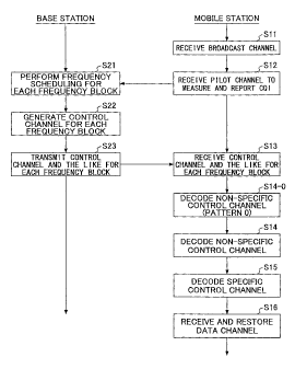
Fig.9 is a flowchart showing an operation
example according to an embodiment of the present
invention. As an example, assuming that a user
having a mobile terminal UE1 that can perform
communication using a bandwidth of 10 MHz enters a
cell or a sector in which communication is performed
using a bandwidth of 20MHz. It is assumed that the
minimum frequency band of the communication system
is 5 MHz, and that the whole band is divided into
four frequency blocks 1-4 as shown in Fig.2.
In step Sll, the terminal UE1 receives a
broadcast channel from the base station, and checks
which frequency block the own terminal can use. The
broadcast channel may be transmitted using a band of
5MHz including a center frequency of the whole band
of 20MHz. Accordingly, any terminals in which
bandwidths that can be received are different can
receive the broadcast channel easily. The broadcast
channel permit the user that performs communication
using the bandwidth of 10 MHz to use a combination
of two adjacent frequency blocks such as frequency
blocks (I, 2), (2, 3) or (3, 4). All of these may
be permitted to use, or use may be restricted to any
of the combinations. As an example, it is assumed
that frequency blocks 2 and 3 are permitted to use.
In step S12, the terminal UE1 receives a
downlink pilot channel to measure received signal
quality for the frequency blocks 2 and 3. The
measurement is performed for each of the many
resource blocks included in each frequency block, so
CA 02637594 2008-07-17
-40-
that all of these are reported to the base station
as channel state information CQI.
In step S21, the base station performs
frequency scheduling for each frequency block based
on the channel state information CQI reported from
the terminal UE1 and other terminals. It is checked
and managed by the frequency block assignment
control unit (31 in Fig.3A) that a data channel
addressed to the UE1 is transmitted from the
frequency block 2 or 3.
In step S22, the base station generates a
control signaling channel for each frequency block
according to scheduling information. The control
signaling channel includes the non-specific control
channel and the specific control channel.
In step S23, the control channel and the
shared data channel are transmitted from the base
station for each frequency block according to the
scheduling information.
In step S13, the terminal UE1 receives a
signal transmitted by the frequency blocks 2 and 3.
In step S14-0, the terminal UE1 recognizes
a transmission format of the non-specific control
channel from part 0 of the control channel received
by the frequency blocks 2 and 3.
In step S14, the terminal separates the
non-specific control channel from the control
channel received by the frequency block 2, decodes
it to extract scheduling information. Similarly,
the terminal separates the non-specific control
channel from the control channel received by the
frequency block 3, decodes it to extract scheduling
information. Any scheduling information includes
information indicating whether a resource block is
assigned to a shared data channel addressed to the
terminal UE1, and includes information indicating a
resource block number when it is assigned, and the
CA 02637594 2008-07-17
-41-
like. When any resource block is not assigned to
the shared data channel addressed to the own
terminal, the terminal UE1 returns to waiting state
to wait for receiving the control channel. When any
resource block is assigned to the shared data
channel addressed to the own station, the terminal
UE1 separates the specific control channel included
in the received signal and decodes it in step S15.
The specific control channel includes information of
data modulation on the shared data channel, channel
coding rate and HARQ .
In step S16, the terminal UE1 decodes the
shared data channel included in the received signal
based on information extracted from the specific
control channel. Acknowledgment (ACK) or negative
acknowledgement (NACK) may be reported to the base
station according to the decoding result. After
that, similar procedure is repeated.
[Embodiment 21
In the first embodiment, the control
channel is classified to the specific control
channel that the terminal to which resource block is
assigned should decode and demodulate and classified
to others, and the specific control channel is
mapped limitedly to the assigned resource block, and
other control channel is mapped over the whole
frequency band. Accordingly, for the control
channel, transmission efficiency can be improved and
the quality can be heightened. However, the present
invention is not limited to such transmission method
examples.
Fig.7G is a figure showing a mapping
example of data channels and control channels
according to the second embodiment of the present
invention. Also in the present embodiment, a base
station shown in Fig.3 is used. In this case,
process elements shown in Fig.4B are mainly used
CA 02637594 2008-07-17
-42-
with respect to the control channel. In the present
embodiment, specific control information and non-
specific control information are not clearly
distinguished, and they are transmitted using the
whole region of the frequency band over a plurality
of resource blocks. As shown in Fig.4B, in the
present embodiment, error correcting coding is
performed on the whole of the control channel for a
plurality of users as a processing unit. The user
apparatus (mobile station, typically) decodes and
demodulates the control channel, determines whether
the own station is assigned, and recovers the data
channel transmitted by a specific resource block
according to channel assignment information.
For example, assuming that control
information of 10 bits are transmitted for each of
the first to third users UE1, UE2 and UE3 to which
resource blocks are assigned. The whole of the
control information of 30 bits for the three are
error correcting coded as a processing unit. When
the coding rate (R) is 1/2, 30x2 = 60 bits are
generated and transmitted. On the other hand,
different from the present embodiment, it can be
considered to perform error correcting coding and
transmit each of control information. In that case,
control information of 10 bits for one user is error
correcting coded, 10x2 = 20 bits are generated, and
they are prepared for the three (60 bits in total).
The amount of control information to be transmitted
becomes 60 bits for either case. But, according to
the present embodiment, since the processing unit of
error correcting coding is three times longer than
the other one, it is advantageous in terms of
increasing coding gain (that is, making it harder to
cause error). Further, error detection bits (CRC
bits and the like) are added to the whole of the 60
bits in the present embodiment, but, when performing
CA 02637594 2008-07-17
-43-
error correcting coding for each user, error
detection bits are added for every 20 bits.
Therefore, also from the viewpoint of suppressing
increase of overhead due to detection bits, the
present embodiment is advantageous.
[Embodiment 3]
Fig.7H is a figure showing a mapping
example of data channels and control channels
according to the third embodiment of the present
invention. Also in the present embodiment, a base
station shown in Fig.3 is used, but, as to the
control channel, process elements shown in Fig.4C
are mainly used. Also in the present embodiment,
although specific control information and non-
specific control information are not clearly
distinguished, the control channel is mapped
limitedly to a resource block assigned to a user
that should receive the control channel. For
example, a control channel of a first user UE1 is
mapped to first and second resource blocks RB1 and
RB2, a control channel of a second user UE2 is
mapped to third and fourth resource blocks RB3 and
RB4, and a control channel of a third user UE3 is
mapped to a fifth resource block R35. Error
correcting coding is performed for each user. This
point is different from the second embodiment in
which the control channel of the first to third
users are error correcting coded and mapped to
resource blocks RB1-RB5 as a whole.
In the present embodiment, the control
channel and the data channel are limited to same
resource blocks, but which resource block is
assigned to a mobile station is unknown for the
mobile station before receiving the control channel.
Therefore, it is necessary that each mobile station
should receive all resource blocks to which the
control channel can be mapped so as to demodulate
CA 02637594 2008-07-17
-44-
not only the control channel of the own station but
also control channels of other stations. In the
example shown in Fig.7H, the first user UE1
demodulates the control channels mapped to all of
the resource blocks RB1-RB5 to be able to know that
the own station is assigned to first and second
resource blocks RB1 and RB2.
In the second embodiment, transmission
power of the base station is determined for a user
in the worst environment such that the user in the
worst communication environment can receive the
control channel with a required quality. Therefore,
it becomes excessive quality for users that are not
in the worst communication environment so that the
base station always needs to consume surplus power.
However, in the third embodiment, since processing
such as error correcting coding and transmission
band is limited to resource blocks of each user,
transmission power control can be also performed for
each user. Therefore, it becomes unnecessary to
consume redundant power in the base station. In
addition, since the resource block is assigned to a
user in a good channel state, the control channel is
transmitted in such a good channel state so that
quality of the control channel can be improved.
[Embodiment 4]
Fig.7I is a figure showing a mapping
example of data channels and control channels
according to a fourth embodiment of the present
invention. Also in the present embodiment, a base
station shown in Fig.3 is used, but, process
elements on the control channel become those shown
in Fig.4C. Also in the present embodiment, although
specific control information and non-specific
control information are not clearly distinguished,
the control channel is error correcting coded for
each user so that transmission power is determined
CA 02637594 2008-07-17
-45-
like the third embodiment. However, the control
channel is not only mapped to resource blocks
assigned to a user that should receive the control
channel but also mapped to other resource blocks in
a distributed manner. Also in this manner, the
control channel can be transmitted.
By the way, in the first to fourth
embodiments, when mapping the control channel to a
plurality of resource blocks in a distributed manner,
it is not essential to map the control channel into
all of the resource blocks in a given frequency band.
For example, the control channel may be mapped only
to odd-numbered resource blocks RB1, RB3, ... in the
given frequency band, or may be mapped only to even-
numbered resource blocks. The control channel may
be mapped limitedly to any proper resource blocks
known between the base station and the mobile
station. Accordingly, search range used when the
mobile station extracts assignment information of
the own station can be properly narrowed.
[Embodiment 5]
As mentioned above, in the second
embodiment, transmission power of the base station
is determined for a user in the worst communication
environment so that the base station should always
consume surplus power. However, if communication
environments of many users are similarly good, such
fear can be overcome. Therefore, in a communication
environment in which comparable quality can be
obtained for a plurality of users, the method
described in the second embodiment is advantageous.
From this viewpoint, in the fifth embodiment of the
present invention, user apparatuses in a cell are
properly grouped and use frequency band is divided
for each group.
Fig.7J shows a schematic diagram for
explaining the fifth embodiment of the present
CA 02637594 2008-07-17
-46-
invention. In the example shown in the figure,
three groups are prepared according to a distance
from the base station, in which resource blocks RB1-
RB3 are assigned to the group 1, resource blocks
R34-RB6 are assigned to the group 2, and resource
blocks RB7-RB9 are assigned to the group 3. The
prepared number of groups and the number of resource
blocks are merely examples, and any proper number
may be used. After being grouped, each of the
various methods described in the first to fourth
embodiments may be performed. By grouping the users
and frequency bands, difference of reception quality
among users can be decreased. Accordingly, the
problem (problem feared in the second embodiment)
that surplus amount of transmission power is
consumed in the base station due to the user in the
worst environment can be effectively addressed. In
addition, also in the third embodiment, by
performing grouping like the present embodiment,
transmission powers of control channels become
comparable in the same group, so that it becomes
advantageous from the viewpoint for stabilizing
operation of a base station transmitter, and the
like.
In the example shown in the figure, for
the sake of simplifying the explanation, three
groups are prepared according to the distance from
the base station. However, grouping can be
performed not only based on the distance but also
based on channel quality indicator (CQI). CQI may
be measured as any proper amount that is known to
this technical field such as SIR and SINR and the
like.
[Embodiment 6]
The non-specific control channel
(including part 0) is information necessary for all
users, and the data channel is decoded based on the
CA 02637594 2008-07-17
-47-
non-specific control channel. Thus, error detection
(CRC) coding and channel coding are performed on the
non-specific control channel. In the sixth
embodiment of the present invention, concrete
examples of the error detection coding and the
channel coding are explained. Fig.4E is a figure
corresponding to a configuration in which channel
coding is performed on L1/L2 control information
(part 0) and L1/L2 control information (part 2a and
2b) separately (including coding / spreading / data
modulation units 41, 42-A for each control
information). In the following, alternative
configurations of this are described.
Fig.10A shows a case in which part 0 and
parts 2a and 2b are error detection coded as a whole,
and, part 0, and parts 2a and 2b are separately
channel coded. Communication terminals UE1 and UE2
perform error detection for the part 0, and parts 2a
and 2b as a whole, and use a L1/L2 control channel
for the own communication terminal from parts 2a and
2b based on the part 0.
Since error detection (CRC) code may
become larger than control bits of part 0, in this
case, overhead of error detection coding can be
decreased.
Fig.10B indicates a case in which part 0,
and, parts 2a and 2b are separately error detection
coded, and part 0, and, parts 2a and 2b are
separately channel coded. Although the overhead
becomes larger compared with the case of Fig.10A,
there is an advantage in that, when error detection
for part 0 fails, it becomes unnecessary to perform
processing for parts 2a and 2b.
Fig.10C shows a case in which part 0 and
parts 2a and 2b are error detection coded as a whole,
and part 0 and parts 2a and 2b are channel coded as
a whole. In this case, although information of part
CA 02637594 2008-07-17
-48-
0 cannot be extracted unless part 0 and parts 2a and
2b are decoded together, there is an advantage in
that efficiency of channel coding rate increases.
In Figs.10A-10C, although error detection
coding and channel coding for part 0 and part 2a and
2b are described, they can be similarly applied to
non-specific control channels other than the parts
2a and 2b.
[Embodiment 7]
Fig.10D shows a method example for
decreasing information amount of uplink data
transmission related information. In step S1, a
downlink L1/L2 control channel is transmitted from
the base station. As mentioned before (especially,
as described being related to Fig.7F), a plurality
of pieces of control information for a plurality of
communication terminals are multiplexed and
transmitted (assuming that the user multiplexing
number is N, for the sake of convenience). Each
communication terminal demodulates a plurality of
L1/L2 control channels addressed to own and other
communication terminals. For example, it is assumed
that a control channel including UE-ID of own
terminal is mapped to a X-th position in N. In this
case, the user apparatus performs demodulation N
times at most so as to find out a non-specific
control channel addressed to the own apparatus
mapped to the X-th position, and ascertain
assignment content (which resource block can be used
for the own terminal, and the like) of the own
terminal based on assignment information included in
that.
In step S2, using the assigned RB that is
assigned, a packet (t=TTI1) of uplink is transmitted
to the base station, for example. "t=TTIl"
indicates time.
In step S3, the base station receives the
CA 02637594 2008-07-17
-49-
uplink data channel D(t=TTI1), decodes it to
determine presence or absence of an error. The
determination result is represented by ACK or NACK.
The base station should report the determination
result to the source communication terminal. The
base station reports the determination result to the
communication terminal using the L1/L2 control
channel. This determination result (transmission
confirmation result) belongs to part 1 of the uplink
data transmission related information according to
the classification of Fig.5A. Since the base
station also receives uplink channels from various
communication terminals, the base station reports
transmission confirmation information to all of the
communication terminals respectively. Therefore,
for distinguishing these pieces of information with
each other, user identification information (ID) is
added to all of part 1 (ACK/NACK) of the uplink data
transmission related information in the downlink
L1/L2 control channel, so that each communication
terminal can ascertain, without fail, transmission
confirmation information (ACK/NACK) for the uplink
data channel that was transmitted by the own
terminal in the past.
However, in the present embodiment, from
the viewpoint of decreasing the control information
amount, transmission of the downlink L1/L2 control
channel is performed without adding identification
information to each piece of the information of part
1 of each communication terminal. Instead of that,
correspondence relationship between the assignment
number X used when mapping information of part 2 and
information of part 1 is maintained for each
communication terminal. For example, when a
multiplexing method shown in Fig.7F(1) is performed,
assuming that assignment number 3 (X=3) is used for
reporting information of part 2 to the communication
CA 02637594 2008-07-17
-50-
terminal UE1 (third one in the multiplexing number
N). In this case, by demodulating the resource
information of the assignment number 3, a resource
block of the uplink data channel is specified, so
that the uplink data channel is transmitted by the
resource block. The information (ACK/NACK) of the
part 1 for the uplink data channel is described in
the resource of assignment number 3 in the downlink
L1/L2 control channel transmitted at t=TTl+a, in
which a is time set for returning the transmission
confirmation information. In step S3, such a L1/L2
control channel is transmitted to the communication
terminal.
In step S4, each communication terminal
reads information on part 1 based on the assignment
number X and the predetermined period a to check
whether it should retransmit data D(t=TTI1) that was
transmitted at t=TTIl.
Accordingly, in the present embodiment, by
maintaining one to one correspondence relationship
between the assignment number that was used in step
S1 and the assignment number used in step S3, the
base station does not need to specify that the part
1 (ACK/NACK) of the uplink data transmission related
information is addressed to which communication
terminal individually. Thus, according to the
present method, information amount of the downlink
L1/L2 control channel generated in step S22 in Fig.9
can be decreased. Assuming that resources for
uplink data channel are assigned to M communication
terminals at a time of t=TTI1, the assignment number
X is 1, ...., M, and also, the number of assignment
information (part 2) of the uplink data transmission
related information, and the number of destinations
to which transmission confirmation information (part
1) should be sent at a later time t=TTId-a are
commonly M. Therefore, it is always possible to
CA 02637594 2008-07-17
-51-
maintain the one to one correspondence relationship
for the assignment number X.
[Embodiment 8]
Fig.10E is a figure showing an operation
example when frequency hopping is performed. The
frequency band assigned to the communication system
is 20MHz which includes four frequency blocks each
having a minimum bandwidth of 5 MHz. In the example
shown in the figure, the communication system can
accommodate 40 users that can perform communication
using a band of 5 MHz, 20 users that can perform
communication using a band of 10 MHz, and 10 users
that can perform communication using a band of 20
MHz.
The user that can perform communication
using the band of 20 MHz can always use all of the
frequency blocks 1-4. However, in the 40 users that
can perform communication only with the band of 5
MHz, first to tenth users are permitted to use only
frequency block 1 at a time t, permitted to use only
frequency block 2 at a time t+1, and permitted to
use only frequency block 3 at a time t+2. Eleventh
to twentieth users are permitted to use frequency
blocks 2, 3 and 4 at times t, t+1 and t+2
respectively. Twenty first to thirtieth users are
permitted to use frequency blocks 3, 4 and 1 at
times t, t+1 and t+2. Thirty first to fortieth users
are permitted to use frequency blocks 4, 1 and 2 at
times t, t+1 and t+2. In addition, in the 20 users
that can perform communication only with the band of
10 MHz, first to tenth users are permitted to use
only frequency blocks 1 and 2 at a time t, permitted
to use only frequency blocks 3 and 4 at a time t+1,
and permitted to use only frequency blocks 1 and 2
at a time t+2. Eleventh to twentieth users are
permitted to use frequency blocks 3 and 4, 1 and 2,
and 3 and 4 at times t, t+1 and t+2 respectively.
CA 02637594 2008-07-17
-52-
Such a frequency hopping pattern is
reported to each user beforehand by a broadcast
channel or other methods. In this case, some
patters are defined beforehand as frequency hopping
patterns, and a pattern number indicating which
pattern is used in the patters is reported to a user,
so that the frequency hopping pattern can be
reported to the user with a small number of bits.
When there are some choices in usable frequency
blocks like the present embodiment, it is desirable
to change usable frequency block after starting
communication from the viewpoint of equalizing
communication quality among users and among
frequency blocks. For example, if the frequency
hopping is not performed like the present embodiment,
a particular user should always perform
communication in bad quality when difference of
superiority or inferiority of communication quality
among frequency blocks is large. By performing
frequency hopping, although communication quality is
bad at a time, it can be expected that it becomes
good at another time.
In the example shown in the figure,
although a frequency hopping pattern in which
frequency blocks of 5 MHz and 10 MHz shift to the
right side one by one is shown, other various
hopping patters may be used. This is because, even
though any hopping pattern is adopted, it is only
necessary that the pattern is known in the
transmission side and the reception side.
[Embodiment 9]
In the ninth embodiment of the present
invention described below, a method for transmitting
a paging channel in addition to the control
signaling channel is described.
Fig.11 is a figure showing a flowchart
(left side) of an operation example and frequency
CA 02637594 2008-07-17
-53-
bands (right side) of an embodiment of the present
invention. In step Sl, a broadcast channel is
transmitted from the base station to users under the
base station. As shown in Fig.11(1), the broadcast
channel is transmitted using a minimum bandwidth
including a center frequency of the whole frequency
band. Broadcast information reported by the
broadcast channel includes correspondence
relationship between frequency bands that users can
receive and usable frequency blocks.
In step S2, a user (UE1, for example)
enters a waiting state for a specified frequency
block (frequency block 1, for example). In this
case, the user UE1 adjust the band of reception
signal such that it can receive a signal of the
frequency block 1 that is permitted to use. In the
present embodiment, not only a control signaling
channel for the user UE1 but also a paging channel
for the user UE1 are transmitted using the frequency
block 1. When it is checked that the user UE1 is
paged by the paging channel, the flow goes to step
S3.
In step S3, the data channel is received
according to scheduling information using the
specified frequency block. The user UE1 returns to
the waiting state again after that.
Fig.12 is a figure showing a flowchart
(left side) of another operation example and
frequency bands (right side) of an embodiment of the
present invention. In step Sl, like the above-
mentioned example, a broadcast channel is
transmitted from the base station to users under the
base station, and the broadcast channel is
transmitted using a minimum bandwidth including a
center frequency of the whole frequency band (Fig.12
(1)). Like the example of Fig.11, it is assumed
that the usable frequency block is the frequency
CA 02637594 2008-07-17
-54-
block 1.
In step S2, the user UE1 enters a waiting
state. Different from the above example, the user
UE1 does not adjust the band of reception signal at
this time. Therefore, the user UE1 waits for a
paging channel using the band same as that for
receiving the broadcast channel (Fig.12 (2)).
In step S3, after the paging channel is
identified, the terminal moves to the frequency
block 1 that is assigned to the own station, and
receives the control signaling channel to perform
communication according to scheduling information
(Fig.12 (3)). The user UE1 returns to the waiting
state again after that.
In the example shown in Fig.11, the
terminal quickly moves to the frequency block 1 at
the time of waiting. But, in the example shown in
Fig.12, the terminal does not move at that time, but
moves to the frequency block 1 after paging of the
own terminal is identified. In the former method,
each of various users waits for a signal using a
frequency block assigned to each user. On the other
hand, in the latter method, every user waits for a
signal using a same band. Therefore, the former
method may be preferable compared with the latter in
that frequency resources can be used evenly. On the
other hand, neighboring cell search for checking
necessity of handover is performed using the minimum
bandwidth of the center of the whole band. Thus,
from the viewpoint of decreasing the number of times
of frequency tuning in the terminal, it is desirable
to match the band when used in waiting to the band
for cell search like the example shown in Fig.12.
[Embodiment 10]
By the way, it is desirable to perform
link adaptation from the viewpoint of improving
reception signal quality of the control channel. In
CA 02637594 2008-07-17
-55-
the tenth embodiment of the present invention, as a
method for performing link adaptation, transmission
power control (TPC) and adaptive modulation and
coding (AMC) control are used. Fig.13 shows a
manner in which transmission power control is
performed, and it is intended to achieve required
quality in the reception side by controlling
transmission power of the downlink channel. More
particularly, since it is predicted that channel
state for a user 1 far from the base station is bad,
the downlink channel is transmitted using a large
transmission power. In contrast, it is predicted
that channel state is good for a user 2 near the
base station. In this case, if transmission power
of the downlink channel to the user 2 is large,
reception signal quality for the user 2 may be good,
but interference becomes large for other users.
Since channel state for the user 2 is good, required
quality can be ensured even though transmission
power is small. Therefore, in this case, the
downlink channel is transmitted with a relatively
small transmission power. When transmission power
control is performed solely, the modulation scheme
and the channel coding scheme are kept constant, and
a combination known to the transmission side and the
reception side is used. Therefore, it is not
necessary to separately report a modulation scheme
and the like for demodulating a channel in the
transmission power control.
Fig.14 shows a manner in which adaptive
modulation and coding control is performed, and in
which it is intended to achieve required quality in
the reception side by adaptively changing both or
one of the modulation scheme and the coding scheme
according to good or bad of the channel state. More
particularly, if transmission power from the base
station is constant, since it is predicted that
CA 02637594 2008-07-17
-56-
channel state of a user 1 far from the base station
is bad, the number of modulation levels of
multilevel modulation is set to be small and/or the
channel coding rate is set to be small. In the
example shown in the figure, QPSK is used as a
modulation scheme for the user 1, and information of
2 bits are transmitted per 1 symbol. On the other
hand, it is predicted that channel state for the
user 2 located near the base station is good, so
that the number of modulation levels is set to be
large and/or the channel coding rate is set to be
large. In the example shown in the figure, 16 QAM
is used as a modulation scheme for the user 2, and
information of 4 bits is transmitted per 1 symbol.
Accordingly, required quality is achieved for a user
in bad channel state by increasing reliability, and
throughput can be improved while maintaining
required quality for a user in a good channel state.
In the adaptive modulation and coding control, when
demodulating a received channel, information of a
modulation scheme performed on the channel, coding
scheme, number of symbols and the like is necessary.
Thus, it is necessary that the information is
reported to the reception side using some way. In
addition, since the number of bits that can be
transmitted per one symbol is different according to
good or bad of the channel state, information can be
transmitted with a small number of symbols when the
channel state is good, but when it is not good, a
large number of symbols are necessary.
In the tenth embodiment of the present
invention, transmission power control is performed
for a non-specific control channel that non-specific
users should decode, and one or both of transmission
power control and adaptive modulation and coding
control is performed for a specific control channel
that a specific user to which a resource block is
CA 02637594 2008-07-17
-57-
assigned decodes. In particular, following three
methods can be considered.
(1) TPC-TPC
In the first method, transmission power
control is performed for the non-specific control
channel, and also only transmission power control is
performed for the specific control channel. Since
modulation scheme and the like are fixed in
transmission power control, when a channel is
properly received, it can be demodulated without
prior notification of modulation scheme and the like.
Since the non-specific control channel is
distributed over the whole frequency blocks, the
non-specific control channel is transmitted using a
same transmission power over the whole frequency
range. On the other hand, a specific control
channel for a user only occupies a specific resource
block for the user. Therefore, transmission power
of the specific control channel may be adjusted
individually such that received signal quality
becomes good for each user to which the resource
block is assigned. For example, in the examples
shown in Figs.7A and B, the non-specific control
channel may be transmitted using transmission power
Po, a specific control channel of the user 1 (UE1)
may be transmitted using transmission power P1
suitable for the user 1, a specific control channel
of the user 2 (UE2) may be transmitted using
transmission power P2 suitable for the user 2, and a
specific control channel of the user 3 (UE3) may be
transmitted using transmission power P3 suitable for
the user 3. By the way, the part of the shared data
channel may be transmitted whth a same or different
transmission power PD=
As mentioned above, the non-specific
control channel should be decoded by all of the non-
specific users. However, main purpose for
CA 02637594 2008-07-17
-58-
transmitting the control channel is to report that
there is data to be received and to report
scheduling information and the like to a user to
which a resource block is actually assigned.
Therefore, transmission power when transmitting the
non-specific control channel may be adjusted such
that required quality is satisfied for the user to
which the resource block is assigned. For example,
in the examples shown in Figs.7A and B, when all of
the users 1, 2 and 3 are located near the base
station, transmission power Po of the non-specific
control channel may be set to be relatively small.
In this case, users other than the users 1, 2 and 3
located at an end of the cell, for example, may not
be able to decode the non-specific control channel
properly. But, since the users are not assigned a
resource block, there is no actual harm.
(2)TPC-AMC
In the second method, transmission power
control is performed for the non-specific control
channel, and only adaptive modulation and coding
control is performed for the specific control
channel. When the AMC control is performed,
generally, it is necessary that the modulation
scheme and the like are reported beforehand. In the
present method, information such as the modulation
scheme and the like for the specific control channel
is included in the non-specific control channel.
Therefore, each user receives the non-specific
control channel first, decodes and demodulates it to
determine presence or absence of data addressed to
the own station. If the data exists, in addition to
extracting scheduling information, the user extracts
information on the modulation scheme, coding scheme
and the number of symbols and the like that are
applied to the specific control channel. Then, the
specific control channel is demodulated according to
CA 02637594 2008-07-17
-59-
the scheduling information and information of the
modulation scheme and the like, information of the
modulation scheme and the like for the shared data
channel is obtained, so that the shared data channel
is demodulated.
It is not so required to transmit the
control channel with high throughput compared with
the shared data channel. Therefore, when AMC
control is performed for the non-specific control
channel, the total number of combinations of
modulation schemes and the like can be less than the
total number of modulation schemes and the like for
the shared data channel. For example, as a
combination of AMC for the non-specific control
channel, the modulation scheme may be fixed to QPSK,
and the coding rate may be changed like 7/8, 3/4,
1/2 and 1/4.
According to the second method, quality of
the specific control channel can be made good while
maintaining quality of the non-specific control
channel to be equal to or greater than a
predetermined level over the whole users. This is
because the specific control channel is mapped to a
resource block in a good channel state for each of
specific communication terminals, and proper
modulation scheme and/or coding scheme is used. In
the control channel, by performing adaptive
modulation and coding control on a part of the
specific control channel, reception quality of the
part can be improved.
By the way, the number of combinations of
modulation schemes and channel coding rates may be
limited to very small, so that demodulation may be
tried for every combination in the reception side.
Content by which demodulation can be performed well
is adopted finally. Accordingly, even though
information on modulation scheme and the like is not
CA 02637594 2008-07-17
-60-
reported beforehand, AMC control can be performed to
some extent.
(3) TPC-TPC/AMC
In the third method, transmission power
control is performed for the non-specific control
channel, and both of transmission power control and
adaptive modulation and coding control are performed
for the specific control channel. As mentioned
above, when AMC control is performed, it is
necessary that modulation scheme and the like is
reported beforehand as a general rule. In addition,
it is desirable that the total number of
combinations of modulation schemes and channel
coding rates is large from the viewpoint of
maintaining required quality even when there is
largely changing fading. However, when the total
number is large, determining processes for the
modulation scheme and the like become complicated,
and the amount of information necessary for
notification becomes large so that calculation load
and overhead become large. In the third method,
transmission power control is used in addition to
the AMC control so that required quality is
maintained by both controls. Therefore, it is not
necessary to compensate for all of the largely
changing fading only by AMC control. In particular,
modulation scheme and the like that reaches the
vicinity of required quality is selected, so that
required quality can be maintained by adjusting
transmission power under the selected modulation
scheme and the like. Therefore, the total number of
combinations of the modulation schemes and the
channel coding schemes may be limited to small.
In any of the above methods, since only
transmission power control is performed for the non-
specific control channel, the user can easily obtain
control information while required quality is
CA 02637594 2008-07-17
-61-
maintained. Different from AMC control, since
information transmission amount per one symbol is
unchanging, transmission can be performed easily
using a fixed format. Since the non-specific
control channel is distributed over the whole region
of the frequency blocks or over many resource blocks,
frequency diversity effect is large. Therefore, it
can be expected that required quality is
sufficiently achieved by simple transmission power
control such as one in which long periodic average
level is adjusted. By the way, it is not essential
for the present invention that only transmission
power control is performed for the non-specific
control channel. For example, the transmission
format used for the non-specific control channel may
be controlled in a low speed using a broadcast
channel.
By including AMC control information
(information for specifying the modulation scheme
and the like) for the specific control channel in
the non-specific control channel, AMC control can be
performed for the specific control channel. Thus,
transmission efficiency and quality can be improved
for the specific control channel. Although the
number of symbols necessary for the non-specific
control channel is almost constant, the number of
symbols necessary for the specific control channel
is different according to content of AMC control and
the number of antennas and the like. For example,
assuming that the number of necessary symbols is N
when the channel coding rate is 1/2 and the number
of antenna is 1, the number of necessary symbols
increases to 4N when the channel coding rate is 1/4
and the number of antennas is 2. Accordingly, even
though the number of necessary symbols for the
control channel changes, the control channel can be
transmitted by a simple fixed format as shown in
CA 02637594 2013-10-11
-62-
Figs.7A and B in the present embodiment. Content of
change of the number of symbols is not included in
the non-specific control channel, and it is included
only in the specific control channel. Therefore, by
changing occupation ratio of the specific control
channel and the shared data channel in a specific
resource block, such a change of the number of
symbols can be flexible dealt with.
The scope of the claims should not be limited
by the preferred embodiments set forth herein, but
should be given the broadest interpretation consistent
with the description as a whole.