Note: Descriptions are shown in the official language in which they were submitted.
CA 02637648 2008-07-17
-1-
DESCRIPTION
MOBILE STATION, BASE STATION, COMMUNICATION
SYSTEM, AND COMMUNICATION METHOD
TECHNICAL FIELD
The present invention generally relates to
wireless communication technologies. More particularly,
the present invention relates to a mobile station, a
base station, a communication system, and a
communication method.
BACKGROUND ART
In the field of wireless communication,
broadband wireless access technologies are becoming more
and more important to meet the demand for high-speed,
high-volume data communications. In the current third-
generation wireless access system, direct-sequence code
division multiple access (DS-CDMA) is employed to
improve frequency efficiency and transmission efficiency
by means of one-cell frequency reuse. A base station
used in such a system has to communicate with mobile
stations present in multiple sectors and therefore it is
necessary to overcome the problem of multiple access
interference (MAI). A conventional method to overcome
multiple access interference in uplink communications is
disclosed, for example, in non-patent document 1.
[Non-patent document 1] E.Hong, S.Hwang, K.Kim,
and K.Whang, "Synchronous transmission technique for the
reverse link in DS-CDMA", IEEE Trans. on Commun., vol.
47, no. 11, pp. 1632-1635, Nov. 1999
CA 02637648 2008-07-17
-2-
DISCLOSURE OF INVENTION
PROBLEMS TO BE SOLVED BY THE INVENTION
The method disclosed in non-patent document 1
tries to overcome MAI by orthogonalizing uplink channels
from mobile stations using orthogonal codes. However, to
orthogonalize uplink channels from various mobile
stations at a base station, all the uplink channels must
be accurately synchronized at chip level. Also, the
orthogonal relationship is established only between
signals in synchronized paths. Evidently, such precise
scheduling of signals requires a heavy workload for
timing control and complicates processing.
Meanwhile, various frequency bands, broad and
narrow, may be employed in future generation wireless
access systems, and mobile stations may be required to
support such various frequency bands depending on the
purpose. Precisely synchronizing all mobile stations at
chip level in such future systems will be all the more
difficult.
Embodiments of the present invention make it
possible to solve or reduce one or more problems caused
by the limitations and disadvantages of the background
art. One objective of the present invention is to
provide a mobile station, a base station, a
communication system, and a communication method that
make it possible to reduce multiple access interference
between mobile stations using the same frequency band as
well as between mobile stations using different
frequency bands.
MEANS FOR SOLVING THE PROBLEMS
According to an embodiment of the present
invention, a communication system includes multiple
CA 02637648 2008-07-17
,
-3-
mobile stations and a base station. At least one of the
mobile stations includes a pilot signal generating unit
configured to generate a pilot channel comprising a
CAZAC code, a first mapping unit configured to map the
pilot channel to a signal including multiple frequency
components arranged at regular intervals in a given
frequency band, and a transmitting unit configured to
transmit a transmission signal including an output
signal from the first mapping unit according to
scheduling information. The first mapping unit is
configured to map the pilot channel to the frequency
components such that the transmission signal of the own
mobile station and transmission signals of the other
mobile stations using frequency bands different from the
frequency band of the own mobile station become
orthogonal to each other on a frequency axis.
The base station includes a replica generating
unit configured to generate a pilot channel replica, a
correlation unit configured to calculate the correlation
between a received signal and the pilot channel replica,
a channel estimation unit configured to perform channel
estimation based on an output from the correlation unit,
and a demodulation unit configured to demodulate the
received signal based on the result of channel
estimation. The replica generating unit includes a pilot
channel generating unit configured to generate a pilot
channel comprising a CAZAC code, and a first mapping
unit configured to map the pilot channel to a signal
including multiple frequency components arranged at
regular intervals in a given frequency band.
ADVANTAGEOUS EFFECT OF THE INVENTION
Embodiments of the present invention make it
CA 02637648 2008-07-17
,
-4-
possible to reduce multiple access interference between
mobile stations using the same frequency band as well as
between mobile stations using different frequency bands.
BRIEF DESCRIPTION OF THE DRAWINGS
FIG. 1 is an overall view of a communication
system according to an embodiment of the present
invention;
FIG. 2 is a partial block diagram illustrating
a motile station;
FIG. 3 is a drawing used to describe
characteristics of a CAZAC code;
FIG. 4 is a drawing illustrating exemplary
mapping of pilot channels by distributed FDMA;
FIG. 5 is a drawing used to describe a method
of assigning CAZAC codes to mobile stations using the
same frequency band;
FIG. 6 is a partial block diagram illustrating
a base station according to an embodiment of the present
invention;
FIG. 7 is a drawing used to describe a method
of assigning CAZAC codes to mobile stations using the
same frequency band; and
FIG. 8 is a drawing illustrating exemplary
mapping of pilot channels by distributed FDMA.
EXPLANATION OF REFERENCES
MS Mobile station
BS Base station
21 Pilot channel generating unit
22 Shifting unit
23 Mapping unit
24 Data channel generating unit
CA 02637648 2008-07-17
-5-
25 Code spreading unit
26 Mapping unit
27 Multiplexing unit
28 Transmission timing adjusting unit
60 Separating unit
61 Demodulation unit
62 Path searcher
63 Correlation detecting unit
64 Timing detecting unit
65 Channel estimation unit
66 Pilot replica generating unit
67 Pilot channel generating unit
68 Shifting unit
69 Mapping unit
BEST MODE FOR CARRYING OUT THE INVENTION
According to an embodiment of the present
invention, uplink channels (pilot channels) of mobile
stations using different frequency bands are
distinguished by using distributed FDMA. Meanwhile,
uplink pilot channels of mobile stations using the same
frequency band are distinguished using a group of CAZAC
codes that are orthogonal to each other and are
generated by cyclically shifting a CAZAC code. This
approach makes it possible to achieve orthogonality
between mobile stations and also to maintain the
orthogonality between delay paths of a pilot channel
from each mobile station. This in turn makes it possible
to reduce intersymbol interference observed at the base
station to a very low level.
According to another embodiment of the present
invention, although CAZAC codes are used for pilot
channels of mobile stations using the same frequency
CA 02637648 2008-07-17
-6-
band, the CAZAC codes are not generated by cyclically
shifting a CAZAC code, but are generated independently
for the respective mobile stations. Compared with a case
where codes other than CAZAC codes are used, this
approach makes it possible to dramatically reduce the
interference (multipath interference) between delay
paths and therefore makes it possible to reduce the
total intersymbol interference observed at the base
station at least by the reduction of the multipath
interference. Also, this approach can be easily applied
to a conventional system because there is no need to
control the shift amount of CAZAC codes.
<FIRST EMBODIMENT>
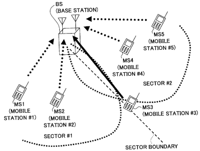
FIG. 1 is an overall view of a mobile
communication system employing CDMA according to an
embodiment of the present invention. The communication
system includes one or more mobile stations MS1 through
MS 5 and a base station BS. Each mobile station
basically belongs to one sector. As an exception,
however, a mobile station located at a sector boundary
may belong to multiple sectors as in the case of the
mobile station MS3. Each mobile station is able to use
one or more of multiple frequency bands. In this
embodiment, it is assumed that the following frequency
bands are available: 20 MHz band, 10 MHz band that is a
part of the 20 MHz band, 5 MHz band that is a part of
the 10 MHz band, 2.5 MHz band that is a part of the 5
MHz band, and 1.25 MHz band that is a part of the 2.5
MHz band. The number of frequency bands and the
bandwidths of frequency bands are not limited to those
mentioned above. In this embodiment, various uplink
channels (indicated by arrow lines from mobile stations
CA 02637648 2008-07-17
-7-
to the base station in FIG. 1) received at the base
station are synchronized to some extent. Although the
synchronization is not at chip level, according to the
present invention, uplink channels of the same type
received within a certain period become orthogonal to
each other.
FIG. 2 is a partial block diagram illustrating
a mobile station. The mobile station shown in FIG. 2
includes a pilot channel generating unit 21, a shifting
unit 22, a first mapping unit 23, a data channel
generating unit 24, a code spreading unit 25, a second
mapping unit 26, a multiplexing unit 27, and a
transmission timing adjusting unit 28.
The pilot channel generating unit 21 generates
a pilot channel comprising a CAZAC code based on code
assignment information. The CAZAC code is described
below.
In FIG. 3, the code length of a CAZAC code A
is L. For descriptive purposes, it is assumed that the
code length corresponds to the duration of L samples.
However, this assumption is not essential to the present
invention. A CAZAC code B shown in the lower part of FIG.
3 is generated by moving A samples (indicated by
hatching) including the sample (the L-th sample) at the
end of the CAZAC code A to the head of the CAZAC code A.
In this case, with regard to A =1 through (L-1), the
CAZAC codes A and B are orthogonal to each other. That
is, a base CAZAC code and a CAZAC code generated by
cyclically shifting the base CAZAC code are orthogonal
to each other. Therefore, theoretically, when one CAZAC
code with a code length L is given, it is possible to
generate a group of L CAZAC codes that are orthogonal to
each other.
CA 02637648 2008-07-17
,
-8-
In this embodiment, CAZAC codes selected from
a group of CAZAC codes having the above described
characteristic are used as pilot channels of mobile
stations. More specifically, in this embodiment, among L
orthogonal codes, L/LA CAZAC codes obtained by
cyclically shifting a base CAZAC code by n x LA (n=1,
2, ..., L/LA) are actually used as pilot signals of
mobile stations. As a result, uplink channels from
mobile stations become orthogonal to each other. Details
of the CAZAC code are described, for example, in the
following documents: D.C. Chu, "Polyphase codes with
good periodic correlation properties", IEEE Trans.
Inform. Theory, vol. IT-18, pp. 531-532, July 1972; 3GPP,
R1-050822, Texas Instruments, "On allocation of uplink
sub-channels in EUTRA SC-FDMA".
The shifting unit 22 shown in FIG. 2
cyclically shifts a pilot channel (CAZAC code) generated
by the pilot channel generating unit 21 and outputs the
shifted pilot channel. The shift amount (n x LA) is set
for each mobile station.
The first mapping unit 23 maps the pilot
channel comprising the CAZAC code to a signal including
multiple frequency components arranged at regular
intervals in a frequency band currently being used by
the mobile station. Specifically, the first mapping unit
23 maps the pilot channel to multiple frequency
components such that a transmission signal of its own
mobile station and transmission signals of other mobile
stations using frequency bands different from that of
the own mobile station become orthogonal to each other
on the frequency axis. This mapping method may be called
distributed FDMA.
FIG. 4 is a drawing illustrating exemplary
CA 02637648 2008-07-17
-9-
mapping of uplink pilot channels. As described above, in
this embodiment, mobile stations can use various
frequency bands. A pilot channel of a mobile station
using the 1.25 MHz band is mapped to two frequency
components on the left. A pilot channel of a mobile
station using the 5 MHz band is mapped to eight
frequency components arranged at regular intervals on
the left. A pilot channel of a mobile station using the
MHz band is mapped to 16 frequency components
10 arranged at regular intervals. As shown in FIG. 4, pilot
channels of the mobile stations using different
frequency bands are mapped so as to become orthogonal to
each other on the frequency axis. Mapping information
indicating how to map pilot channels may be sent from
the base station together with uplink scheduling
information.
Various techniques may be used to map pilot
channels as shown in FIG. 4. One of the techniques
employs a single-carrier method. This technique achieves
mapping in the frequency domain as shown in FIG. 4 by
using fast Fourier transform (FFT) and inverse Fast
Fourier transform (IFFT).
There is another technique that also employs a
single-carrier method and uses variable spreading and
chip repetition factors-CDMA (VSCRF-CDMA).
In this technique, a pilot channel is time-
compressed and repeated, and further, a phase rotation
set for each mobile station is applied to the pilot
channel to convert it into a signal having a comb-like
frequency spectrum as shown in FIG. 4. Still another
technique employs a multicarrier method. This technique
directly achieves mapping as shown in FIG. 4 by
separately specifying subcarriers used for multicarrier
CA 02637648 2008-07-17
-10-
transmission. In terms of reducing the peak-to-average
power ratio of uplink, techniques using single-carrier
methods are preferably used.
The data channel generating unit 24 shown in
FIG. 2 generates a data channel. Although data channels
are normally categorized into control data channels and
user traffic data channels, they are not distinguished
here for brevity.
The code spreading unit 25 multiplies a data
channel by a scramble code and thereby performs code
spreading.
The second mapping unit 26, similarly to the
first mapping unit 23, maps the data channel to be
transmitted to a signal including multiple frequency
components arranged at regular intervals in a frequency
band currently being used by the mobile station. This
mapping may also be performed such that a transmission
signal of the own mobile station and transmission
signals of other mobile stations using frequency bands
different from the frequency band of the own mobile
station become orthogonal to each other on the frequency
axis.
The multiplexing unit 27 multiplexes the
mapped pilot channel and data channel to generate a
transmission signal. The multiplexing may be performed
using one or both of time-division multiplexing and
frequency-division multiplexing. However, code division
multiplexing (CDM) is not used here. This is because
superior autocorrelation characteristics (orthogonality
between delay paths of a pilot channel from each mobile
station and orthogonality between codes obtained by
cyclic shift) of the CAZAC code is lost if the CAZAC
code is multiplied by still another code. Multiplexing
CA 02637648 2008-07-17
-11-
the pilot channel and the data channel by the
multiplexing unit 27 is not essential to the present
invention. For example, the pilot channel may be sent
separately to the base station during a given period.
The transmission timing adjusting unit 28
adjusts the timing of transmitting the transmission
signal according to scheduling information from the base
station so that signals received by the base station
from multiple mobile stations are synchronized with each
other.
In this embodiment, uplink channels (pilot
channels) of mobile stations using different frequency
bands are distinguished by using distributed FDMA as
shown in FIG. 4. In the example shown in FIG. 4, all
pilot channels of the mobile stations using the 1.25 MHz,
5 MHz, and 10 MHz bands are orthogonalized on the
frequency axis by using distributed FDMA.
Meanwhile, uplink pilot channels of mobile
stations using the same frequency band are distinguished
based on the orthogonality of CAZAC codes. FIG. 5 shows
(groups of) CAZAC codes used to distinguish mobile
stations using the same frequency band. As described
above, a base CAZAC code and a CAZAC code generated by
cyclically shifting the base CAZAC code are orthogonal
to each other. In this embodiment, the amount of delay L
is set at a proper value, and a group of codes
generated by cyclically shifting a base CAZAC code by
integral multiples of LA are used for pilot channels.
For example, a code group C
including N CAZAC codes
orthogonal to each other is obtained by cyclically
shifting CAZAC code C#1 by integral multiples of LA. As
shown in FIG. 5, codes in the code group ON are assigned
to users #1, #2, and so forth in the order mentioned.
CA 02637648 2008-07-17
-12-
With this approach, N users can be distinguished. If
there is an N+lth user, another code group Cm including
M orthogonal codes is obtained based on CAZAC code C#2
different from CAZAC code Cl, and the codes in the code
group Cm are assigned to N+lth and later users. Thus, it
is possible to assign CAZAC codes to N+M users and
thereby to distinguish the users. In this manner, CAZAC
codes can be assigned to many users. Meanwhile, there is
no orthogonal relationship between the code group CN and
the code group Cm, and therefore a small amount of
intersymbol interference is caused between them. Still,
because the orthogonality between N codes in the code
group CN is completely maintained and the orthogonality
between M codes in the code group Cm is completely
maintained, the degree of intersymbol interference in
this embodiment is far less than the intersymbol
interference that occurs when codes other than CAZAC
codes are used for pilot channels. Although the same
shift amount Lb, is used for the code groups CN and Cm in
the above descriptions, different shift amounts may be
used for the respective groups. However, using the same
shift amount makes it possible to generate the same
number of codes from each base CAZAC code because the
code length of pilot channels is the same, and therefore
may make it easier to manage codes.
FIG. 6 is a partial block diagram of a base
station according to an embodiment of the present
invention. FIG. 6 shows components necessary to perform
a process for one mobile station. In an actual
configuration, sets of the components are provided for a
number of concurrent mobile stations. The base station
shown in FIG. 6 includes a separating unit 60, a
demodulation unit 61, a path searcher 62 (including
CA 02637648 2008-07-17
-13-
correlation detecting unit 63 and a reception timing
detecting unit 64), a channel estimation unit 65, and a
pilot replica generating unit 66 (including a pilot
channel generating unit 67, a shifting unit 68, and a
= 5 mapping unit 69).
The separating unit 60 separates a pilot
channel and a data channel in a received signal sent
from the mobile station.
The demodulation unit 61 demodulates the data
channel based on the result of channel estimation.
The path searcher 62 performs a path search
using the pilot channel.
The correlation detecting unit 63 calculates
the correlation between a pilot channel replica and the
received pilot channel and outputs the correlation
calculation result.
The reception timing detecting unit 64 detects
a reception timing by analyzing the timing and size of a
peak indicated by the correlation calculation result.
The channel estimation unit 65 performs
channel estimation based on the result of the path
search.
The pilot replica generating unit 66 generates
a pilot channel replica. The pilot channel generating
unit 67, the shifting unit 68, and the mapping unit 69
of the pilot channel replica generating unit 66 have
functions similar to those of the corresponding
components 21, 22, and 23 of the mobile station.
The pilot channel generating unit 67 generates
a pilot channel comprising a CAZAC code based on code
assignment information.
The shifting unit 68 cyclically shifts the
CAZAC code by a shift amount set for the corresponding
CA 02637648 2008-07-17
-14-
mobile station a signal of which is to be processed.
The mapping unit 69 maps the pilot channel
comprising the CAZAC code to a signal including multiple
frequency components arranged at regular intervals in a
frequency band currently being used by the mobile
station.
In this embodiment, as described above, uplink
channels (pilot channels) of mobile stations using
different frequency bands are distinguished by the base
station by using distributed FDMA as shown in FIG. 4.
Meanwhile, uplink pilot channels of mobile stations
using the same frequency band are distinguished by the
based station based on the orthogonality of CAZAC codes.
A base CAZAC code and a CAZAC code generated
by cyclically shifting the base CAZAC code are
orthogonal to each other. This indicates that a group of
delay paths of a pilot channel comprising a CAZAC code
are also orthogonal to each other. That is, a delay path
delayed by 7 from the first path of a pilot channel
corresponds to a pilot channel generated by cyclically
shifting the pilot channel of the first path by r. Thus,
using CAZAC codes generated by cyclically shifting a
base CAZAC code as in this embodiment makes it possible
to achieve orthogonality between mobile stations and
also to maintain the orthogonality between delay paths
of a pilot channel from each mobile station. This in
turn makes it possible to reduce intersymbol
interference observed at the base station to a very low
level.
<SECOND EMBODIMENT>
According to a second embodiment of the
present invention, although CAZAC codes are used for
CA 02637648 2008-07-17
-15-
pilot channels of multiple mobile stations using the
same frequency band, the CAZAC codes are not generated
by cyclically shifting a base CAZAC code, but are
generated independently for the respective mobile
stations.
FIG. 7 shows CAZAC codes used in this
embodiment to distinguish mobile stations using the same
frequency band. In FIG. 7, CAZAC code #1 and CAZAC code
#2 are not generated by cyclic shift and are not
orthogonal to each other. In this case, the intersymbol
interference between mobile stations may become as large
as the intersymbol interference that occurs when codes
other than CAZAC codes, such as random sequences, are
used. However, since CAZAC codes are used for pilot
channels, the orthogonality between delay paths of each
pilot channel is maintained as in the first embodiment.
Therefore, compared with a case where codes other than
CAZAC codes are used, this embodiment makes it possible
to dramatically reduce the interference between delay
paths and makes it possible to reduce the total
intersymbol interference observed at the base station at
least by the reduction of the interference between delay
paths. Also, the second embodiment can be applied to a
conventional system more easily than the first
embodiment because there is no need to control the shift
amount of CAZAC codes.
<THIRD EMBODIMENT>
In the first embodiment, mobile stations using
the same frequency band are distinguished based solely
on CDMA with CAZAC codes. In a third embodiment, both
distributed FDMA and CDMA with CAZAC codes are used. In
this embodiment, distributed FDMA is first used to
CA 02637648 2008-07-17
-16-
distinguish mobile stations. When there are a large
number of mobile stations and it is not possible to
distinguish mobile stations only by distributed FDMA,
the mobile stations are distinguished by CDMA with CAZAC
codes (either by the method of the first embodiment or
the method of the second embodiment). With distributed
FDMA, signals mapped to frequency components become
completely orthogonal to each other. Therefore,
distributed FDMA is preferable in terms of reducing
interference. The interval between frequency components
(in the comb-like frequency spectrum) used in
distributed FDMA can be adjusted to some extent. For
example, in FIG. 4, eight frequency components are
arranged at regular intervals in the 5 MHz band. The
interval may be doubled such that four frequency
components are arranged in the 5 MHz band. In this case,
as shown in FIG. 8, it is possible to map a pilot
channel of another mobile station using the 5 MHz band
to the remaining four frequency components. FIG. 8 shows
mapping of pilot channels where two users are
multiplexed in the 5 MHz band by doubling the interval
between comb-like frequency components. Thus, by
adjusting the interval between frequency components, it
is possible to increase the number of pilot channels of
mobile stations using the same frequency band that can
be distinguished using distributed FDMA. However, the
number of pilot channels distinguishable by this
approach is limited. Therefore, if the number of mobile
stations is larger than the limit, the CDMA schemes
described in the first and second embodiments are used
to distinguish the pilot channels of the mobile stations.
The present invention is not limited to the
specifically disclosed embodiments, and variations and
ak 02637648 2014-01-29
-17-
modifications may be made without departing from the
scope of the present invention. Although the present
invention is described above in different embodiments,
the distinctions between the embodiments are not
essential for the present invention, and the embodiments
may be used individually or in combination.