Note: Descriptions are shown in the official language in which they were submitted.
CA 02637656 2013-10-10
1
GLAUCOMA TREATMENT DEVICE
10
BACKGROUND
This disclosure relates generally to methods and devices for use In treating
glaucoma. The mechanisms that cause glaucoma are not completely known. It is
known that glaucoma results in abnormally high pressure In the eye, which
leads to
optic nerve damage. Over time, the Increased pressure can cause damage to the
optic nerve, which can lead to blindness. Treatment strategies have focused on
keeping the Intraocular pressure down in order to preserve as much vision as
possible over the remainder of the patient's life.
Past treatment has included the use of drugs that lower Intraocular pressure
through various mechanisms. The glaucoma drug market Is an approximate two
CA 02637656 2013-10-10
2
billion dollar market. The large market is mostly due to the fact that there
are not
any effective surgical alternatives that are long lasting and complication-
free.
Unfortunately, drug treatments need much improvement, as they can cause
adverse
side effects and often fall to adequately control intraocular pressure.
Moreover,
patients are often lackadaisical in following proper drug treatment regimens,
resulting in a lack of compliance and further symptom progression.
With respect to surgical procedures, one way to treat glaucoma is to implant
a drainage device, or shunt, in the eye. The drainage device functions to
drain
aqueous humour from the anterior chamber and thereby reduce the intraocular
pressure. The drainage device is typically implanted using an invasive
surgical
procedure. Pursuant to one such procedure, a flap Is surgically formed In the
sclera. The flap is folded back to form a small cavity and a shunt is Inserted
into the
eye through the flap. Such a procedure can be quite traumatic as the implant
are
large and can result in various adverse events such as infections and
scarring,
leading to the need to re-operate.
The following references describe various devices and procedures for
treating glaucoma: United States Patent 6,827,700 to Lynch, 6,666,841 to
Berghelm, 6,508,779 to Suson, 6,544,208 to Ethier, 5,601,094 to Reiss,
6,102,045
to Nordquist, United States Patent Application 2002/0156413 to Williams,
2002/0143284 to Tu, 2003/0236483 to Ran, 2002/0193725 to Odrich,
2002/0165478 to Ghent), 2002/0133168 to Smedley, 2005/0107734, 2004/0260228
to Lynch, 2004/0102729 to Haffner, 2004/0015140 to Shields, 2004/0254521 to
Simon, and 2004/0225250 to Yablonski.
Current devices and procedures for treating glaucoma have disadvantages
and only moderate success rates. The procedures are very traumatic to the eye
and also require highly accurate surgical skills, such as to properly place
the
drainage device In a proper location. In addition, the devices that drain,
fluid from
the anterior chamber to a subconjunctival bleb beneath a scieral flap are
prone to
CA 02637656 2008-07-17
WO 2007/087061 PCT/US2006/049234
3 =
infection, and can occlude and cease working. This can require re-operation to
remove the device and place another one, or can result in further surgeries.
In view
of the foregoing, there is a need for improved devices and methods for the
treatment
of glaucoma.
SUMMARY
Disclosed are devices and methods for treatment of eye disease such as
glaucoma. A shunt is placed in the eye wherein the shunt provides a fluid
pathway
for the flow or drainage of aqueous humour from the anterior chamber to the
suprachoroidal space. The shunt is implanted in the eye using a delivery
system
that uses a minimally invasive procedure, as described below. By guiding fluid
directly into the supraciliary or suprachoroidal space rather than to the
surface of the
eye, complications commonly encountered with conventional glaucoma surgery
should be avoided. Shunting aqueous fluid flow directly into the supraciliary
or
suprachoroidal space should minimize scarring since the angle region is
populated
with a single line of non-proliferating trabecular cells. Shunting aqueous
flow directly
into the supraciliary or suprachoroidal space should minimize hypotony and
also
potentially eliminate complications such as endophthalmitis and leaks since an
external filtering bleb is not the goal of surgery. The device described
herein is
designed to enhance aqueous flow through the normal outflow system of the eye
with minimal to no complications. Any of the procedures and device described
herein can be performed in conjunction with other therapeutic procedures, such
as
laser iridotomy, laser iridoplasty, and goniosynechialysis (a cyclodialysis
procedure).
In one aspect, there is disclosed a glaucoma treatment device comprising an
elongate member having a flow pathway, at least one inflow port communicating
with the flow pathway, and an outflow port communicating with the flow
pathway.
The inflow port and outflow port are positioned such that the flow pathway
provides
a fluid pathway between an anterior chamber and a suprachoroidal space when
the
elongate member is implanted in the eye.
CA 02637656 2008-07-17
WO 2007/087061 PCT/US2006/049234
4
Among the methods provided herein, is a method of implanting an ocular
device into the eye, comprising forming an incision in the cornea of the eye;
inserting a shunt through the incision into the anterior chamber of the eye
wherein
the shunt includes a fluid passageway; passing the shunt along a pathway from
the
anterior chamber through the scleral spur of the eye into the suprachoroidal
space;
and positioning the shunt in a first position such that a first portion of the
fluid
passageway communicates with the anterior chamber and a second portion of the
fluid passageway communicates with the suprachoroidal space to provide a fluid
passageway between the suprachoroidal space and the anterior chamber.
In other embodiments, provided herein is a method of implanting an ocular
device into the eye, comprising forming an incision in the cornea of the eye;
insei-ting a shunt through the incision into the anterior chamber of the eye
wherein at
least a portion of the shunt can be opened to permit fluid flow along the
shunt;
passing the shunt along a pathway from the anterior chamber through the
sclera!
spur of the eye into the suprachoroidal space; positioning the shunt in a
first position
such that a first portion of the shunt communicates with the anterior chamber
and a
second portion of the shunt communicates with the suprachoroidal space; and
opening the shunt to permit fluid flow so that the shunt provides a fluid
passageway
between the suprachoroidal space and the anterior chamber.
In other embodiments, provided herein is a method of implanting an ocular
device into the eye, comprising forming an incision in the cornea of the eye;
mounting a shunt on a delivery device wherein at least a portion of the shunt
or the
delivery device has a curvature that matches a curvature of the eye; inserting
the
shunt through the incision into the anterior chamber of the eye wherein the
shunt
includes a fluid passageway; aiming the shunt relative to the suprachoroidal
space
such that the curvature of the shunt or the delivery device aligns with the
curvature
of the eye; and inserting at least a portion of the shunt into the
suprachoroidal space
to provide a fluid passageway between the suprachoroidal space and the
anterior
chamber.
CA 02637656 2008-07-17
WO 2007/087061 PCT/US2006/049234
In still further embodiments, provided herein is a method of implanting an
ocular device into the eye, comprising forming an incision in the cornea of
the eye;
inserting a shunt through the incision into the anterior chamber of the eye
wherein
the shunt includes a fluid passageway; passing the shunt along a pathway from
the
5 anterior chamber through the scleral spur of the eye into the
suprachoroidal space;
and positioning the shunt in a first position such that a first portion of the
fluid
passageway communicates with the anterior chamber and a second portion of the
fluid passageway communicates with the suprachoroidal space to provide a fluid
passageway between the uprachoroidal space and the anterior chamber wherein
the shunt is pre-shaped to position the first portion away from the iris.
In further embodiments, provided herein is a method of implanting an ocular
device into the eye, comprising forming an incision in the sclera of the eye;
inserting
a shunt through the incision into the suprachoroidal space of the eye wherein
the
shunt includes a fluid passageway; passing the shunt along a pathway from the
suprachoroidal space through the scleral spur of the eye into the anterior
chamber;
and positioning the shunt in a first position such that a first portion of the
fluid
passageway communicates with the anterior chamber and a second portion of the
fluid passageway communicates with the suprachoroidal space to provide a fluid
passageway between the suprachoroidal space and the anterior chamber.
Also provided herein, is a glaucoma treatment device, comprising an
elongate member having a flow pathway, at least one inflow port communicating
with the flow pathway, and an outflow port communicating with the flow
pathway,
wherein the elongate member is adapted to be positioned in the eye such that
the
inflow port communicates with the anterior chamber, the outflow port
communicates
with the suprachoroidal space, and at least a portion of the elongate member
passes through the scleral spur to provide a fluid pathway between the
anterior
chamber and the suprachoroidal space when the elongate member is implanted in
the eye.
CA 02637656 2008-07-17
WO 2007/087061 PCT/US2006/049234
6
In other embodiments, provided herein is a glaucoma treatment device,
comprising an elongate member having a flow pathway, at least one inflow port
communicating with the flow pathway, and an outflow port communicating with
the
flow pathway, wherein the elongate member is adapted to be positioned in the
eye
such that the inflow port communicates with the anterior chamber and the
outflow
port communicates with the suprachoroidal space, wherein at least a portion of
the
=
elongate member includes an enlarged bulbous region adapted to form a space
within the suprachoroidal space for accumulation of fluid within the
suprachoroidal
space.
In another embodiment, provided herein is a glaucoma treatment device,
comprising an elongate member having a flow pathway, at least one inflow port
communicating with the flow pathway, and an outflow port communicating with
the
flow pathway, wherein the elongate member is adapted to be positioned in the
eye
such that the inflow port communicates with the anterior chamber and the
outflow
port communicates with the suprachoroidal space, the elongate member having a
first region and a second region, wherein the second region is adapted to
transition
from a first shape to a second shape while the first regions remains
unchanged.
In another embodiment, provided herein is a glaucoma treatment device,
comprising a curved member sized to fit within an angle between the cornea and
the
iris of an eye; at least two legs extending outwardly from the curved member
and
shaped to extend into the suprachoroidal space, wherein at least one of the
legs
provides a fluid flow pathway into the suprachoroidal space.
In still further embodiments, provided herein is a glaucoma treatment system,
comprising an elongate member having a flow pathway, at least one inflow port
communicating with the flow pathway, and an outflow port communicating with
the
flow pathway, wherein the elongate member is adapted to be positioned in the
eye
such that the inflow port communicates with the anterior chamber and the
outflow
port communicates with the suprachoroidal space, wherein at least a portion of
the
elongate member includes an enlarged bulbous region adapted to form a space
CA 02637656 2008-07-17
WO 2007/087061 PCT/US2006/049234
7
within the suprachoroidal space for accumulation of fluid within the
suprachoroidal
space; and a delivery device having an elongate applier that removably
attaches to
the elongate member, the delivery device including an actuator that removes
the
elongate member from the applier.
Other features and advantages should be apparent from the following
description of various embodiments, Which illustrate, by way of example, the
principles of the invention.
BRIEF DESCRIPTION OF THE DRAWINGS
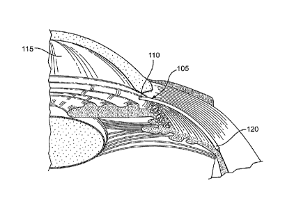
Figure 1 is a cross-sectional, perspective view of a portion of the eye
showing
the anterior and posterior chambers of the eye.
Figure 2 is a cross-sectional view of a human eye.
Figure 3A shows a first embodiment of any eye shunt.
Figure 3B shows a shunt formed of an elongate wick member through which
fluid can flow.
Figure 3C shows a shunt that combines a tube and a wicked member.
Figure 4 shows the shunt including one or more retention structures.
Figure 5 shows an exemplary embodiment of a delivery system that can be
used to deliver the shunt into the eye.
Figure 6A shows another embodiment of a delivery system.
Figure 6B shows another embodiment of a delivery system.
Figures 6C and 6D show the delivery system of Figure 6B during actuation.
Figures 6E-6G show a distal region of the delivery system during various
stages of actuation.
Figure 6H shows an enlarged view of an exemplary distal region of an applier
of the delivery system.
Figure 7 shows an enlarged view of an end region of the shunt.
Figure 8 shows another embodiment of the shunt wherein a plurality of holes
are located on the side walls of the shunt.
CA 02637656 2008-07-17
WO 2007/087061 PCT/US2006/049234
8
Figure 9A shows another embodiment of the shunt that includes an elongate
portion of fixed size and one or more expansion members.
Figure 98 shows an embodiment of the expansion members that are formed
of splayed tines.
Figure 10 shows another embodiment of the shunt that includes a retaining
member located on the proximal end of the shunt.
Figure 11 shows an embodiment of the shunt that includes one or more slots. =
Figure 12 shows an embodiment of the shunt that includes a distal coil
member.
Figure 13 shows a distal region of an embodiment of the shunt that includes
a distal coil member and a sharpened distal end.
Figure 14 shows a cross-sectional view of the eye and a viewing lens.
Figure 15A shows the delivery system positioned for penetration into the eye.
Figure 15B shows an embodiment wherein the delivery system is connected
to an energy source.
Figure 16 shows an enlarged view of the anterior region of the eye with a
portion of the delivery system positioned in the anterior chamber.
Figure 17 shows the distal tip of the applier positioned within the
suprachoroidal space.
Figure 18 shows a shunt having a skirt.
Figure 19 shows a shunt that is equipped with a pronged skirt.
Figure 20 shows the skirted shunt positioned in the eye.
Figure 21 shows a shunt implanted in the eye so as to provide a fluid
pathway between the anterior chamber and the suprachoroidal space.
Figures 22 and 23 shows shunts that include external fluid flow features.
Figure 24, 25A, and 25B shows a shunt that includes an elongate outer
member mounted over a plug member.
Figure 26 shows an embodiment of the shunt formed of a sponge-like flow
member.
CA 02637656 2008-07-17
WO 2007/087061 PCT/US2006/049234
9
Figure 27 shows a shunt as in Figure 26 having an internal lumen.
Figure 28 shows an embodiment of the shunt that includes a pair of anchor
members located on opposite ends of the shunt.
Figure 29 shows an end region of the shunt that includes slices.
Figure 30 shows an embodiment of the shunt with outer sleeves.
Figure 31 shows another embodiment of the shunt with sleeves.
Figure 32 shows another embodiment of the shunt, which has a coiled
structure. '
Figures 33A and 33B and 34 show embodiments of the shunt that include a
grasping loop.
Figure 35 shows an embodiment of an elongate device with a snare that can
be positioned inside a shunt.
Figure 36 shows an embodiment of a spatula-shaped end region of a shunt.
Figure 37 shows a shunt, having an atraumatic tip.
Figure 38 shows an embodiment wherein the shunt that includes a.resilient
region.
Figures 39, 40A, and 40B show alternate embodiments of the shunt.
Figure 41 shows an embodiment of the shunt with holes that communicate
with an internal lumen.
Figures 42A, 42B, and 43 show embodiments of the shunt that include Valved
- regions.
Figures 44 and 45 show embodiments of the shunt that include one or more
bulbous elements.
Figures 46 and 47 show embodiments of the bulbous element shunt
positioned in the suprachoroidal space.
Figure 48 shows an embodiment of the shunt that includes a bullet-shaped
tip member.
Figure 49 shows an embodiment of a shunt that mounts over a mandrel.
CA 02637656 2008-07-17
WO 2007/087061 PCT/US2006/049234
Figures 50 and 51A show embodiments of shunts that change shape after
removal from a mandrel.
Figure 51B shows another embodiment of a shunt.
Figure 51C shows another embodiment of a shunt.
5 Figure 52 shows a shunt with a curved proximal region positioned in the
eye.
Figure 53 shows a schematic, front view of the upper region of a patient's
face including the two eyes.
Figures 54A and 54B show perspective and plan views of an exemplary
delivery pathway of the applier and shunt during implantation of the shunt
into the
10 eye.
Figures 55A-55D show plan and perspective views of a delivery system being
inserted into the eye.
Figure 56 shows a plan view of an exemplary delivery pathway.
Figure 57 shows a perspective view of an alternate delivery pathway into the
eye.
Figures 58A-58D show yet another delivery pathway into the eye.
Figure 59 shows a shunt having an extension sized and positioned such that
a proximal end is positioned over a crest of the iris.
Figure 60 shows a shunt with a curved extension positioned in the eye.
Figure 61 shows another embodiment wherein the shunt extends through the
iris such that the proximal end and the internal lumen of the shunt
communicate with
the posterior chamber.
Figures 62 and 63 show a trans-scleral delivery approach for the shunt.
DETAILED DESCRIPTION
Figure 1 is a cross-sectional, perspective view of a portion of the eye
showing
the anterior and posterior chambers of the eye. A shunt 105 is positioned
inside the
eye such that a proximal end 110 is located in the anterior chamber 115 and a
distal
end 120 is located in the suprachoroidal space (sometimes referred to as the
CA 02637656 2008-07-17
WO 2007/087061 PC
T/US2006/049234
11
perichoroidal space). The shunt 105 is illustrated in Figure 1 as an elongate
element having one or more internal lumens through which aqueous humour can
flow from the anterior chamber 115 into the suprachoroidal space. Embodiments
of
the shunt 105 with various structural configurations are described in detail
below.
Exemplary Eye Anatomy
Figure 2 is a cross-sectional view of a human eye. The eye is generally
spherical and is covered on the outside by the sclera S. The retina R lines
the
inside posterior half of the eye. The retina registers the light and sends
signals to
the brain via the optic nerve. The bulk of the eye is filled and supported by
the
vitreous body, a clear, jelly-like substance.
The elastic lens L is located near the front of the eye. The lens L provides
adjustment of focus and is suspended within a capsular bag from the ciliary
body
CB, which contains the Muscles that change the focal length of the lens. A
volume
in front of the lens L is divided into two by the iris I, which controls the
aperture of
the lens and the amount of light striking the retina. The pupil is a hole in
the center
of the iris I through which light passes. The volume between the iris I and
the lens L
is the posterior chamber PC. The volume between the iris I and the cornea is
the
anterior chamber AC. Both chambers are filled with a clear liquid known as
aqueous humour.
The ciliary body CB continuously forms aqueous humour in the posterior
chamber PC by secretion from the blood vessels. The aqueous humour flow
around the lens L and iris I into the anterior chamber and exits the eye
through the
trabecular meshwork, a sieve-like structure situated at the corner of the iris
I and the
wall of the eye (the corner is known as the iridocomeal angle). Some of the
aqueous humour filters through the trabecular meshwork into Schlemm's canal, a
small channel that drains into the ocular veins. A smaller portion rejoins the
venous
circulation after passing through the ciliary body and eventually through the
sclera
(the uveoscleral route).
CA 02637656 2008-07-17
WO 2007/087061 PCT/US2006/049234
12
Glaucoma is a disease wherein the aqueous humor builds up within the eye.
In a healthy eye, the ciliary processes secrete aqueous humor, which then
passes
through the angle between the cornea and the iris. Glaucoma appears to be the
result of clogging in the trabecular meshwork. The clogging can be caused by
the
exfoliation of cells or other debris. When the aqueous humor does not drain
properly from the clogged meshwork, it builds up and causes increased pressure
in
the eye, particularly on the blood vessels that lead to the optic nerve. The
high
pressure on the blood vessels can result in death of retinal ganglion cells
and
eventual blindness.
Closed angle (acute) glaucoma can occur in people who were born with a
narrow angle between the iris and the cornea (the anterior chamber angle).
This is
more common in people who are farsighted (they see objects in the distance
better
than those which are close up). The iris can slip forward and suddenly close
off the
exit of aqueous humor, and a sudden increase in pressure within the eye
follows.
Open angle (chronic) glaucoma is by far the most common type of glaucoma.
In open angle glaucoma, the iris does not block the drainage angle as it does
in
acute glaucoma. Instead, the fluid outlet channels within the wall of the eye
gradually narrow with time. The disease usually affects both eyes, and over a
period
of years the consistently elevated pressure slowly damages the optic nerve.
Shunt and Delivery System
Figure 3A shows a first embodiment of the shunt 105. As mentioned, the
shunt 105 is an elongate member having a proximal end 110, a distal end 120,
and
a structure that permits fluid (such as aqueous humour) to flow along the
length of
the shunt such as through the shunt or around the shunt. In the embodiment of
Figure 3A, the elongate member includes at least one internal lumen 305 having
at
least one opening for ingress of fluid and at least one opening for egress of
fluid. In
the embodiment of Figure 3A, the shunt includes a single opening in the
proximal
end 110 and a single opening in the distal end 120 that both communicate with
the
CA 02637656 2008-07-17
WO 2007/087061 PCT/US2006/049234
13
=
internal lumen 305. However, the shunt 105 can include various arrangements of
openings that communicate with the lumen(s), as described below.
The internal lumen 305 serves as a passageway for the flow of aqueous
humour through the shunt 105 directly from the anterior chamber to the
suprachoroidal space. In addition, the internal lumen 305 can be used to mount
the
shunt 105 onto a delivery system, as described below. The internal lumen 305
can
also be used as a pathway for flowing irrigation fluid into the eye generally
for
flushing or to maintain pressure in the anterior chamber, or using the fluid
to
hydraulically create a dissection plane into or within the suprachoroidal
space. In
the embodiment of Figure 3A, the shunt 105 has a substantially uniform
diameter
along its entire length, although the diameter of the shunt can vary along its
length,
as described below. Moreover, although the shunt 105 is shown as having a
circular
cross-sectional shape, the shunt can have various cross-sectional shapes (such
as
an oval or rectangular shape) and can vary in cross-sectional shape moving
along
its length. The cross-sectional shape can be selected to facilitate easy
insertion into
the eye.
The shunt 105 can include one or more features that aid in properly
positioning the shunt 105 in the eye. For example, the shunt can have one or
more
visual, tomographic, echogenic, or radiopaque markers 112 that can be used to
aid
in placement using any of the devices referenced above tuned to its applicable
marker system. In using the markers to properly place the implant, the shunt
is
inserted in the suprachoroidal space, until the marker is aligned with a
relevant
anatomic structure, for example, visually identifying a marker on the anterior
chamber portion of the shunt that aligns with the trabecular meshwork, or
sclera!
spur, such that an appropriate length of the shunt remains in the anterior
chamber.
Under ultrasound, an echogenic marker can signal the placement of the device
within the suprachoroidal space. Any marker can be placed anywhere on the
device
to provide sensory feedback to the user on real-time placement, confirmation
of
CA 02637656 2008-07-17
WO 2007/087061 PCT/US2006/049234
14
placement or during patient follow up. Other structural features are described
below.
The shunt 105 can also include structural features that aid in anchoring or
retaining the implanted shunt 105 in the eye. For example, as shown in Figure
4,
the shunt 105 can include one or more retaining or retention structures 410,
such as
protrusions, wings, tines, or prongs, that lodge into anatomy to retain the
shunt in
place. The retention structures 410 can be deformable or stiff. The retention
structures 410 can be made of various biocompatible. materials. For example,
the
retention structures 410 can be made from thin 0.001" thick polyimide, which
is
flexible, thin 0.003" silicone elastomer which is also flexible, or stainless
steel or
Nitinol. Alternatively, the retention structures 410 could be rings of
polyimide. It
should be appreciated that other materials can be used to make the retention
structures 410. The shape of retention structures 410 can vary. For example,
Figure 4 shows the retention structures 410 as barb-shaped with pointed edges
of
the barbs pointing in opposite directions. In other embodiment, the retention
structures 410 can be rectangular, triangular, round, combinations thereof, or
other
shapes. Additional embodiments of retention structures 410 are described
below.
Other anchoring or retaining features can be employed with the shunt 105.
For example, one or more hairs, such as human hairs, or synthetic hairs made
from
polymers, elastomers or metals can be attached to the shunt. The hairs cancan
be
glued or thermally bonded to the shunt. The hairs, if they are polyimide, can
be
attached to the shunt by dipping and polymerized by heat and pressure if the
dipping material is polyimide. The hairs can be crimped to the shunt by rings.
Alternatively, the shunt can have through-hole features that the hairs can be
threaded through and tied or knotted. The hairs can be overmolded onto the
shunt
body. The hairs are positioned relative to the shunt such that at least a
portion of
the hair extends outwardly from the shunt for anchoring within or against the
tissue
Of the eye. Various anchoring and retaining features are described herein and
it
=
CA 02637656 2008-07-17
WO 2007/087061 PCT/US2006/049234
should be appreciated that the features can be implemented in any of the
'shunt
embodiments described herein.
The retaining features, such as wings or collars, can be manufactured by
various methods. In one embodiment, the retaining features can be inherent in
the
5 raw material from which the shunt is constructed. The shunt can be
machined or
laser ablated from a unitary rod or block of stock of material with the
material
subtracted or removed, leaving the retaining features behind.
Alternatively, the retaining features can be manufactured as separate parts
and assembled onto the shunt. They can be joined to the shunt by a friction
fit or
10 attached with biocompatible adhesives. They can fit into grooves, holes
or detents in
the body of the shunt to lock them together. If the retaining features are
constructed
from hairs or sutures, they can be threaded or tied onto the shunt.
Alternatively, the
retaining features can be overmolded onto the shunt via an injection molding
process. Alternatively, the entire shunt and retention features can be
injection
15 molded in one step. Alternatively, the retaining features can be formed
into the
shunt with a post-processing step such as flaring or thermoforming parts of
the
shunt.
The shunt 105 can be made of various materials, including, for example,
polyimide, Nitinol, platinum, stainless steel, molybdenum, or any other
suitable
polymer, metal, metal alloy, or ceramic biocompatible material or combinations
thereof. Other materials of manufacture or materials with which the shunt can
be
coated or manufactured entirely include Silicone, PTFE, ePTFE, differential
fluoropolymer, FEP, FEP laminated into nodes of ePTFE, silver coatings (such
as
via a CVD process), gold, prolene/polyolefins, polypropylene, poly(methyl
methacrylate) (PMMA), acrylic, PolyEthylene Terephthalate (PET), Polyethylene
(PE), PLLA, and panjlene. The shunt 105 can be reinforced with polymer,
Nitinol, or
stainless steel braid or coiling or can be a co-extruded or laminated tube
with one or
more materials that provide acceptable flexibility and hoop strength for
adequate
lumen support and drainage through the lumen. The shunt can alternately be
CA 02637656 2008-07-17
WO 2007/087061 PCT/US2006/049234
16
manufactured of nylon (polyamide), PEEK, polysulfone, polyamideimides (PAI),
polyether block amides (Pebax), polyurethanes, thermoplastic elastomers
(Kraton,
etc), and liquid crystal polymers.
Any of the embodiments of the shunt 105 described herein can be coated on
its inner or outer surface with one or more drugs or other materials, wherein
the drug
or material maintains the patency of the lumen or encourages in-growth of
tissue to
assist with retention of the shunt within the eye or to prevent leakage around
the
shunt. The drug can also be used for disease treatment. The shunt can also be
coated on its inner or outer surface with a therapeutic agent, such as a
steroid, an
antibiotic, an anti-inflammatory agent, an anticoagulant, an antiglaucomatous
agent,
an anti proliferative, or any combination thereof. The drug or therapeutic
agent can
be applied in a number of ways as is known in the art. Also the drug can be
embedded in another polymer (nonabsorbable or bioabsorbable) that is coated on
the shunt.
The shunt can also be coated or layered with a material that expands
outward once the shunt has been placed in the eye. The expanded material fills
any
voids that are positioned around the shunt. Such materials include, for
example,
hydrogels, foams, lyophilized collagen, or any material that gels, swells, or
otherwise
expands upon contact with body fluids.
The shunt can also be covered or coated with a material (such as polyester,
ePTFE(also known as GORETEX0), PTFE that provides a surface to promote
healing of the shunt into the surrounding tissue. In order to maintain a low
profile,
well-known sputtering techniques can be employed to coat the shunt. Such a low
profile coating would accomplish a possible goal of preventing migration while
still
allowing easy removal if desired.
In another embodiment shown in Figure 3B that can be useful in some
glaucoma cases depending on how much flow is desired, the shunt 105 is formed
of
an elongate wick member through which fluid can flow. The wick member can be
formed of a single strand of material or can be formed of a plurality of
strands that
CA 02637656 2008-07-17
WO 2007/087061 PCT/US2006/049234
17
are interconnected, such as in a twisted, braided, or woven fashion, and
through or
along which fluid can flow. The wick member(s) do not necessarily include
internal
lumens, as flow through the wick member can occur via capillary action. In the
case of a solid polymer wick, certain surface detents can provide flow lumens
between the central body member and the tissue of the suprachoroidal space.
The features of the shunts shown in Figure 3A and 3B can be combined as
shown in Figure 3C. Thus, the shunt 105 can include one or more wick members
315 in fluid communication with an internal lumen 305 (or external lumen) of
an
elongate member. The flow of aqueous humour occurs both through the internal
lumen 305 and through or along the wick member 315.
In an exemplary embodiment, the shunt has a length in the range of 0.1" to
0.75" and an inner diameter for a flow path in the range of 0.002" to 0.015".
In an
embodiment, the inner diameter is 0.012", 0.010", or 0.008". A wicking shunt
can
have a diameter in the range of 0.002" to 0.025". In the event that multiple
shunts
are used, and for example each shunt is 0.1", the fully implanted device can
create
a length of 0.2" to 1.0", although the length can be outside this range. An
embodiment of the shunt is 0.250" long, 0.012" in inner diameter, and 0.015"
in
outer diameter. One embodiment of the shunt is 0.300" long.
The shunt 105 has a column strength sufficient to permit the shunt 105 to be
inserted into suprachoroidal space such that the distal tip of the shunt 105
tunnels
through the eye tissue (such as the ciliary body) without structural collapse
or
structural degradation of the shunt 105. In addition, the surface of the inner
lumen
305 is sufficiently smooth relative to the delivery device (described in
detail below) to
permit the shunt 105 to slide off of the delivery device during the delivery
process.
In an embodiment, the column strength is sufficient to permit the shunt to
tunnel
through the eye tissue into the suprachoroidal space without any structural
support
from an additional structure such as a delivery device.
The shunt 105 can be configured to transition between a first state of reduced
size and a second state of expanded size. For example, the shunt 105 can be in
a
CA 02637656 2008-07-17
WO 2007/087061 PCT/US2006/049234
18
first state wherein the shunt 105 has a reduced radial size and/or overall
length in
order to facilitate fitting the shunt through a small portal during delivery.
The shunt
can then transition to a second state of increased radial size and/or overall
length.
The shunt can also change cross sectional shape along the length.
The transition between the first and second states can be implemented in
various manners. For example, the shunt can be manufactured of a material such
as Nitinol that deforms in response to temperature variations or a release of
a
constraining element. Thus, the shunt can be self-expanding or self-
restricting at
various locations along the length. In another embodiment or in combination
with a
self-expanding shunt, the shunt can be expanded manually, such as through use
of
an expansion balloon or by passing the shunt along a pre-shaped device, such
as a
reverse-tapered delivery trocar that increases in diameter. In addition, the
shunt can
be positioned inside a sheath during delivery wherein the sheath maintains the
shunt in the first state of reduced size. Upon delivery, the sheath can be
removed to
permit the shunt to expand in size.
Figure 5 shows an exemplary delivery system 510 that can be used to deliver
the shunt 105 into the eye pursuant to methods described in detail below. The
delivery system 510 includes a handle component 515 that controls a shunt
placement mechanism, and a delivery component 520 that removably couples to
the
shunt 105 for delivery of the shunt 105 into the eye. The delivery component
520
includes an elongate applier 525. In one embodiment, the applier 525 has a
sharpened distal tip. The applier 525 is sized to fit through the lumen in the
shunt
105 such that the shunt 105 can be mounted on the applier 525. The applier 525
can have a cross-sectional shape that complements the cross-sectional shape of
the internal lumen of the shunt 105 to facilitate mounting of the shunt onto
the
applier 525. It should be appreciated the applier 525 does not have to employ
a
sharpened distal tip. The applier 525 can have an atraumatic or blunt distal
tip such
that it serves as a component for coupling to the shunt, or performing blunt
dissection, rather than as a cutting component.
CA 02637656 2008-07-17
WO 2007/087061 PCT/US2006/049234
19
The delivery component 520 also includes a shunt deployment or advancing
structure 530 positioned on a proximal end of the applier 525. The advancing
structure 530 can be an elongated tube that is positioned over the applier
525. The
delivery system 510 can be actuated to achieve relative, sliding movement
between
the advancing structure 530 and the applier 525. For example, the advancing
structure 520 can be moved in the distal direction (as represented by the
arrow
532), while the applier 525 remains stationary to push or otherwise advance
the
shunt 105 along the applier 525 for delivery of the shunt 105 into the eye. In
an
alternate embodiment, the applier 525 withdraws distally into the advancing
structure 530 to remove the shunt 105 from the applier 525, as described below
with
reference to Figure 6B. In yet another embodiment, both the advancing
structure
530 and the applier 525 move relative to one another to remove the shunt 105.
In an embodiment, the applier 525 can have a length sufficient to receive a
plurality of shunts in an end-to-end series arrangement on the applier 525. In
this
manner, multiple shunts 105 can be loaded onto the applier 525 and delivered
one
at a time such that the shunts collectively form an elongated lumen of
sufficient
length for adequate drainage. This permits relatively short length shunts that
can be
collectively used in various eye sizes. In addition, multiple shunts can be
placed in
multiple separate locations within one eye.
The applier 525 or any portion of the delivery component 520 can have an
internal lumen that extends along its length for receipt of a guidewire that
can be
used during delivery of the shunt 105. The internal lumen in the delivery
component
520 can also be used for the flow of fluid in order to irrigate the eye. The
internal
lumen can be sufficiently large to receive the shunt 105 such that the shunt
105 is
mounted inside the applier 525, rather than over the applier 525, during
delivery.
The handle component 515 of the delivery system 510 can be actuated to
control delivery of the shunt 105. In this regard, the handle component 515
includes
an applier control 540 that can be actuated to cause the applier 525 to extend
in
length in the distal direction or to retract in the opposite direction
(proximal
CA 02637656 2013-10-10
direction). The handle component 515 also includes an implant advancing
actuator
535 that can be actuated to selectively move the advancing structure 530 along
the
applier 525 in the proximal or distal direction. In this manner, the advancing
structure 530 can be used to push the shunt 105 in the distal direction and
off of the
5 applier 525 during delivery, or else to hold the shunt 105 in a fixed
location in the
eye while the applier 525 is withdrawn.
The handle component 615 can be adapted such that it can be actuated
using only a single hand. In addition, the delivery system 510 can include an
actuation member that is separate from the handle 515 such that the operator
can
10 use a foot to actuate the delivery system 510. For example, a foot pedal
or
hydraulics can be coupled to or incorporated within the delivery system 510 to
save
the use of the physician's hand at the worksite. Thus, the physician simply
positions
a cannula or delivery system with his or her hands and uses the foot pedal to
advance the shunt. PCT Publication No. W006012421,
15 describes an exemplary hydraulic assist for an
ablation catheter with a steerabie
.in another embodiment, some of the functions of the applier 525 and the
shunt 105 are combined. That is, the distal tip of the shunt 105 can have a
pointed
or other type of shape (such as a beveled or blunted shape) on the distal end
that
20 facilitates penetration of the shunt 105 through tissue. Exemplary
methods for
delivering the shunt 105 into the eye are described in detail below.
As mentioned, the applier 525 can be equipped with one or more
mechanisms that cause expansion of the shunt 105. For example, the applier 525
can include an expandable structure, such as an inflatable sheath, that is
mounted
over a solid core of the applier 525. The inflatable sheath is positioned at
least
partially within the internal lumen of the shunt 105 when the shunt 105 is
mounted
on the applier 525. During delivery of the shunt 105, the inflatable sheath is
expanded when the shunt 105 is positioned in the appropriate location in the
eye to
expand the shunt 105 and cause the shunt 105 to lodge in the location. The
sheath
CA 02637656 2008-07-17
WO 2007/087061 PCT/US2006/049234
21
is then deflated or otherwise reduced in size to permit the applier 525 to be
withdrawn from the shunt 105. Exemplary methods are described below.
The applier 525 can be made of various materials, including, for example,
stainless steel and Nitinol. The applier 525 can be straight (as shown in
Figure 5) or
the applier 525 can be curved along all or a portion of its length (as shown
in Figure
6A) in order to facilitate proper placement through the cornea. In this
regard, the
curvature of the applier 525 can vary. For example, the applier 525 can have a
radius of curvature of 3mm to 50mm and the curve can cover from 0 degrees to
180
degrees. In one embodiment, the applier 525 has a radius of curvature that
corresponds to or complements the radius of curvature of a region of the eye,
such
as the suprachoroidal space. For example, the radius of curvature can be
around
12 mm. Moreover, the radius of curvature can vary moving along the length of
the
applier 525. There can also be means to vary the radius of curvature of
portions of
the applier 525 during placement.
The applier can also have a structure that enables or facilitates use of the
applier 525. For example, the distal tip of the applier 525 can have a shape
that
facilitates blunt dissection of targeted tissue such as to facilitate
dissection into the
suprachoroidal space. In this regard, the distal tip of the applier 525 can
have a flat,
shovel, spade, etc. shape, for example.
Figure 6B shows another embodiment of the delivery device 510. The handle
component 515 includes an actuator comprised of a knob 550 that can slide
relative
to the handle component 515. The knob 550 serves as an actuator that controls
relative, sliding movement between the advancing member 530 and the applier
525.
For example, with reference to Figures 6C and 6D, the advancing member 530 can
be fixed relative to the handle component 515. In a first state shown in
Figure 6C,
the applier 525 is extended outwardly relative to the advancing member 530.
Movement of the knob 550, such as in the proximal direction, causes the
applier 525
to slide proximally into the advancing element 530 as shown in Figure 6D.
CA 02637656 2008-07-17
WO 2007/087061 PCT/US2006/049234
22
This is described in more detail with reference to Figure 6E, which shows the
shunt 105 mounted on the applier 525 distal of the advancing structure 530.
When
the knob 550 is actuated, the applier 525 slides in the proximal direction and
into
the advancing structure 530, as shown in Figure 6F. The proximal edge of the
shunt
105 abuts the distal edge of the advancing structure 530 to prevent the shunt
105
from sliding in the proximal direction. Thus, the applier 525 gradually
withdraws
from the shunt 105. As shown in Figure 6G, the applier 525 can be fully
withdrawn
into the advancing structure 530 such that the shunt 105 is released from the
applier
525.
Figure 6H shows an enlarged view of an exemplary distal region 537 of the
applier 525. The distal region 537 of the applier 525 can be shaped to
facilitate an
approach into the suprachoroidal space. In this regard, as mentioned above,
the
distal region 537 can have a curved contour that compliments the curved
contour of
the dissection plane, such as the suprachoroidal space.
At least a portion of the applier 525 can be flexible. For example, the distal
region 537 of the applier 525 can be flexible such that it conforms to the
shape of
the shunt 105 when the shunt 105 is mounted on the distal region 537. The
distal
region 537 can also conform to the shape of the advancing element 530 when the
applier 525 is withdrawn into the advancing element 530.
Various other embodiments of the shunt 105 are now described. The
reference numeral 105 is used to refer to all embodiments of the shunt and it
should
be appreciated that features in the various embodiments can be combined with
other embodiments. As mentioned, the shunt 105 can include various types of
structures and mechanisms for retaining or otherwise anchoring the position of
the
shunt 105 in the eye. For example, the shunt 105 can be equipped with a
structure
(such as a mesh structure or spray coating) that facilitates endothelial
growth of
tissue around the shunt for permanent placement of the shunt.
Figure 7 shows an enlarged view of an end region, such as the distal end
region, of the=shunt 105. The end region includes retaining structures
comprised of
=
CA 02637656 2008-07-17
WO 2007/087061
PCT/US2006/049234
23
one or more fenestrations, slits or slots 705 located on the shunt 105. The
slots 705
are shown arranged in a series along the end region of the shunt 105, although
it
should be appreciated that the spatial configuration, size, and angle of the
slots 705
can vary. The shunt 105 shown in Figure 7 has a distal wall 710 that at least
partially encloses the distal end of the internal lumen. The distal wall 710
can have
a slot 705 for fluid flow into and out of the lumen. Alternately, the distal
wall 710 can
be absent such that an opening is present for the flow of fluid. The slots can
operate to allow fluid flow in addition to the central lumen of the shunt 105.
The slots 705 form edges that interface with surrounding tissue to prevent the
shunt 105 from becoming dislodged once implanted in the eye. The slots 705
form
holes that communicate with the internal lumen of the shunt 105 for inflow and
outflow of aqueous humour relative to the lumen. The proximal end of the shunt
can
also be equipped with an arrangement of slots 705.
Figure 8 shows another embodiment of the shunt 105 wherein a plurality of
holes are located on the side walls of the shunt 105 and interspersed along
the
length of the shunt 105. The holes facilitate the flow of fluid into and out
of the
internal lumen of the shunt 105. The shunt 105 can be configured such that it
initially does not have any holes. After the shunt 105 is placed in the eye,
one or
more holes can be formed in the shunt, such as by applying a laser (e.g., a
YAG
laser) to the shunt 105 or using other means to form the holes.
Each of the holes can communicate with a separate flow path that extends
through the shunt 105. That is, the shunt 105 can include a plurality of
internal
lumens wherein each internal lumen communicates with one or more of the holes
in
side wall of the shunt.
Figure 9A shows another embodiment of the shunt 105 that includes an
elongate portion 905 of fixed size and one or more expansion members 910. The
elongate portion 905 includes an internal lumen and one or more openings for
ingress and egress of fluid relative to the lumen. The expansion members 910
are
configured to transition between a first state of reduced size and a second
state of
CA 02637656 2008-07-17
WO 2007/087061 PCT/US2006/049234
24
expanded or increased size. The structure of the expansion members 910 can
vary.
In the illustrated embodiment, each expansion member 910 is formed of a
plurality
of axially-extending rods or tines that are connected at opposed ends. The
rods can
deform outward along their length to expand the radial size of the expansion
member 910. The expansion of the expansion members 910 can be implemented
in various manners, such as by using an expansion balloon or by manufacturing
the
expansion members of a material such as Nitinol that deforms or expands in
response to temperature variations or a retractable sheath 915 that allows
expansion of a shunt formed from a resilient material. The expansion members
can
also be biased outward such that they self-expand when unrestrained.
As shown in Figure 9B, an embodiment of the expansion members 910 are
formed of tines that are splayed or fanned outward. The tines are configured
to hold
tissue of the suprachoroidal space open. Either one or both of the expansion
members 910 can include splayed tines. For example, the expansion member 910a
can be as configured in Figure 9A, while the expansion member 910b can be as
configured in Figure 9B (or vice-versa). Furthermore, the shunt can include
three or
more expansion members.
The expansion members 910 can be biased toward the expanded state such
that, when unopposed, the expansion members 910 automatically move toward the
expanded state. In such a case, each of the expansion members 910 can be
positioned within a sheath 915 during delivery, wherein the sheath 915
maintains
the expansion members 910 in the reduced-size state. The sheath 915 is removed
from the expansion members to permit the expansion members 910 to self-expand.
The sheath 915 can have a strong hoop and tensile strength to hold the
expansion
members 910 in an unexpanded state until the shunt 105 in a proper place in
the
eye. In one embodiment, the sheath 915 is manufactured of PolyEthylene
Terephthalate (PET).
The embodiment of Figure 9A includes a first expansion member 910a on a
distal end of the shunt 105 and a second expansion member 910b on a proximal
CA 02637656 2008-07-17
WO 2007/087061 PCT/US2006/049234
end of the shunt 105. It should be appreciated that the quantity and location
of the
expansion members 910 on the shunt can vary. For example, the shunt 105 can
include only a single expansion member 910 on either the proximal end or the
distal
end, or could include one or more expansion members interspersed along the
5 length of the portion 905. Expansion members can be configured in other
geometries e.g. latticed, coiled or combinations of each.
Figure 10 shows another embodiment of the shunt 105 that includes a
retaining member 1005 located on the proximal end of the shunt 105. The
retaining
= member 1005 has an enlarged size with respect to the remainder of the
shunt and
10 has a shape that is configured to prevent the shunt from moving further
into the
suprachoroidal space after being properly positioned. The enlarged shape of
the
retaining member 1005 can lodge against tissue to prevent movement of the
shunt
105 into or out of a predetermined location, such as the suprachoroidal space.
The
retaining member 1005 of Figure 10 has a funnel or cone-like shape, although
the
15 retaining member 1005 can have various shapes and sizes that are
configured to
prevent the shunt from moving further into the suprachoroidal space. For
example,
the retaining member 1005 can have a plate or flange-like shape.
The shunt 105 of Figure 10 is tapered moving along its length such that the
diameter of the shunt 105 gradually reduces moving in the distal direction.
The
20 distal direction is represented by the arrow 532 in Figure 10. The
tapered
configuration can facilitate a smooth insertion into the eye. The taper can
exist
along the entire length of the shunt or it can exist only along one or more
regions,
such as a distal region. *Further, the shunt can have a bulbous section at
approximately its midpoint to create an additional means to anchor. The
bulbous
25 section can be an expandable member or balloon element. Shunts with
bulbous
sections are described in detail below.
As mentioned, the shunt 105 includes an internal lumen. The lumen can
have a uniform diameter along the length of the shunt or that can vary in
diameter
along the length of the shunt. In this regard, the diameter of the internal
lumen can
CA 02637656 2008-07-17
WO 2007/087061 PCT/US2006/049234
26
taper in a manner that achieves a desired fluid flow rate through the shunt.
Thus,
the diameter of the lumen can be varied to regulate fluid flow through the
shunt.
Flow regulation can also be achieved by variation in size, quantity, and/or
position of
'holes 1010 in the distal region of the shunt 105, wherein the holes 1010
communicate with the internal lumen. Thus, the holes 1010 can have shapes,
sizes, and quantities that are selected to achieve a desired intraocular
pressure of =
the eye as a result of the flow of aqueous humour through the shunt. In
addition,
the use of multiple holes permit fluid to flow through the shunt 105 even when
one of
the holes 1010 is blocked.
During delivery of the shunt 105, the holes 1010 can be positioned so as to
align with predetermined anatomical structures of the eye. For example, one or
more holes 1010 can align with the suprachoroidal space to permit the flow of
aqueous humour into the suprachoroidal space, while another set of holes 1010
aligns with structures proximal to the suprachoroidal space, such as
structures in the
ciliary body or the anterior chamber of the eye. The shunt can have visual
markers
along its length to assist the user in positioning the desired portion of the
shunt
within the anterior chamber. Further, the shunt and delivery system can employ
alignment marks, tabs, slots or other features that allow the user to know
alignment
of the shunt with respect to the delivery device.
Figure 11 shows an embodiment of the shunt 105 that includes one or more
slots 1105 that are positioned around the circumference of the shunt. The
slots
1105 provide variations in the shunt structure that permit the shunt to flex
during
delivery such as to enable proper placement of the shunt 105 from the anterior
chamber of the eye to the suprachoroidal space. The shunt 105 can also be
manufactured of a flexible material with or without slots 1105. The shunt 105
can
have other features that provide flexibility to the shunt. For example, the
shunt can
be scored or laser cut for flexibility at various locations along the shunt.
The scores
can be located at various positions along the length of the shunt 105 to
provide
localized variation in the flexibility of the shunt. For example, a distal
region can
CA 02637656 2008-07-17
WO 2007/087061 PCT/US2006/049234
27
have a plurality of scores to provide increased flexibility, while a proximal
region
includes a reduced number of scores that provide less flexibility than the
distal
region.
Figure 12 shows an embodiment of the shunt 105 that includes a distal coil
member 1205. The coiled configuration of the coil member 1205 provides
increased
flexibility to the distal region of the shunt 105 to facilitate traction into
the
suprachoroidal space. Moreover, the coil member 1205 can facilitate fluid flow
from
the internal lumen into the suprachoroidal space. The coil member 1205 can
permit
a screwing motion to advance and/or secure the shunt 105 in the eye. The
distal tip
of the shunt 105 can have an atraumatic shape, such as a ball shape (as shown
in
. Figure 12). The distal tip can alternately have a sharpened tip and a
shape with
barbs that retains the shunt in the eye, as shown in Figure 13. Any of the
features
that are described herein as being on the distal tip could also be located on
the
proximal tip of the shunt.
Exemplary Methods of Delivery and Implantation
An exemplary method of delivering and implanting the shunt into the eye is
now described. In general, the shunt is implanted using the delivery system by
accessing the scleral spur to create a low profile dissection in the tissue
plane
between the choroid and the sclera. The shunt is then secured in the eye so
that it
provides communication between the anterior chamber and the suprachoroidal
space.
Figure 14 shows a cross-sectional view of the eye. A viewing lens 1405
(such as a gonioscopy lens represented schematically in Figure 14) is
positioned
adjacent the cornea. The viewing lens 1405 enables viewing of internal regions
of
the eye, such as the scleral spur and scleral junction, from a location in
front of the
eye. The viewing lens 1405 can optionally include one or more guide channels
1410 that are sized to receive the delivery portion 520 of the delivery device
510. It
should be appreciated that the locations and orientations of the guide
channels
1410 in Figure 14 are merely exemplary and that the actual locations and
CA 02637656 2008-07-17
WO 2007/087061 PCT/US2006/049234
28
orientations can vary depending on the angle and location where the shunt 105
is to
be delivered. An operator can use the viewing lens 1405 during delivery of the
shunt into the eye. The viewing lens 1405 can have a shape or cutout that
permits
the surgeon to use the viewing lens 1405 in a manner that does not cover or
impede
access to the corneal incision. Further, the viewing lens can act as a guide
through
which a delivery device 510 can be placed to predetermine the path of the
device as
it is inserted through the cornea.
An endoscope can also be used during delivery to aid in visualization. For
example, a twenty-one to twenty-five gauge endoscope can be coupled to the
shunt
during delivery such as by mounting the endoscope along the side of the shunt
or by
mounting the endoscope coaxially within the shunt. Ultrasonic guidance can be
used as well using high resolution bio-microscopy, OCT and the like.
Alternatively, a
small endoscope can be inserted though another limbal incision in the eye to
image
the tissue during the procedure.
In an initial step, one or more shunts 105 are mounted on the delivery device
510 for delivery into the eye. As mentioned, at least one shunt 105 can be
mounted
over the applier 525 or can be mounted within the applier 525. The eye can be
viewed through the viewing lens 1405 or other viewing means such as is
described
above, in order to ascertain the location where the shunt 105 is to be
delivered. At
least one goal is to deliver the shunt 105 in the eye so that it is positioned
such that
the internal lumen of the shunt provides a fluid pathway between the anterior
chamber and the suprachoroidal space. If a tube shunt having an internal lumen
is
used, then the internal lumen is positioned such that at least one ingress to
the
lumen communicates with the anterior chamber and at least one egress
communicates with the suprachoroidal space. If a wick shunt is used, then the
wick
member can communicate with both the anterior chamber and the suprachoroidal
space. As mentioned, the tube member and wick member can be combined. In
such a case, the internal lumen can be open into the anterior chamber and be
open
CA 02637656 2008-07-17
WO 2007/087061 PCT/US2006/049234
29
at least partially into the suprachoroidal space, while the wick member
extends
further into the suprachoroidal space.
With reference to Figure 15A, the delivery device 510 is positioned such that
the distal tip of the applier 525 or the shunt 105 itself can penetrate
through the
cornea. In this regard, an incision is made through the eye, such as within
the
limbus of the cornea. In an embodiment, the incision is very close to the
limbus,
such as either at the level of the limbus or within 2 mm of the limbus in the
clear
cornea. The applier 525 can be used to make the incision or a separate cutting
device can be used. For example, a knife-tipped device or diamond knife can be
used to initially enter the cornea. A second device with a spatula tip can
then be
advanced over the knife tip wherein the plane of the spatula is positioned to
coincide
with the dissection plane. Thus, the spatula-shaped tip can be inserted into
the
suprachoroidal space with minimal trauma to the eye tissue.
The incision has a size that is sufficient to permit passage of the shunt
therethrough. In this regard, the incision can be sized to permit passage of
only the
shunt without any additional devices, or be sized to permit passage of the
shunt in
addition to additional devices, such as the delivery device or an imaging
device. In
an embodiment, the incision is about 1 mm in size. In another embodiment, the
incision is no greater than about 2.85 mm in size. In another embodiment, the
incision is no greater than about 2.85 mm and is greater than about 1.5 mm. It
has
been observed that an incision of up to 2.85 mm is a self-sealing incision.
For clarity
of illustration, the drawing is not to scale and the viewing lens 1405 is not
shown in
Figure 15A, although the applier can be guided through one or more guide
channels
in the viewing lens. The applier 525 can approach the suprachoroidal space
from
the same side of the anterior chamber as the deployment location such that the
applier does not have to be advanced across the iris. Alternately, the applier
can
approach the location from across the anterior chamber such that the applier
is
advanced across the iris and/or the anterior chamber. The applier 525 can
approach the eye and the suprachoroidal space along a variety of pathways.
CA 02637656 2008-07-17
WO 2007/087061 PCT/US2006/049234
Various pathways for approaching the eye and deploying the shunt are described
in
detail below.
After insertion through the incision, the applier 525 is advanced through the
cornea and the anterior chamber. The applier is advanced along a pathway that
5 enables the shunt to be delivered from the anterior chamber into the
suprachoroidal
space. In one embodiment, the applier travels along a pathway that is toward
the
scleral spur such that the applier crosses through the scleral spur on the way
to the
suprachoroidal space. The applier 525 can be pre-shaped, steerable,
articulating,
or shapeable in a manner that facilitates the applier approaching the
suprachoroidal
10 space along a proper angle or pathway.
As mentioned, a guidewire can also be used to guide the applier or the shunt
over the guidewire to the proper location in the eye. The guidewire can be
looped at
a distal end to assist in making suprachoroidal dissection. Once the shunt is
properly in place, the loop can be released. If the shunt needs to be removed
prior
15 to releasing the loop, the guidewire loop can act as a retrieval
mechanism. The loop
can be larger than the distal lumen opening of the shunt such that when the
guidewire is pulled back, the loop pulls the shunt along with it.
The guidewire can be left in place even after the applier is removed. This
enables the user to repeatedly access the site via the guidewire without
having to
20 relocate the site in the eye. A cannula can be used to create an access
pathway to
the delivery site. The delivery tool can then be placed through the cannula.
The
cannula can remain fixed in place with the viewing lens, and the end of the
delivery
device can be articulated or steerable such that multiple shunts can be placed
from
one access site. For example an infusion cannula from Dutch Ophthalmic
Research
25 Center (D.O.R.C.) can be used, in particular models that allow for
continuous
infusion and aspiration to maintain a sufficient working area within the
anterior
chamber.
As discussed, the distal tip of the applier 525 can be sharp and can also be
tapered to facilitate a smooth penetration through the cornea. The distal tip
of the
CA 02637656 2008-07-17
WO 2007/087061 PCT/US2006/049234
31 .
shunt 105 can also be sharp. In addition, the tip of the applier device can be
.
connected to an energy source ES, to allow energy to be delivered to the tip
of the
applier body to assist in creating the initial corneal stick, and in addition
facilitating
entry into the suprachoroidal space through the sclera! spur. In this
embodiment
shown schematically in figure 15B, only the distalmost tip is exposed to apply
energy
to the tissue, and the remaining shaft of the applier is insulated such as
with a
sleeve made of insulation material. Energy delivery wires are attaching to the
applier shaft (such as via the handle) to energize the tip portion, and such
wires are
also connected to an energy delivery source ES and any required grounding pad.
The energy that can be delivered to facilitate the procedure can be RF energy,
laser
energy, resistive heat energy or ultrasonic energy. An energy delivery system
for
medical use, such as those produced by Stellertech Research (Mountain View,
California) can be employed, for example, to apply RF energy to the tip of the
applier. Figure 16 shows an enlarged view of the anterior region of the eye
showing
the anterior chamber AC, the cornea C, the iris I, the sclera S, and the
choroid CH.
The suprachoroidal space is at the junction between the sclera and the
choroid.
The shunt 105 which is mounted on the applier 525, is shown approaching the
suprachoroidal space from the anterior chamber. The distal tip of the applier
525
moves along a pathway such that the distal tip is positioned at the scleral
spiar with
the curve of the applier 525 aiming the distal tip toward the suprachoroidal
space.
In this regard, the applier 525 and/or the shunt 105 can have a radius of
curvature
that conforms to the radius of curvature of the suprachoroidal space. The
surgeon
can rotate or reposition the handle of the delivery device in order to obtain
a proper
approach trajectory for the distal tip of the applier, as described in further
detail
below.
The sclera' spur is an anatomic landmark on the wall of the angle of the eye.
The scleral spur is above the level of the iris but below the level of the
trabecular
meshwork. In some eyes, the scleral spur can be masked by the lower band of
the
pigmented trabecular meshwork and be directly behind it. With the applier 525
CA 02637656 2008-07-17
WO 2007/087061 PCT/US2006/049234
32
positioned for approach, the applier 525 is then advanced further into the eye
such
that the distal tip of the applier and/or the shunt penetrates the scleral
spur. The
penetration through the scleral spur can be accomplished in various manners.
In
one embodiment, a sharpened distal tip of the applier or the shunt punctures,
penetrates, dissects, pierces or otherwise passes through the scleral spur
toward
the suprachoroidal space. The crossing of the scleral spur or any other tissue
can
be aided such as by applying energy to the scleral spur or the tissue via the
distal tip
of the applier 525_ The means of applying energy can vary and can include
mechanical energy, such as by creating a frictional force to generate heat at
the
sclera! spur. Other types of energy can be used, such as RE laser, electrical,
etc.
The applier 525 is continuously advanced into the eye, via the trabecular
meshwork and the ciliary body, until the distal tip is located at or near the
suprachoroidal space such that a first portion of the shunt 105 is positioned
within
the suprachoroidal space and a second portion is positioned within the
anterior
.15 chamber. In one embodiment, at least 1 mm to 2 mm of the shunt (along
the length)
remains in the anterior chamber. Figure 17 shows the distal tip of the applier
525
positioned within the suprachoroidal space SS. For clarity of illustration,
Figure 17
does not show the shunt mounted on the applier, although the shunt 525 is
mounted
on the applier during delivery. As the applier 525 advances through tissue,
the
distal tip causes the sclera to peel away or otherwise separate from the
choroid to
expose the suprachoroidal space.
One method of approach is to advance the applier 525 through the ciliary
body as it approaches the suprachoroidal space. The tissue of the sclera is
structurally more tough than the ciliary body. As the distal tip of the
applier 525
passes through the ciliary body and reaches the scleral tissue, the scleral
tissue
provides an increased resistance to passage of the applier 525 therethrough.
Thus,
the surgeon will detect an increase in resistance to passage when the distal
tip of
the applier passes through the ciliary body and reaches the sclera. This can
serve
as an indication that the distal tip of the applier has reached the
suprachoroidal
=
CA 02637656 2008-07-17
WO 2007/087061 PCT/US2006/049234
33
space. In this regard, the distal region of the applier 525 or the shunt can
have a
shape, such as a spade shape or a blunt end, that is configured to facilitate
creating
a dissection plan between the choroid and the sclera and positioning of the
distal
region of the applier in the suprachoroidal space. This thickness of this
dissection
plane is approximately the same as the size of the device being placed. The
distal
region can be flexible or looped to allow for preferential movement into the
space
between the sclera and choroid.
As mentioned, the delivery device 510 and/or the shunt 105 can be equipped
with navigational aides, such as radiopaque markers, or means to enable
ultrasonic
visualization that assist in proper positioning of the applier and shunt in
the eye.
Once the applier 525 has been properly positioned, the shunt 105 is advanced
off of
the applier 525, such as by actuating the implant advancing actuator 535 to
move
the advancing structure 530 (Figure 5) so as to push the shunt 105 off of the
applier
into proper placement in the eye.
The shunt 105 can be deployed off of the applier in various manners. For
example, as discussed above, the shunt can be pushed off the applier by moving
the advancing structure 530 (shown in Figures 5-6G) in the distal direction.
In an
alternate method, the advancing structure 530 remains stationary and the
applier
525 is withdrawn in the proximal direction as was described above with
reference to
Figures 6E-6G. This can method can be advantageous as the shunt remains
stationary during dismount from the applier 525 rather than being moved during
'dismount. Thus, the shunt can be properly positioned while still on the
applier 525.
In another method, the applier is distally advanced into the suprachoroidal
space
while the shunt remains stationary against the advancing structure 530. The
advancing structure is then moved distally to push the shunt along the
applier. The
applier is then withdrawn into the advancing structure to uncouple the shunt
from the
applier.
The shunt can include structural features that assist in proper placement of
the shunt, such as to ensure that the shunt 105 is not advanced any further
than
CA 02637656 2008-07-17
WO 2007/087061 PCT/US2006/049234
34
necessary into the eye. For example, the shunt 105 can include a structure,
such as
the proximal retaining member 1005 (shown in Figure 10), that abuts the
scleral
spur or another tissue structure to prevent further movement of the shunt into
the
eye. Figure 18 shows a shunt 105 that is equipped with a skirt 1805 and Figure
19
shows a shunt that is equipped with a pronged skirt 1810. As shown in Figure
20,
the skirt 1810 or 1805 abuts and anchors into the ciliary body to prevent the
shunt
105 from being advanced any further into the eye. These features can further
serve
to prevent leakage of fluid around the outside of the shunt. Previous efforts
to
increase the drainage of the anterior chamber by surgically creating a path
between
the anterior chamber and the suprachoroidal space, known as cyclodialysis
procedures, often caused too much drainage and low pressure ("hypotonia") in
the
anterior chamber. Concern for excess flow and resultant hypotony can be a
major
reason why previous efforts have focused on placing shunts through a scleral
incision, so the sclera would surround at least a portion of the shunt to
prevent flow
around the shunt. Therefore, these means for preventing flow around the
outside of
the shunt can prove essential in enabling placement of a shunt directly from
the
anterior chamber to the suprachoroidal space without risk of hypotonia.
Figure 21 shows the shunt 105 implanted in the eye so as to provide a fluid
pathway between the anterior chamber AC and the suprachoroidal space SS. The
shunt 105 was implanted by "tunneling" the shunt toward the suprachoroidal
space.
That is, as the shunt is advanced toward the suprachoroidal space, the distal
tip of
the applier and/or the shunt penetrates the tissue and forms a tunnel through
the
eye tissue, initially the dliary body. This differs from a procedure where the
shunt is
lowered into the eye via a scleral flap that is cut and folded back for access
to the
implant location. In such a procedure, the implanted shunt is positioned
within a
cavity that was formed by the folded-back flap. However, in the procedure
shown in
Figure 21, the shunt 105 is substantially enclosed or surrounded by eye tissue
in the
region between the anterior chamber and the suprachoroidal space. It also
differs
from the procedure known as cyclodialysis, that in some cases entirely
disinserts the
CA 02637656 2008-07-17
WO 2007/087061
PCT/US2006/049234
=
ciliary body from the scleral spur to relieve the pressure in the anterior
chamber,
because essentially a puncture is made and the shunt device that is placed, is
left in
the position of the puncture.
Although Figure 21 shows only a single shunt 105, it should be appreciated
5 that multiple shunts can be implanted in the eye. The shunts can be
implanted end-
to-end to form a single, elongate fluid pathway or a plurality of shunts can
be
positioned side-by side or spaced around the circumference of the anterior
chamber
to form multiple fluid pathways. In addition, a single shunt can be implanted
in an
initial procedure and additional shunts implanted in one or more subsequent
10 procedures as needed to establish or maintain optimal anterior chamber
pressure.
If multiple shunts are used, it is not necessary that all of the shunts (or
all
openings in a shunt) be initially patent. This will allow the drainage of
aqueous
humour to be initiated in a controlled manner by selectively opening
additional
shunts over a period of time. Overtime, additional shunts can be activated
(i.e.,
15 opened), such as by the insertion of a stylet or other needle-type
device, such as
during an office visit. The shunts can also be opened or re-opened (if a shunt
becomes blocked after implantation) in various manners, such as using a
photochemical, laser, RF, ultrasound, or thermal procedure, or combinations
thereof. For instance, the shunt can have a single hole or multiple holes
along its
20 proximal end or distal end, one or more of which are initially covered
by a second
tube or other material. Applying light or other energy to the tube could cause
the
holes to open or could cause the tube to shrink longitudinally, exposing
additional
openings to increase flow.
In addition, the outer diameter of the shunt or the diameter of the internal
25 lumen
can be varied by shrinking or enlarging the shunt using thermal, light, or
photochemical activation. For example, the shunt can be initially relatively
long and
thin. Applying energy or other activation to the shunt could cause it to
become
shorter and/or larger in diameter, increasing its flow rate.
CA 02637656 2008-07-17
WO 2007/087061 PCT/US2006/049234
36
It is possible that the dissection formed by the shunt can cause a leak
between the anterior chamber and the suprachoroidal space. In such a case, the
leak can be filled or otherwise plugged with a material (such as a foam or
adhesive)
or a structure (such as a gasket) that prevents leaking.
With reference still to Figure 21, a spacer structure 2110 can optionally be
located on the proximal end of the shunt 105. The spacer structure 2110 is a
structure that extends outwardly from the shunt 105 to prevent blockage of the
proximal end of the shunt 105. With further reference to Figure 21, the
structure
2110 can also facilitates grasping the shunt in the event it is necessary to
remove
the shunt.
In another embodiment, the shunt 105 is not positioned on the applier 525 as
the applier is advanced into the eye. In such a case, the handle component 515
of
the delivery instrument can be detached from the proximal end of the applier
after
the applier has been properly positioned in the eye. The shunt 105 is then
threaded
over the applier, from the proximal end to the distal end, toward the delivery
site.
In one implementation, a guide passageway is formed in the eye prior to
advancing the applier through the eye. The applier is then advanced through
the
previously formed passageway rather than using the applier to tunnel through
the
eye. The passageway can be formed in various manners, such as by using an
energy source or phacoemulsification equipment to form the passageway.
Additional Shunt and Delivery System Embodiments
Additional embodiments of the shunt 105 are now described. Figure 22
shows a shunt 105 that includes an elongate core member 2205 that has one or
more external fluid flow features, such as flow channels 2210, located on its
outer
surface. The flow channel(s) 2210 define at least one passageway for the flow
of
aqueous humour along the length of the shunt 105. The configuration of the
flow
channel(s) 2210 can vary. In the embodiment of Figure 22, a single flow
channel
2210 having a helical or spiral configuration is located on the outer surface
of the
core member 2205. The core 2205 can also include multiple spiral flow
channels.
CA 02637656 2008-07-17
WO 2007/087061 PCT/US2006/049234
37
Figure 23 shows another embodiment, wherein a plurality of straight or
substantially
straight flow channels are located on the external surface of the core member
2205.
The shunt 105 can also include just a single straight flow channel or can
include a
combination of straight flow channels and flow channels of various curvilinear
configurations.
The core 2205 can be a solid piece of material that does not have an internal
lumen. A solid core 2205 can form a strong structure and can create a reliable
flow
path with a reduced risk of structural collapse or tissue ingrowth in the
lumen.
Alternately, the external flow channels can be combined with an internal lumen
that
extends through the core 2205. If the core 2205 is solid without an internal
lumen,.
then it can be delivered into the eye through a delivery lumen of a delivery
device,
such as through an applier. If the core 2205 includes an internal lumen, then
the
core can be delivered into the eye mounted over a delivery device, such as
over an
elongate applier.
The core 2205 can be manufactured in various ways. For example, the core
2205 can be molded or can be extruded, such as from a biocompatible material
or
any of the materials described herein. The core 2205 can also be formed of a
combination of different materials or can be co-extruded.
Figure 24 shows a shunt 105 that includes an elongate outer member 2405,
such as a stent, mounted over a plug member 2410. When this embodiment of the
shunt 105 is implanted between the anterior chamber and the suprachoroidal
space,
the plug member 2410 degrades over time, while the outer member 2405 does not
degrade. The outer member 2405 remains in the eye to maintain a patent
passageway between the anterior chamber and the suprachoroidal space. The
outer member 2405 can be solid (such as an elongate tube) or it can be a mesh.
The outer member 2405 can be integrally formed with the plug member 2410 or it
can be embedded in varying degrees within the plug member to control the rate
of
degradation.
CA 02637656 2008-07-17
WO 2007/087061 PCT/US2006/049234
38
The degradation of the plug 2410 can be configured in various manners. For
example, the rate of degradation of the plug can be based on the intraocular
pressure such that the degradation rate increases as the intraocular pressure
increases. Thus, a higher intraocular pressure results in a greater rate of
plug
degradation than a lower intraocular pressure. In this manner, the rate of
degradation of the plug can slow as the intraocular pressure approaches a
predetermined value.
An exemplary way of implementing such a feature is to include an internal
lumen 2510 in the plug 2410, as shown in Figure 25A. In an initial state, the
lumen
2510 has diameter of a reduced size such that a low level of aqueous humour
flows
through the lumen. The initial state can correspond to the plug being exposed
to an
initially-high intraocular pressure. The high intraocular pressure causes the
plug
=
2410 to degrade such that the size of the lumen increases. As the size of the
lumen increases (as shown in Figure 25B), the level of aqueous humour flow
through the lumen also increases, which results in a reduction in intraocular
pressure and a reduction in the rate of degradation of the plug.
In an alternate embodiment of the device shown in Figure 24, the stent 2405
does not include an internal member. Thus, a stent 2405 is implanted into the
eye
in a manner that maintains an opening between the suprachoroidal space and the
anterior chamber. The stent 2405 can be a self-expanding or balloon expanding
stent that is expanded after it is positioned within the eye. The stent 2405
can be for
example a braided or laser cut stent made of stainless steel or Nitinol.
The shunt can also be manufactured of a material that is absorbed into the
eye tissue after placement in the eye. Once absorbed, a space remains where
the
shunt was previously located. In this regard, the shunt can be manufactured of
a
complex carbohydrate or a collagen that is non-inflammatory. In another
embodiment, the shunt is covered with or filled with a material that absorbed
into the
eye over time such as to prevent hypotony or to prevent a clot forming within
the
tube.
=
CA 02637656 2013-10-10
39
In the case of biodegradable or bloabsorbable devices, a variety of materials
can be used, such as biodegradable polymers including: hydroxyaliphatic
carboxylic
acids, either homo- or copolymers, such as polylactic acid, polyglycolic acid,
polylactic glycolic acid; polysaccharides such as cellulose or cellulose
derivatives
such as ethyl cellulose, cross-linked or uncross-linked sodium carboxymethyl
cellulose, sodium carboxymethylcellulose starch, cellulose ethers, cellulose
esters
such as cellulose acetate, cellulose acetate phthallate, hydroxypropylmethyl
cellulose phthallate and calcium alginate, polypropylene, polybutyrates,
polycarbonate, acrylate polymers such as polymethaaylates, polyanhydrides,
polyvalerates, polycaprolactones such as poly-E-caprolactone,
polydimethylsiloxane,
polyamides, polyvinylpyrollidone, polyvinyialcohol phthallate, waxes such as
paraffin
wax and white beeswax, natural oils, shellac, zein, or a mixture thereof, as
listed in
United State Patent 6,331,313 to Wong.
Figure 26 shows another embodiment of the shunt that is formed of a
sponge-like flow member 2610 that is made of a porous material, such as
polyester
material. The porous nature of the flow member 2610 forms one or more fluid
pathways for the flow of aqueous humour through the flow member. The flow
member 2610 can be formed of a material that can be pierced along Its length
by a
wire or other structure. The piercing forms an internal lumen 2710 (Figure 27)
through which aqueous humour can flow. The internal lumen 2710 can be formed
in
the situation where it is desired to increase the flow of aqueous humour
through the
flow member.
Figure 28 shows another embodiment of the shunt 105 that includes a pair of
anchor members 3305 located on opposite ends of the shunt. The anchor members
3305 are sized and shaped to engage the eye tissue to retain the shunt 105 in
a
fixed or substantially fixed position within the eye. The shunt 3305 includes
an
elongated central region on which are disposed one or more tines or teeth 3310
that
are adapted to anchor with the eye. The anchor members 3305 and the teeth 3310
CA 02637656 2008-07-17
WO 2007/087061 PCT/US2006/049234
extend outwardly from the shunt 105 to define a space 3315 disposed along at
least
one side of the shunt 105 when the shunt 105 is positioned in the eye. The
teeth
can be oriented to extend at least partially into the trabecular meshwork such
that
the teeth form flow pathways into Schlemm's canal. The teeth 3310 can be
5 manufactured of various materials including silver or coated with silver.
Silver is a
material that prohibits growth of surrounding tissue such that a space is
retained
around the shunt.
As discussed above with reference to Figure 7, a distal or proximal end of the
shunt 105 can be equipped with retaining structures. Figure 29 shows an end
10 region (distal and/or proximal) of the shunt 105 that includes slices
that extend
generally along the longitudinal direction of the shunt. The orientation of
the slices
can vary. For example, the slices can extend longitudinally such that the
slices
define a plurality of longitudinally-extending teeth that can interact with
eye tissue to
resist migration of the shunt 105. The slices can also be oriented transverse
to the
15 longitudinal axis of the shunt. The end region can be flared outward to
provide
further resistance to migration.
In another embodiment, shown in Figure 30, one or more sleeves 3405 are
positioned over the outer surface of the shunt 105. The sleeves 3405 can be
interspersed at various locations along the length of the shunt 105. In the
20 embodiment of Figure 30, a first sleeve 3405 is located on a distal
region of the
shunt 105 and a second sleeve 3405 is located on a proximal region of the
shunt
105. More than two sleeves can be positioned on the shunt. The sleeves 3405
have
an inner diameter that permits the sleeves to be fixedly mounted over the
shunt.
The outer diameter of the sleeve is larger than the outer diameter of the
shunt such
25 that the sleeves form a raised surface on the shunt. The sleeves 3405
can be
annular such that the sleeves have an internal lumen that fits entirely around
the
circumference of the shunt. Alternately, the sleeves 3405 are non-annular
strips of
material that are positioned on the shunt such that they cover only a portion
of the
circumference of the shunt.
CA 02637656 2008-07-17
WO 2007/087061 PCT/US2006/049234
41
As an alternative or in addition to sleeves that are positioned over the
shunt,
the outer surface of the shunt can include grooves that are machined or molded
into
= the outer surface. The grooves can be a series of annular grooves or a
single
corkscrew groove that extends along the length of the shunt. The grooves
function
to form alternating raised and lowered surfaces on the shunt. The shunt could
also
include pits or pockmarks on the outer surface.
The sleeves 3405 can have a smooth outer surface, an undulating outer
surface, or can include one or more slices that can be oriented at various
angles
relative to the longitudinal axis of the shunt 105. The slices form teeth in
the
sleeves 3405 to resist migration of the shunt. The sliced teeth can be biased
outward such that the teeth flare outward and engage adjacent tissue to
prevent
movement in either the proximal or distal direction.
Any of the sleeves can also act as a marker to show the physician the proper
shunt length to be inserted into the eye. Alternately, one or more printed
markers
can be formed on the shunt outer wall or on the delivery device. The markers
can
be BaSO4 markers embedded in the shunt material wall wherein the markers are
made from an extruded polymer compounded with this radiopaque substance in the
region of the desired radiopacity. Further, the markers can be laser printed
or
etched on the shunt device to show the amount of shunt deployed in the
suprachoroidal space, or the amount by which the shunt device should be
allowed to
protrude into the anterior chamber. The sleeves can be manufactured of various
materials. In one embodiment, at least one of the sleeves is made of an anti-
microbial silver material.
Figure 31 shows another embodiment of the shunt 105 with sleeves 3605
disposed on proximal and distal ends of the shunt. The sleeves 3605 have
slices
that form arcs. The slices can be straight or they can be curvilinear. When
the
slices are located on the sleeves 3605 rather than on the body of the shunt
itself,
the slices will not interfere with fluid flow through the lumen of the shunt.
There is a
risk that if the slices are on the shunt itself, an ingrowth of tissue into
the slices can
CA 02637656 2008-07-17
WO 2007/087061 PCT/US2006/049234
42
=
result. Such an ingrowth can interfere with the flow of fluid through the
shunt's
= internal lumen. Advantageously, the sleeves permit the use of slices that
do not
interfere with the internal lumen of the shunt. The slices on the sleeves
create
retention means on both ends of the shunt. The slices are biased toward each
other
so that micromotion of the shunt is prevented. As a force acts upon the shunt
to
force the shunt either further into the suprachoroidal space or into the
anterior
chamber, the slices begin to extend axially from the longitudinal axis of the
inner
lumen causing a restriction of movement of the shunt in either direction.
= Figure 32 shows yet another embodiment of the shunt 105. In this
embodiment, a retention structure, such as a coil 3705, is located on the
outside of
the shunt 105. The coil 3705 can be formed of a wire that is wrapped around
the
outer surface of the shunt. The coil 3705 functions to retain the shunt 105
within the
eye. In some embodiments, the coil 3705 can also be sized and shaped such that
it
forms a conduit or flow path that directs fluid to flow along the outside of
the shunt.
The retention structure need not be coil shaped but can rather have various
shapes
and sizes adapted to retain the shunt in place. For example, the retention
structure
can be a straight wire that extends along the length of the shunt and that is
raised
relative to the outer surface of the shunt. The wire can have various
dimensions. In
one embodiment, the wire has a diameter of 0.0005 inch.
It can be desirable to position one or more structures on the shunt that can
be grasped, such as to reposition the shunt or remove the shunt from the eye.
Some embodiments of the shunt that include removal or repositioning structures
are
now described. The removal or repositioning structure can be any structure on
the
shunt that can be grasped in order to move or remove the shunt. For example,
the
removal structure can be an enlarged region, a raised region, or a region of
reduced
diameter that provides a location that can be grasped by a removal tool. The
retention elements described above can also serve as a grasping element for
removal or moving of the shunt.
CA 02637656 2008-07-17
WO 2007/087061 PCT/US2006/049234
43
Figure 33A shows an embodiment of the shunt 105 that includes a grasping
loop 3805 on the proximal end of the shunt. The grasping loop 3805 is shaped
such
that it can be grasped by a removal tool or a repositioning tool. The grasping
loop
3805 can be connected to a coil member 3810 that extends entirely or partially
along the length of the shunt 105 such that when the grasping loop is pulled,
the
shunt undergoes a radial reduction in size, as shown in Figure 33B. The shunt
can
also include outer thread structures that permit the shunt to be screwed into
the
suprachoroidal space by rotating the shunt in one direction and then screwed
out by
rotating in an opposite direction. The threads can grasp onto the surrounding
tissue
10. to provide counter traction when the grasping loop 3805 is pulled. The
shunt 105
can also be formed of a braided shaft with a distal grasping loop 3805, as
shown in
Figure 34.
Figure 35 shows another embodiment of an elongate device 4002 with a
snare 4005 located on a proximal end. The device 4002 can be positioned within
a
lumen of the shunt such that the snare 4005 is compressed within the lumen. In
use, the device 4002 is pulled partially out of the lumen such that the snare
4005
expands to form a loop that can be grasped by a removal or repositioning tool.
In another embodiment, shown in Figure 36, the shunt 105 includes a distal
region 4105 that is flat and thin so as to have a spatula-like shape. The flat
and thin
configuration of the shunt is adapted to facilitate penetration of the eye and
to
facilitate peeling of the choroid from the sclera and positioning of the
distal region of
the applier in the suprachoroidal space. The shunt includes an internal lumen
for
the passage of a guidewire or through which fluid or visco-elastic
substance(s) can
be passed to assist dissection or visualization. In addition, a fiber optic
can also be
passed through the lumen to assist direct visualization of the treatment
region as
desired during placement or repositioning of the shunts.
As discussed, the shunt 105 can be shaped or otherwise configured so as to
minimize the risk of trauma to the eye during delivery or during micromotion
of the
shunt after the shunt has been delivered. For example, any region of the shunt
can
CA 02637656 2008-07-17
WO 2007/087061 PCT/US2006/049234
44
have an atraumatic shape or can be manufactured of or coated with a soft
material.
In one embodiment, shown in Figure 37, an atraumatic tip 4205 is located on
the
proximal region of the shunt 105. The tip 4205 can be shaped in an atraumatic
manner, such as by having a rounded end. The tip 4205 can be manufactured of a
material that is softer than the remainder of the shunt or can be manufactured
of the
same material. The atraumatic tip 4205 is adapted to protect against damage to
the
cornea in the event of corneal contact or micromotion of the shunt. In one
embodiment, at least a portion of the shunt includes a silicone sleeve that at
least
partially covers the outer surface of the shunt. The silicone sleeve can be
formed by
dipping the shunt into a silicone solution.
Figure 38 shows another embodiment wherein the shunt 105 includes a
resilient region 4305. The resilient region can be formed in various manners.
For
example, in one embodiment, the resilient region is formed by either a
reinforced
region of silicone tube or by a separate resilient element such as a spring.
In
another embodiment, the resilient region 4305 is corrugated to provide
flexibility.
The spring can be formed of various materials, including polyimide and
stainless
steel. Any of the embodiments of the shunt described herein can include a
resilient
region along a portion of its length or can be resilient along its entire
length. In
addition, the shunt can be flexible along its entire length, can have a
predetermined
stiffness along its entire length or can have a stiffness that varies along
its length.
As discussed above with reference to Figures 22 and 23, the shunt can be
formed without an internal lumen and configured such that the flow occurs
along the
outer surface of the shunt. Figure 39 shows another embodiment of a shunt 106
that does not have an internal lumen. The shunt 105 has a plurality of
extensions
4405 that extend radially outward from a central core. The extensions 4405
define
elongated grooves that extend along the length of the shunt. The elongated
grooves serve as flow pathways to guide fluid flow along the length of the
shunt.
The embodiment of Figure 39 has four extensions although the quantity of
extensions can vary. A material, such as silver, can be positioned or coated
within
CA 02637656 2008-07-17
WO 2007/087061 PCT/US2006/049234
the grooves to keep the channels open and to provide increased distribution
area for
fluid flow. As mentioned, silver serves to inhibit or prevent tissue growth.
= As shown in Figure 40A, the peripheral edges of the extensions 4405 can
have grooves or other structures that are adapted to retain or anchor the
shunt
5 within the eye. In the embodiment shown in Figure 40B, the shunt 105 has
extensions 4405 and a central core with an internal lumen 4407 that can be
used to
mount the shunt on a delivery device. The central lumen 4407 can also be used
for
the flow of fluid through the shunt.
The shunt can include features that are adapted to modify or enhance the
10 flow of fluid through or along the shunt, such as after the shunt has
been placed in
the eye. In one embodiment, shown in Figure 41, the shunt 105 has one or more
holes that 4605 that communicate with the internal lumen. The holes are
initially
plugged with a material such that flow cannot occur through the holes. After
placement of the shunt in the eye, the holes can be unplugged, such as by
inserting
15 an instrument through the holes or applying energy to the location where
the holes
are to be formed. The holes can also unplug automatically by plugging the
holes
with a material that degrades upon placement in the eye or that degrades after
a
period of time.
Figure 42A shows a cross-sectional view of a portion of another embodiment
20 of the shunt 105. In this embodiment, the shunt 105 includes a narrowed
region
4705 such that the internal lumen 4710 is at least partially blocked in the
narrowed
region 4705. As shown in Figure 42B, the narrowed region 4705 can be opened or
expanded at a desired time, such as through applying heat to the narrowed
region
4705 to cause the narrowed region to expand such that the internal lumen is no
25 longer blocked. The region can then be narrowed again by further
application of
heat if desired. The narrowed region can also be opened and closed by tying a
biodegradable band or suture around the narrowed region. The sutures can erode
over a time period so that the narrowed region gradually opens over time.
CA 02637656 2008-07-17
WO 2007/087061 PCT/US2006/049234
46
=
Figure 43 shows another embodiment of the s.hunt 105 that includes one or
more valved regions 4907 along the length of the shunt. The valved regions
4907
serve to regulate the flow of fluid through the internal lumen. Each of the
valve
regions 4907 can include a separate valve structure or can be shaped to
regulate
fluid flow. For example, the valved regions can have an expanded size that
permits
more fluid flow or can have a reduced size that limits fluid flow. The valved
regions
can be colored so as to respond to different colors of laser light depending
on a
desired result.
Figure 44 shows an embodiment of the shunt 105 that includes a bulbous
element 4905 that is radially larger than the remainder of the shunt. The
bulbous
element 4905 can be fixed in the enlarged state or it can be adapted to
transition
from a reduced-size state to the enlarged-size state. For example, the bulbous
element 4905 can be an expandable balloon or it can be an expansion members
910 such as was described above in Figure 9A. The bulbous element 4905 can
include holes that communicate with the internal lumen of the shunt 105 to
permit
ingress and egress of fluid.
Figure 45 shows another embodiment of the shunt 105 wherein the bulbous
element 4905 is located between the proximal and distal ends of the shunt 105.
Thus, the shunt 105 includes a.central bulbous element 4905 with proximal and
distal regions of reduced radial size relative to the bulbous element. The
shunt 105
can also include a plurality of bulbous elements that are interspersed along
the
length of the shunt.
The use of the shunt 105 with the bulbous element 4905 is now described
with reference to Figures 46 and 47, which show two embodiments of the bulbous
element shunt positioned in the suprachoroidal space SS. As shown in Figures
46
and 47, the shunt 105 is positioned such that a proximal end communicates with
the
anterior chamber AC and the bulbous element 4905 is positioned in the
suprachoroidal space. The enlarged bulbous region 4905 forms a space or "lake"
for accumulation of fluid within the suprachoroidal space. Because the lake is
CA 02637656 2008-07-17
WO 2007/087061 PCT/US2006/049234
47
contained entirely within the suprachoroidal space and enclosed by tissue, the
lake
is not prone to infection and other complications. The lake can also be formed
using
an embodiment of the shunt that does not have a bulbous element. A fluid can
be
flowed into the suprachoroidal space through the internal lumen of the shunt.
The
fluid fills accumulates within the suprachoroidal space to form the lake.
In another embodiment, the lake is formed via hydro-dissection. A delivery
cannula can be positioned in the eye such that fluid can be flowed into the
suprachoroidal space via the cannula. The fluid is flowed into the eye with a
pressure sufficient to form a dissection plane within the suprachoroidal
space. The
fluid can then accumulate within the suprachoroidal space so as to form a
lake.
Figure 48 shows an embodiment of the shunt 105 that includes a distal tip
member 5305 that is integrally formed with the shunt. The tip member 5305 has
a
shape that is adapted to facilitate dissection into the suprachoroidal space.
For
example, the tip member 5305 can be "bullet" shaped in that the diameter of
the tip
member 5305 gradually reduces moving along the distal direction. The tip
member
5305 can include one or more holes that communicate with the internal lumen of
the
shunt. Alternately, the tip member 5305 can be without holes and holes can be
placed on the side of the shunt 105. The tip member 5305 can be manufactured
of
various materials, including stainless steel.
Figure 49 shows an embodiment of a shunt 105 that mounts over a mandrel
5405, which can be a portion of the applier 525 such that the mandrel 5405 can
be
incorporated into the delivery system. The shunt 105 is adapted to conform to
the
shape of the mandrel 5405 when it is mounted on the mandrel, such as during
delivery of the shunt 105. When the mandrel 5405 is removed, the shunt 105
transitions to a different shape. The shunt 105 can be at least partially
manufactured of a shape-memory material to accomplish the change in shape. In
one embodiment, one or more Nitinol rings are disposed on the shunt wherein
the
rings undergo a shape change to induce the shunt to transition in shape. A
Nitinol
wire can also be threaded along the length of the shunt to induce the shape
change.
CA 02637656 2008-07-17
WO 2007/087061 PCT/US2006/049234
48
Different regions of the shunt 105 can transition to different shapes. For
example, the shunt 105 can include a proximal region 5410 that is
substantially
round when the mandrel 5405 is positioned within the shunt. When the mandrel
5405 is removed from the shunt, the proximal region 5410 radially reduces in
size
while the remainder of the shunt remains the same shape, as shown in Figure
50.
The proximal region 5410 can taper in size when the mandrel is removed such as
to
limit or meter flow through the shunt. In addition, the proximal tip of the
shunt can
flatten to an oval shape while the remainder of the shunt remains round.
Alternately, the proximal tip can remain round but of a reduce diameter
relative to
the remainder of the shunt.
When the mandrel is removed, the shunt 105 can transition to a shape that is
particularly suited for placement and delivery into the suprachoroidal space.
For
example, with reference to Figure 51A, the shunt 105 can include a first
region 5605
that transitions to a first contour or first radius of curvature and a second
region that
transitions to a second contour or second radius of curvature. Figure 52 shows
the
shunt of Figure 51 positioned in the eye. The first region 5605 has a first
radius
curvature that complements the radius of curvature of the suprachoroidal
space.
The second region 5610 has a second radius of curvature that is tighter than
the
first radius such that the proximal tip of the shunt is directed away from the
cornea C
and toward the anterior chamber AC. This reduces the likelihood that the
proximal
tip of the shunt 105 will contact the cornea after placement of the shunt.
Figure 51B shows another embodiment of a shunt 105 that has a staple
shape. The shunt 105 includes a pair of legs 5615a and 5615b that are
connected
by a connecting member 5620. In an embodiment, both of the legs 5610 have an
internal lumen with a distal opening 5625 for inflow or outflow of fluid. The
legs
5615 also have one or more proximal openings. The proximal openings can be
located at the location where the legs connect to the connecting member 5620.
Alternately, the connecting member 5620 can also have an internal lumen that
communicates with the internal lumens of the legs 5615. The connecting member
CA 02637656 2008-07-17
WO 2007/087061 PCT/US2006/049234
49
5620 can include one or more openings that communicate with the internal
lumens
for inflow or outflow of fluid. In another embodiment, only one of the legs
5615 has
an internal lumen while the other leg is solid and serves as an anchoring
member.
In use, the shunt 105 of Figure 51B is positioned in the eye such that the
distal opening 5625 of each leg 5615 communicates with the suprachoroidal
space
and the connecting member is positioned is located in the angle between the
iris
and the cornea. One or both of the legs 5615 provides a fluid passageway
between
the suprachoroidal space and the anterior chamber. If one of the legs 5615
does
not include an internal lumen, then the non-lumen leg can serve as an anchor
that
secures the shunt 105 in a fixed position in the eye.
Figure 51C shows another embodiment of a shunt 105. This embodiment
includes a partially-annular connecting member 5640 and a plurality of legs
5645.
The connecting member 5640 is partially annular in that it extends over a
range of
less than 360 degrees. For example, the connecting member 5640 can extend from
about twenty degrees to greater than 180 degrees. The connecting member 5640
and the legs 5645 collectively reside within a curved plane that conforms to
the
curvature of a dissection plane that includes the suprachoroidal space. One or
more of the legs 5645 can include an internal lumen that communicates with an
inflow and outflow openings. In use, the shunt 105 of Figure 51C is positioned
in
the eye such that the connecting member 5640 sits within the angle between the
iris
and the cornea, while the legs 5645 extend into the suprachoroidal space. The
legs
5645 can serve as fluid conduits and/or as anchors for securing the device in
the
eye.
Further Description Of Methods
There are various pathways of approach for delivering the shunt into the eye
using the delivery system such as the system shown in Figure 6B. Figure 53
shows
a schematic, front view of the upper region of a patient's face including the
two
eyes. For reference purposes, the eyes are shown divided into four quadrants
I, II,
III, and IV when viewed from the front of the eye. For each eye, the quadrants
I and
CA 02637656 2008-07-17
WO 2007/087061 PCT/US2006/049234
III are located on the lateral side of the eye and the quadrants ll and IV are
located
on the medial side of the eye. In one embodiment, the approach pathway passes
through only a single quadrant. In other embodiments, the pathway passes
through
at least two quadrants, at least three quadrants, or through all four
quadrants. In an .
5 exemplary shunt delivery embodiment, the surgeon delivers the shunt with
the shunt
initially approaching the eye from quadrant I or IV such that the corneal
incision is
within quadrant I or IV. In another shunt delivery embodiment, the shunt
approaches the eye from quadrant II or III. As described below, the location
where
the shunt is implanted in the suprachoroidal space can be at various locations
10 relative to the location of the incision. In an embodiment, the location
where the
shunt is implanted in the suprachoroidal space is from 0 degrees to 180
degrees
from the incision location. For example, the incision can be in quadrant I and
the
implant location is 180 degrees away in quadrant III. In another embodiment,
the
incision location and implant location are separated by at least 90 degrees or
up to
15 90 degrees. The actual placement of the shunt can be in any quadrant
depending
on the shape of the tip of the applier.
Figures 54A and 54B shows perspective and plan views, respectively, of an
exemplary delivery pathway 5701 of the applier and shunt during implantation
of the
20 shunt into the eye. The delivery pathway 5701 begins at an incision
location 5702
and moves toward dissection location 5703 where the shunt dissects the scleral
spur and approaches the suprachoroidal space.
In one embodiment, the incision location 5702 is along the axis that
separates quadrants I and IV (i.e., at the "9 o'clock" or "3 o'clock" position
of the
25 eye) and the dissection location 5703 is approximately 90 degrees from
the incision
location (i.e., at the "12 o'clock" position of the eye). Such a delivery
pathway is,
transcorneal in that it traverses over the cornea. However, the delivery
pathway
need not be transcorneal. Figures 55A-55D show the delivery system and
attached
shunt traveling along the previously described delivery pathway. In Figure 55A
CA 02637656 2008-07-17
WO 2007/087061 PCT/US2006/049234
51
(front plan view) and Figure 55B (perspective view), the delivery system 515
is in an
initial approach position relative to the eye such that the distal end of the
applier 525
is at the incision and about to penetrate into the eye. If the applier 525 is
curved,
the line of curvature of the applier 525 can be in various orientations. In
one
embodiment, the applier's line of curvature is initially oriented such that
the
curvature moves away from the interior of the eye.
With reference now to Figure 55C (front plant view) and Figure 55D
(perspective view), the applier and shunt have passed over the cornea such
that the
distal tip of the applier has passed through the anterior chamber and is at or
near
the sclera! spur. During such passage, the handle of the delivery system is
rotated
and translated to align the applier's curvature with the curvature of the
suprachoroidal space. The tip of the applier 525 is then advanced and passed
through the scleral spur to position the shunt 105 within the suprachoroidal
space.
Figure 56 shows an alternative transcorneal delivery pathway 5701 wherein
the incision location 5702 and the dissection location 5703 are approximately
180
degrees from one another. Figures 55A, 55B, and 57 show the delivery system
and
attached shunt traveling along such a delivery pathway. In the initial
approach
orientation, the delivery system 510 is positioned such that the tip of the
applier 525
is at the incision location (such as shown above in Figures 55A and 55B). The
handle component 515 is translated and/or also rotated such as approximately
ninety degrees so that the distal tip of the applier 525 resides within a
plane that
intersects the sclera, spur. The line of curvature of the applier 525 is not
yet
necessarily aligned with the curvature of the eye in quadrant I. In addition,
the
applier is still positioned at or near quadrant I.
With reference now to Figure 57, the delivery system 510 is translated such
that the distal tip of the applier 525 moves near or into quadrant IV. The
translation
can occur either by translating the handle component 510 or by causing the
advancing member 530 and .applier 525 to elongate. In conjunction with the
translation, the handle component 510 is rotated to re-orient the applier 525
such
CA 02637656 2008-07-17
WO 2007/087061 PCT/US2006/049234
52
that the line of curvature substantially aligns with the curvature of the eye,
specifically the curvature of the dissection plane, which extends through the
suprachoroidal space. At this stage, the tip of the applier is directed toward
the
scleral spur and the line of curvature extends toward the suprachoroidal
space. The
applier 525 can then be distally advanced into the suprachoroidal space and
the
shunt dismounted from the applier so as to place the shunt in or near quadrant
IV.
As mentioned, the delivery system 510 can approach the eye in other
manners than described above. In another embodiment, the incision location and
the dissection location are within the same quadrant. In such an embodiment,
the
distal tip of the applier passes through an incision in the cornea that is
closer to the
scleral spur, rather than from across the eye as in the previously-described
embodiments. Figures 58A-58D show an example of such a delivery pathway. In
Figure 58A (plan view) and Figure 58B (perspective view), the delivery system
510
in an initial approach position (such as in quadrant !). The line of curvature
of the
applier 525 is not yet aligned with the curvature of the eye. The delivery
system is
translated so that the applier 525 penetrates the eye. The handle component
510 is
then rotated such that the applier is directed toward the scleral spur and the
line of
curvature extends toward the suprachoroidal space, as shown in Figure 58C
(plan
view) and Figure 58D (perspective view). The applier 525 can then be distally
advanced through the scleral spur and into the suprachoroidal space. The whole
procedure occurred with the applier being positioned in a single quadrant. The
delivery system 510 can be used to approach the eye from various approach
angles
so as to position multiple shunts 105 around the circumference of the eye, as
shown
in Figure 58D. The shunts 105 can be interspersed or grouped in clusters
around
the entire circumference or a portion of the circumference of the eye.
A further embodiment is one where multiple shunts are loaded into a delivery
system and able to be delivered into various locations around the anterior
chamber
to the suprachoroidal space in a fashion such that the delivery device is not
removed from the anterior chamber. The device is moved throughout the anterior
CA 02637656 2008-07-17
WO 2007/087061 PCT/US2006/049234
53
chamber and has a multi-fire chamber such that as one shunt is delivered from
the
applier 525, another shunt is loaded onto the applier 525 and so on. This
allows
multiple shunt placements without reloading or using another device.
Infusion
During the procedure, fluid can be infused into the eye in order to stabilize
the
pressure in the anterior chamber, such as prior to, during, or after
installation of a
shunt. Infusion can also be used to maintain a clear field of view along the
delivery
pathway during delivery of the shunt. There is a risk that the pressure within
the
anterior chamber can adversely drop due to loss of fluid, which can possibly
result in
collapse of the anterior chamber. In order to counter a drop in pressure,
fluid can be
infused into the anterior chamber in order to maintain the pressure within a
desired
range. The fluid can be infused through a dedicated internal lumen in the
applier or
infused through the lumen in the shunt. The fluid can also be infused through
a
separate system that interfaces with the eye. For example, a cannulized member
can be inserted into the anterior chamber and coupled to a source of fluid,
such as a
bag or saline or other biocompatible fluid source. If the pressure within the
anterior
chamber drops below a threshold value, the resulting pressure differential can
cause
fluid to automatically flow into the anterior chamber through the cannulized
member.
A dye can be infused into the eye in order to provide visualization. The dye
can be viewable through a visualization instrument. As the dye flows into the
suprachoroidal space, it provides a visualization of flow. The dye can be
photoactivated such that it shows aqueous humor dispersion when a certain type
of
light is applied to the dye. In addition, an ultrasound or Doppler can be used
(such
.as by integrating a Doppler tip on the delivery device) to visualize or sense
flow, or
the rate of flow, through the suprachoroidal space.
Shunts in Use with Closed Angle Glaucoma
With reference to Figure 59, it is possible for aqueous humor to accumulate
within the posterior chamber PC such that at least a portion of the iris I is
forced
upward into the anterior chamber. Due to the pressure in the posterior
chamber, the
CA 02637656 2008-07-17
WO 2007/087061 PCT/US2006/049234
54
iris can angle toward the cornea so as to form a crest and then fall back
toward the
posterior chamber. In such a case, the base of the iris might interfere with
or block
the opening on the proximal end of the shunt. A shunt 105 can be used having
an
elongated length or extension 6205 that repositions the proximal end of the
shunt
105 to a location that is not blocked or interfered with by the iris. For
example, as
shown in Figure 59, the extension 6205 is sized and positioned such that a
proximal
end 6210 is positioned over the crest of the iris. The extension 6210 can be
made
of a soft or flexible material so as to minimize or eliminate the risk of
damage to the
cornea should the proximal end 6210 contact the cornea. In another embodiment,
shown in Figure 60, the extension 6205 has a curved shape such that the distal
end
6210 is angled away from the cornea.
Figure 61 shows another embodiment wherein the shunt extends through the
iris I such that the proximal end 6210 and the internal lumen of the shunt
communicate with the posterior chamber. The shunt permits aqueous humor to
flow
out of the posterior chamber to release pressure in the posterior chamber. The
_shunt 6205 can extend through various locations of the iris and can be
manufactured of a material that is compliant, such as silicone. The embodiment
shown in Figure 61 can be used in place of or to conjunction with an iris
iridoplasty
procedure. In addition, the delivery system can be adapted such that a distal
end of
the applier has a tip; such as an RF tip as described in more detail above,
that is
adapted to perform an iridoplasty without the use of the shunt.
Trans-Scleral Delivery of Shunt
In the previously-described embodiments, the shunt 105 is delivered by
passing the shunt through a corneal incision or puncture. The surgeon then
passes
the shunt through the anterior chamber, across the scleral spur, and into the
suprachoroidal space. In another embodiment, the surgeon makes an incision in
the sclera to provide a trans-scleral delivery of the shunt into the eye.
After making
the scleral incision, the surgeon passes the proximal end of the shunt through
the
scleral incision sclera into suprachoroidal space. The surgeon then pushes the
CA 02637656 2008-07-17
WO 2007/087061
PCT/US2006/049234
shunt toward the anterior chamber, such as via the scleral spur, until the
proximal
region of the shunt is positioned in the anterior chamber and the distal
region of the
shunt is positioned in the suprachoroidal space.
The trans-scleral approach is described in more detail with reference to
5 Figures 62 and 63. Figure 62 shows the delivery device 510 positioned
such that
the distal tip of the applier 525 or the shunt 105 itself can penetrate
through an
incision in the sclera. The applier 525 or shunt 105 can be used to make the
incision or a separate cutting device can be used.
After the incision is formed, the applier 525 and attached shunt advances
10 through the sclera and into the suprachoroidal space. The surgeon
advances the
applier 525 until a proximal region of shunt 105 is positioned within the
anterior
chamber and a distal region is within the suprachoroidal space, as shown in
Figure
63. The surgeon then releases the shunt 105 off of the applier 5252 so that
the
shunt provides a fluid passageway between the anterior chamber and the
15 suprachoroidal space. In one embodiment, the applier 525 travels along a
pathway
from the suprachoroidal space toward the scleral spur such that the applier
crosses
through the scleral spur on the way to the anterior chamber. The applier 525
can be
pre-shaped, steerable, articulating, or shapeable in a manner that facilitates
the
applier passing through the suprachoroidal space along a proper angle or
pathway.
20 As
discussed above, various devices can be used to assist in guiding the
delivery device and shunt into a proper position in the eye. For example, a
guidewire can be used to guide the applier or the shunt over the guidewire to
the
proper location in the eye. The guidewire or the delivery can be equipped with
a
fiber optic that provides direct visualization of the eye during delivery of
the shunt. In
25 another embodiment, one or more imaging systems can be used during
deliver of
the device. Such imaging systems can include, for example, ultrasound (UBM),
optical coherence tomography (OCT), and endoscopic viewing. OCT performs
cross-sectional imaging of internal tissue microstructure by measuring the
echo time
delay of backscattered infrared light using an interferometer and a low
coherence
CA 02637656 2013-10-10
56
light source. For example, the Visentee OCT system from Zeiss Medical
(Germany)
can be used to non-Invasively image during placement of the Implants, or to
confirm
placement once the shunt has been place, post procedure and also at follow up.
In
addition, certain ultrasonic systems and those providing enhanced tactile
feedback
or ultrasonic guidance can be used, for example devices shown in US patent
6989384 and 6676607,
Endoscopes, such as the i-ScopeTm, and UBM devices (high frequency ultrasound)
can be used such as those made by Ophthalmic Technologies, Inc. (Ontario,
Canada).
in another embodiment, the shunt Is deployed into the eye In combination
with a cataract treatment procedure. in a cataract treatment procedure, the
surgeon
makes an incision in the cornea and inserts a viscoelastic material into the
eye
through the incision. The surgeon then removes the cataract through the
incision.
In combination with such a procedure, the surgeon implants a shunt 105 Into
the
eye in the manner described above. A new lens can be implanted into the eye
pursuant to this procedure. The shunt can be implanted either before or after
removal of the lens.
Although embodiments of various methods and devices are described herein
in detail with reference to certain versions, it should be appreciated that
other
versions, embodiments, methods of use, and combinations thereof are also
possible.