Note: Descriptions are shown in the official language in which they were submitted.
CA 02637791 2010-08-03
Cleaning Pig
The invention concerns a cleaning pig for pipelines for long-distance
transportation of fluid materials. Cleaning pigs of this kind are
provided for pipelines before start of operation of the line or also
for periodic cleaning and maintenance, namely for long-distance gas
pipelines as well as pipelines for transporting liquids such as oil, water or
any type
of liquid chemical product. Contaminants or deposits on the pipe walls can be
removed in many cases by the stripping for dragging action of the collars and
optionally by brushes that are additionally pressed against the pipe wall and
can be
transported away by the gas or the liquid that also moves the pig. However,
there
are situations in which the action of collars or brushes on the deposits on
the pipe
walls remains unsatisfactory.
In particular in some long-distance gas pipelines dust deposits are found on
the
pipe walls that remain essentially adhered to the walls when a pig passes
through
and partially even cause great wear on the collars of the pig as a result of a
highly
abrasive action. Accordingly, the stripping function of the collars is even
further
reduced.
A cleaning pig for pipelines is disclosed in DE 20 15 745 Al; the pig body
comprising two collars spaced-apart in the longitudinal direction has several
outlets
for compressed air guided centrally from the trail end of the pig into the pig
wherein
the intermediate space is also connected to a suction line that is connected
to a
suction outlet at the front end of the pig. This pig is however designed to
pick up
water collected in the lower area of the intermediate space with the suction
line
directly at the inner wall of the pipe and to blow it out at the front end of
the pig in
the forward direction. Cleaning of the intermediate space especially of
deposited dry
materials as is required in long-distance transportation of gaseous materials
cannot
be achieved in this way.
It is therefore an object of the invention to provide a cleaning pig that can
be used
- 1 -
CA 02637791 2012-08-10
in the same way as conventional cleaning pigs and that can be moved by means
of the fluid material to be transported, that however in case of special
deposits on
the pipe walls such as dust exhibits an improved cleaning action and a reduced
wear on the pig in particular in the areas of its collars.
According to one aspect of the invention there is provided a cleaning pig for
a
pipeline for long-distance transportation of a fluid material, comprising a
pig
body that fills the pipe cross-section by means of at least two collars spaced
apart from one another in a longitudinal direction of the pig and that is
advanced
in the pipeline in a predetermined travel direction by the fluid material
transported in the pipeline, wherein the pig has at least one pressure opening
at
the trail end that opens by means of a pressure conduit in an intermediate
space between the collars and has at least one suction outlet that is
connected
by means of a suction line to at least one suction device in the intermediate
space, wherein the pressure conduit opens in at least one jet opening
directed with a jet action against an inner wall of the pipeline. It has been
found that by means of a jet action directed through a jet opening against the
pipe
wall it is prevented the particles remain adhered to the pipe wall a-id that
the collars
(or even the brushes) move across the particles without the particles becoming
detaahed. Such a jet opening can be supplied with the fluid medium through a
pressure opening at the trail end so that carrying a separate energy source
for this
purpose is not required. The thus provided passage of the fluid material
through the
cleaning pig also results in a reduction of the travel speed of the pig
relative to the
fluid material in the pipeline but can be designed reliably in such a way that
the
cleaning pig carries out an advancing movement. The slower speed of the
cleaning
pig relative to the surrounding fluid material in the pipeline prevents
moreover a
collection of dirt particles in the area of the pig; such collection has been
observed
in the past in connection with the purely mechanical cleanhg action provided
bythe
collars or brushes.
According to a further aspect there is provided a cleaning pig for a pipeline
for
long-distance transportation of a fluid material, wherein the cleaning pig is
advanced in the pipeline in a predetermined travel direction by
- 2 -
CA 02637791 2012-08-10
the fluid material that is transported in the pipeline; the cleaning pig
comprising:
a pig body;
at least two collars connected to the pig body and spaced apart from
one another in a longitudinal direction of the pig body, wherein the at least
two collars fill a pipe cross-section of the pipeline and wherein between the
at
least two collars an intermediate space is delimited;
at least one pressure opening arranged at a trail end of the pig body in
the travel direction;
at least one suction device arranged in the intermediate space;
at least one suction outlet connected by a suction conduit to the at
least one suction device, wherein the at least one suction outlet is arranged
before the at least one pressure opening in the travel direction;
at least one jet opening that opens into the intermediate space and is
directed with a jet action against an inner wall of the pipeline;
a pressure conduit connected to the at least one pressure opening and
communicating with the at least one jet opening;
a venturi tube that passes in the longitudinal direction through the pig
from the trail end to a leading end of the pig body, wherein the venturi tube
has an intake that is separate from the at least one pressure opening and
located in the travel direction at the trail end outside of the intermediate
space;
wherein the at least one suction outlet is connected to the venturi tube.
Preferably, the dirt that has been removed by the jet opening from the pipe
wall is
sucked off and transferred by the pig in the forward direction. This is
achieved
expediently by a suction device that is connected by means of a suction
conduit to
a suction outlet that is arranged before the pressure opening in the travel
direction.
Advantageously, it is provided that the blow opening in the travel direction
opens
before the suction device so that within the pig between the collars a
rearward flow
direction from the jet opening to the suction device is provided that
corresponds to
the advancing movement of the pig.
- 2a -
=
CA 02637791 2008-07-18
The suction outlet can be connected to a jet enhancer or the like fluidic
suction
generator that extends through the pig in the longitudinal direction in order
to
enhance the suction action by an increased suction effect. Similar effects can
be
achieved by means of e.g. a blaster or a venturi tube.
Three embodiments of the object of the invention are illustrated in the
drawing and
will be disclosed in the following in more detail. The drawing shows in:
Fig. 1 a longitudinal section of a pig in a pipe;
Fig. 2 a section along section line II-II in Fig. 1;
Fig. 3 a longitudinal section of a further pig; and
Fig. 4 a longitudinal section of a pig according to a thircl embodiment.
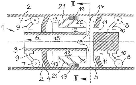
In Fig. 1, a cleaning pig referenced as a whole by 1 is shown in operation in
a
pipeline 2 that is, for example, a gas pipeline but basically can be also a
liquid
pipeline e.g. for long distance transportation of oil, water or liquid
chemicals.
Pipelines for long distance transportation of gas or crude oil are typically
divided into
long sections of, on average, 70 kilometers but can also have sections of
several
hundred kilometers through which cleaning pigs - like separating pigs for
delimiting
charges of fluid materials to be sequentially conveyed in the pipeline or also
measuring pigs for monitoring the pipeline 2 - must pass before they are
stopped
in a station, removed and checked.
The cleaning pig of the kind considered in this context has usually a
supporting pig
body 3 from which at least two spaced-apart collars 4,5, consisting of an
elastic but
highly wear-resistant material, such as polyurethane, project radially
outwardly so
as to rest against the innerwall of the pipeline. These collars 4, 5, on the
one hand,
close off the pipeline cross-section to such an extent that the cleaning pig 1
"cruises" together with the fluid material transported in the pipeline, i.e.,
experiences
at the rear an adequate pressure in comparison to the front end in the travel
direction so that it overcomes the friction on the pipeline wall as well as
the inertia
- 3 -
CA 02637791 2013-04-17
of mass of the pig and also possible gravitational effects at inclined
sections of such
a pipeline.
The collars 4, 5, as is known in the art, are essentially disk-shaped and in
the
present case of the cleaning pig 1, relative to the travel direction indicated
by the
arrow 6, are slightly dished and outwardly fleeing in order to reduce the
gliding
movement of the collars relative to the inner wall of the pipeline and in
order to
improve the sealing contact provided by the rearward pressure of the fluid
material.
While in simple pig configurations the collars also provide the centering and
supporting action for the pig 1 relative to the inner wall, in the present
case wheels
7 are provided on the lead end of the pig 1 and wheels 8 on the trail end of
the pig
1 that extend toward the inner side of the pipeline 2 on adequately yielding
wheel
supports 9 and 10 and in this way support and center the pig.
Such a centering and supporting action is in particular preferred when a great
wear
of the collars 4, 5 for large section lengths of the pipeline 2 and in
particular for
highly abrasive coatings on the inner side of the inner walls of the pipeline
are to be
expected. This can be the case, for example, in long-distance gas pipelines
with
dust deposits in the pipeline that are engaged and carried away only
unsatisfactorily
by the collars and cause great wear on the collars so that their contact on
the
pipeline will become defective. In this way, the cleaning effect as well as
advancing
of the cleaning pig become questionable.
The cleaning pig 1 has a special device that serves for detaching and removing
deposits, in particular, dust-like deposits from the pipeline. In this
respect, the pig
1 has an annular pressure opening 11 on the trail end that is cut out between
the
pig body 3 and the collar 5 and that is connected via pressure conduit 12 in
the form
of an annular chamber to a jet opening 13 that is directed against the inner
wall of
the pipeline 2. The jet opening can be designed like an annular radially
outwardly
oriented opening. It is understood that alternatively also a ring arrangement
of
- 4 -
CA 02637791 2013-04-17
individual openings can be provided. Instead of having a slightly widening
shape,
the jet opening 13 can be designed to have a narrowed shape as a jet in order
to
direct a pointed jet onto the inner wall of the pipe.
The deposits that are removed from the inner wall of the pipe by means of the
jet
opening 13 are removed by a suction device 14, arranged in the travel
direction
behind the jet opening 13, by means of a stream of the fluid material and are
transported by means of a suction conduit 15 extending centrally and forwardly
through the pig body 3 to a suction outlet at the lead end. In this way, a
flow-
through action through the cleaning pig 1 from the pressure opening 11 to the
suction outlet results wherein the suction outlet in the travel direction is
arranged
before the pressure opening. However, the flow passing through the area
between
the collars 4,5 in the travel direction is directed toward the rear. This
facilitates pick-
up of the removed deposits when, for example, in a gas pipeline a gas flow of
5 to
10 m/s is adjusted and the cleaning pig in comparison travels at a speed of 1
m/s
or less m/s.
The suction device 14 is formed by a ring arrangement of suction elements 17
that
are distributed annularly about the circumference of the pig and are connected
to
the suction conduit 15 by means of radial connectors 18 that pass through the
pressure conduit 12. It is understood that the suction elements 17 can also be
formed as an annular continuous suction device.
For assisting the removal of deposits from the pipeline 2 brushes can be
arranged
between the collars on the pig body 3; in the illustrated embodiment they are
mounted on an outer wall 20 of the pressure conduit 12 by means of a
parallelogram linkage 21 that also effects an elastic pressure action in the
outward
direction. These brushes 19 are also arranged in the travel direction in front
of the
suction device 14 so that the suction device 14 with the flow oriented toward
the
rear will also pick up the deposits that have been removed by the brushes 19.
- 5 -
CA 02637791 2008-07-18
Fig. 3 shows an embodiment of a cleaning pig 22 that with regard to different
elements corresponds to the preceding one wherein the coinciding elements are
identified with the same reference numerals as in Fig. 1 and are not explained
again
in the following. The special feature of this embodiment resides in an
enhanced
suction action. Instead of the simple centrally forwardly extending suction
conduit
15, the suction device 14 is connected by means of suction conduit 23 to a
venturi
tube 24 or a similarly acting fluidic suction generating device, for example,
in the
form of a jet pump or a blaster. The venturi tube 24 has an intake 25 that
narrows
like a jet and an outlet 26 that widens like a diffusor and is suitable with
an
intermediately positioned narrowed area of high flow rate and low pressure to
provide the desired high suction action for the suction device 14. This
increases
also the flow through the area between the collars from the jet opening 13 to
the
suction device 14 and improves thus the removal of detached floating deposit
particles. Even though the flow rate required for obtaining the suction
performance
causes a slowdown of the movement of the cleaning pig 22 relative to the
surrounding gas or fluid stream and is to be limited so as to provide reliable
advancing of the cleaning pig 22, it provides otherwise, as a result of the
great
speed difference between the fluid material transported in the pipeline and
the
cleaning pig, that deposits that have been detached are transported away so
that
they cannot collect in the pig area; such collection has been observed in
conventional cleaning pigs operating only with collars.
A further variant of a cleaning pig 27 according to Fig. 4 has a configuration
that is
substantially the same as that of the cleaning pig 22 according to Fig. 3 so
that
individual elements are also identified with same reference numerals. The
cleaning
pig 27 differs from the cleaning pig 22 in that the wheels 7, 8 for centering
and
supporting the cleaning pig 27 have brushes 28 in the leading area of the pig
and
brushes 29 in the trailing area, each outside of the longitudinal area that is
delimited
by the collars 4, 5; the brushes, arranged in a ring-shaped distribution about
the
circumference of the pig, are pressed with a springy action against the inner
wall of
the pipeline 2 and in this way develop an additional cleaning action. In this
- 6 -
_
CA 02637791 2008-07-18
connection, the brushes 28, 29 are supported by movable supports 30, 31 in a
yielding way in order to be able to adjust to the pipeline in the sense of
providing
uniform pressure in case of wear or in case of changing configurations of the
inner
pipeline cross-section.
- 7 -