Language selection

Search

Patent 2637872 Summary

Third-party information liability

Some of the information on this Web page has been provided by external sources. The Government of Canada is not responsible for the accuracy, reliability or currency of the information supplied by external sources. Users wishing to rely upon this information should consult directly with the source of the information. Content provided by external sources is not subject to official languages, privacy and accessibility requirements.

Claims and Abstract availability

Any discrepancies in the text and image of the Claims and Abstract are due to differing posting times. Text of the Claims and Abstract are posted:

  • At the time the application is open to public inspection;
  • At the time of issue of the patent (grant).
(12) Patent: (11) CA 2637872
(54) English Title: TARGET MARKING MUNITION
(54) French Title: MUNITIONS A MARQUAGE DE CIBLE
Status: Granted
Bibliographic Data
(51) International Patent Classification (IPC):
  • F42B 8/12 (2006.01)
  • F42B 8/20 (2006.01)
  • F42B 12/40 (2006.01)
(72) Inventors :
  • PANKNIN, FERDINAND (Germany)
  • BLACHE, ANDREAS (Germany)
  • BIPPES, BERND MICHAEL (Germany)
  • KOEPF, MICHAEL (Germany)
(73) Owners :
  • RHEINMETALL WAFFE MUNITION GMBH (Germany)
(71) Applicants :
  • RHEINMETALL WAFFE MUNITION GMBH (Germany)
(74) Agent: SMART & BIGGAR LP
(74) Associate agent:
(45) Issued: 2017-05-02
(22) Filed Date: 2008-07-16
(41) Open to Public Inspection: 2009-01-20
Examination requested: 2013-02-21
Availability of licence: N/A
(25) Language of filing: English

Patent Cooperation Treaty (PCT): No

(30) Application Priority Data:
Application No. Country/Territory Date
10 2007 034 546.3 Germany 2007-07-20

Abstracts

English Abstract

In order to mark the point at which a projectile (10, 11) strikes a target, a container (3) that holds an agent to mark the target is incorporated into the ogive area of the projectile (10, 11). When the projectile (10, 11) strikes the target, the container (3) is broken so that the marking agent can escape through holes (2) made in the ogive (4) or the rear section. In order that the marking agent can escape in this form, an over-pressure is generated within the projectile (10, 11). This can be done by a gas cartridge (7) with a release mechanism (8) or by a plunger (9).


French Abstract

Pour marquer le point auquel un projectile (10, 11) frappe une cible, un contenant (3) renfermant un agent destiné à marquer la cible est incorporé dans la zone ogivale du projectile (10, 11). Lorsque le projectile (10, 11) frappe la cible, le contenant (3) se brise afin que lagent de marquage puisse séchapper par des trous (2) pratiqués dans logive (4) ou la partie arrière. Pour que lagent de marquage puisse séchapper sous cette forme, une surpression est générée à lintérieur du projectile (10, 11). Cela peut être accompli au moyen dune cartouche de gaz (7) comportant un mécanisme de libération (8) ou par un plongeur (9).

Claims

Note: Claims are shown in the official language in which they were submitted.

CLAIMS:
1. A projectile with a tracer substance for marking the impact point of the

projectile on a target, at least one container being integrated in the ogive
region of the
projectile containing at least one means for marking the target, and the
container being
destroyed as the projectile impacts the target, wherein the means for marking
emerges via
bores introduced in the ogive or in the rear region, for which purpose
overpressure is
generated in the projectile, wherein the container is destroyed by a gas
cartridge located in
front of it that is pierced by the trigger mechanism, and the gas cartridge
generates the
overpressure.
2. A projectile with a tracer substance for marking the impact point of the

projectile on a target, at least one container being integrated in the ogive
region of the
projectile containing at least one means for marking the target, and the
container being
destroyed as the projectile impacts the target, wherein the means for marking
emerges via
bores introduced in the ogive or in the rear region, for which purpose
overpressure is
generated in the projectile, wherein the container is destroyed by a piston
located in front of it,
the piston generating the overpressure.
3. The projectile as set forth in claim 2, wherein the piston is displaced
axially by
a gas cartridge in order to build up the internal pressure.
4. The projectile as set forth in claim 2, wherein the piston is displaced
axially by
mechanical means in order to build up the internal pressure.
5. The projectile as set forth in claim 4, wherein the piston is displaced
by a
defined deformation of the projectile body.
6. The projectile as set forth in any one of claims 1 to 5, wherein two
containers
are integrated.
7. The projectile as set forth in any one of claims 1 to 6, wherein the
means for
marking is a powder.
4

8. The projectile as set forth in any one of claims 1 to 7, wherein the
means for
marking is a fluid.
9. The projectile as set forth in claim 8, wherein the fluid is a
luminescent fluid.
10. The projectile as set forth in any one of claims 1 to 8, wherein a
primer is
integrated at the tip of the ogive.
11. The projectile as set forth in any one of claims 1 to 10, wherein the
ogive
contains an inert mass.
12. The projectile as set forth in any one of claims 1 to 11, wherein it is
a practice
projectile.

Description

Note: Descriptions are shown in the official language in which they were submitted.


CA 02637872 2015-08-19
31512-2
Target Marking Munition
The present invention relates to a target marking munition, in particular for
mortars
and artillery.
Because of the use of training munitions that mark targets by pyrotechnic
means
(hot, burning particles) or if live munitions such as high explosive, smoke,
and
illuminating munitions, are used, there is a danger that fires, in particular
ground
fires, will be started. So-called forest fires in the area also play a role in
such
situations.
In order to conduct exercises in areas of this kind, inert projectiles that
have no
teiminal effect are used. This is problematic, particularly in the case of
target
practice that involve observers in the area of the target, since it is
impossible or
extremely difficult to locate the point of impact of the projectile. Thus it
is made
difficult for the observer to report back to the weapon crew and enable them
to aim
the weapon.
DE 10 2005 053 Al describes a projectile that marks the point of impact. This
training projectile has a hollow ogive that accommodates a first, chemically
inactive
and a second, chemically active marking agent. The first marking agent
generates a
colour effect, and the second marking agent generates a light effect. The
ogive itself
must burst in order for this to happen.
It is the objective of the present invention to create a munition that marks
the point
of impact in a simple manner by temporary visual marking.
The present invention is based on the idea that in order to mark the point of
impact
of a projectile at a target, a container (3) is incorporated in the ogive area
of the
1

CA 02637872 2015-08-19
31512-2
projectile. This container holds an agent to mark the target. When the
projectile strikes the
target, the container is broken so that the agent that marks the target can
escape through holes
in the ogive or in the rear of the projectile. In order that it can escape in
this form, an over-
pressure is generated within the projectile. This pressure can be generated by
a gas cartridge
with a release mechanism, or by a plunger or the like.
The body of the projectile incorporates a plunger or a gas cartridge that
generates internal
pressure when the projectile impacts and a liquid that is preferably
luminescent is expelled
through holes. This liquid is characterized in that it can be used for marking
targets by day or
by night.
The plunger is displaced either by the gas cartridge or mechanically by
deformation
(preferably defined), axially to the build-up of the internal pressure. The
gas cartridge is
punctured by a release mechanism that is, in its turn, punctured directly when
the projectile
impacts or by a detonator. The container that holds the liquid releases the
liquid through holes
in the ogive or in the base of the projectile so as to mark the target. The
mass, which is
preferably luminescent, is released without pyrotechnic means or damage to the
body of the
projectile with the fragmentation. The defined deformation of the plunger can
be effected by a
detonator that is incorporated in the base of the projectile.
The advantages are that there is no more danger of fires being started and
that the visibility of
the wreath-like point of impact is good in both daylight and in darkness,
without the need to
generate colour marking and a light effect. Furthermore, fragmentation of the
ogive is not
necessary. The projectile is simple and safe to handle and is the ballistic
equivalent of existing
projectiles.
In some embodiments, there is provided a projectile with a tracer substance
for marking the
impact point of the projectile on a target, at least one container being
integrated in the ogive
region of the projectile containing at least one means for marking the target,
and the container
being destroyed as the projectile impacts the target, wherein the means for
marking emerges
via bores introduced in the ogive or in the rear region, for which purpose
overpressure is
generated in the projectile, wherein the container is destroyed by a gas
cartridge located in
2

CA 02637872 2015-08-19
31512-2
front of it that is pierced by the trigger mechanism, and the gas cartridge
generates the
overpressure.
In some embodiments, there is provided a projectile with a tracer substance
for marking the
impact point of the projectile on a target, at least one container being
integrated in the ogive
region of the projectile containing at least one means for marking the target,
and the container
being destroyed as the projectile impacts the target, wherein the means for
marking emerges
via bores introduced in the ogive or in the rear region, for which purpose
overpressure is
generated in the projectile, wherein the container is destroyed by a piston
located in front of it,
the piston generating the overpressure.
The present invention will be described in greater detail below on the basis
of embodiments
shown in the drawings appended hereto. These drawings show the following:
2a

CA 02637872 2008-07-16
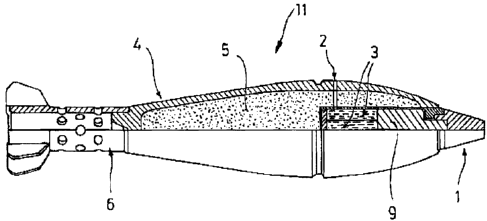
Figure 1: a projectile with a gas cartridge, in cross section;
Figure 2: a projectile with a plunger, in cross section.
Figure 1 shows a projectile 10, in this instance a training mortar bomb, with
a gas
cartridge 7 and release mechanism 8 for the cartridge 7 in a stylized cross
section. A
detonator bears the number 1. One hole, or preferably a plurality of holes, is

numbered 2, and a container is numbered 3. In this case, the container 3 holds
a
liquid. This is enclosed by an ogive 4 that protects the complete system and
also
accommodates an inert mass 5 that serves to ensure ballistic equivalence.
Within
the rear section 6, as in a mortar bomb, there are various holes through which
a
propellant charge (not shown in detail herein) is ignited.
It is preferred that the holes 2 be spaced equidistantly around the periphery
of the
ogive 4 or in the rear section of the projectile.
Figure 2 shows another projectile 11 that is also a practice mortar bomb that
instead
of the gas cartridge 7 and release mechanism 8 incorporates a plunger 9. These

function as follows:
When the projectile 10 or 11 impacts, the shock generated by the impact causes
the
gas cartridge 7 with the release mechanism to be punctured or the plunger to
be
moved. The liquid container 3 is destroyed by the over-pressure within the
projectile 10, 11. The liquid contained therein, which is preferably
luminescent,
mixes as it leaves the ogive 4 through the holes 2. As a result of this, the
target
within the target area is marked for all practical purposes simultaneously as
the
projectile 10, 11 impacts and is thereby indicated to an observer (not shown
herein).
A detonator is incorporated in the rear area of the ogive 4 so as to assist
the function
of the gas cartridge 7 or the plunger 9.
3

Representative Drawing
A single figure which represents the drawing illustrating the invention.
Administrative Status

For a clearer understanding of the status of the application/patent presented on this page, the site Disclaimer , as well as the definitions for Patent , Administrative Status , Maintenance Fee  and Payment History  should be consulted.

Administrative Status

Title Date
Forecasted Issue Date 2017-05-02
(22) Filed 2008-07-16
(41) Open to Public Inspection 2009-01-20
Examination Requested 2013-02-21
(45) Issued 2017-05-02

Abandonment History

Abandonment Date Reason Reinstatement Date
2014-08-19 R30(2) - Failure to Respond 2015-08-19

Maintenance Fee

Last Payment of $473.65 was received on 2023-07-03


 Upcoming maintenance fee amounts

Description Date Amount
Next Payment if small entity fee 2024-07-16 $253.00
Next Payment if standard fee 2024-07-16 $624.00

Note : If the full payment has not been received on or before the date indicated, a further fee may be required which may be one of the following

  • the reinstatement fee;
  • the late payment fee; or
  • additional fee to reverse deemed expiry.

Patent fees are adjusted on the 1st of January every year. The amounts above are the current amounts if received by December 31 of the current year.
Please refer to the CIPO Patent Fees web page to see all current fee amounts.

Payment History

Fee Type Anniversary Year Due Date Amount Paid Paid Date
Application Fee $400.00 2008-07-16
Maintenance Fee - Application - New Act 2 2010-07-16 $100.00 2010-06-22
Maintenance Fee - Application - New Act 3 2011-07-18 $100.00 2011-06-22
Maintenance Fee - Application - New Act 4 2012-07-16 $100.00 2012-06-22
Request for Examination $800.00 2013-02-21
Maintenance Fee - Application - New Act 5 2013-07-16 $200.00 2013-06-20
Maintenance Fee - Application - New Act 6 2014-07-16 $200.00 2014-06-19
Maintenance Fee - Application - New Act 7 2015-07-16 $200.00 2015-06-19
Reinstatement - failure to respond to examiners report $200.00 2015-08-19
Maintenance Fee - Application - New Act 8 2016-07-18 $200.00 2016-06-22
Final Fee $300.00 2017-03-14
Maintenance Fee - Patent - New Act 9 2017-07-17 $200.00 2017-07-03
Maintenance Fee - Patent - New Act 10 2018-07-16 $250.00 2018-07-02
Maintenance Fee - Patent - New Act 11 2019-07-16 $250.00 2019-07-08
Maintenance Fee - Patent - New Act 12 2020-07-16 $250.00 2020-07-06
Maintenance Fee - Patent - New Act 13 2021-07-16 $255.00 2021-07-05
Maintenance Fee - Patent - New Act 14 2022-07-18 $254.49 2022-07-04
Maintenance Fee - Patent - New Act 15 2023-07-17 $473.65 2023-07-03
Owners on Record

Note: Records showing the ownership history in alphabetical order.

Current Owners on Record
RHEINMETALL WAFFE MUNITION GMBH
Past Owners on Record
BIPPES, BERND MICHAEL
BLACHE, ANDREAS
KOEPF, MICHAEL
PANKNIN, FERDINAND
Past Owners that do not appear in the "Owners on Record" listing will appear in other documentation within the application.
Documents

To view selected files, please enter reCAPTCHA code :


To view images, click a link in the Document Description column. To download the documents, select one or more checkboxes in the first column and then click the "Download Selected in PDF format (Zip Archive)" or the "Download Selected as Single PDF" button.

List of published and non-published patent-specific documents on the CPD .

If you have any difficulty accessing content, you can call the Client Service Centre at 1-866-997-1936 or send them an e-mail at CIPO Client Service Centre.


Document
Description 
Date
(yyyy-mm-dd) 
Number of pages   Size of Image (KB) 
Description 2008-07-16 3 125
Abstract 2008-07-16 1 15
Claims 2008-07-16 1 31
Drawings 2008-07-16 1 25
Representative Drawing 2009-01-09 1 10
Cover Page 2009-01-15 1 38
Claims 2015-08-19 2 50
Description 2015-08-19 4 151
Claims 2016-06-06 2 55
Assignment 2008-07-16 3 105
Prosecution-Amendment 2013-02-21 2 74
Prosecution-Amendment 2014-02-19 2 71
Examiner Requisition 2015-12-07 3 198
Correspondence 2015-01-15 2 54
Amendment 2015-08-19 11 399
Amendment 2016-06-06 4 145
Final Fee 2017-03-14 2 75
Cover Page 2017-03-29 1 38