Note: Descriptions are shown in the official language in which they were submitted.
CA 02637961 2008-07-16
07-0546
ALIGNING A MACHINE TOOL WITH A TARGET LOCATION ON A
STRUCTURE
FIELD
[0001] The present disclosure relates generally to machine tooling
for the construction and assembly of structures and more particularly (but not
exclusively) to aligning a machine tool such as a drill or cutting tool with a
target location in a structure.
BACKGROUND
[0002] The statements in this section merely provide background
information related to the present disclosure and may not constitute prior
art.
[0003] In the construction of aircraft, two or more parts may be
spliced together to form an airframe section. One part typically is overlaid
onto
another, and holes may be drilled through the aligned parts to accommodate
fasteners. Driliing locations in the parts are typically selected in
accordance
with nominal design specifications. In some splicing applications, drill jigs
may
be used to guide a drilling tool to the nominal drilling locations.
SUMMARY
[0004] The present disclosure, in one configuration, is directed to an
apparatus for aligning a machine tool with a target location on a structure.
The apparatus includes a machine plate positionable on the structure. The
plate has a plate bushing that provides a hole through the machine plate. The
apparatus also includes a nosepiece for guiding a distal end of the tool
through the plate bushing to the target location. The nosepiece has a collet
configured to be moved at least partly through and sideward in the plate
bushing to center the nosepiece on an element projecting from the structure
at the target location. The nosepiece is configured for attachment to the
plate
bushing to establish a predefined approach angle of the tool relative to the
projecting element.
1
CA 02637961 2008-07-16
07-0546
[0005] In another configuration, the disclosure is directed to a
machine assembly including a machine tool and an apparatus for aligning a
distal end of the machine tool with a target location on a structure. The
apparatus includes a machine plate positionable on the structure and having
one or more plate bushings each providing a hole through the machine plate.
The apparatus also includes a nosepiece for guiding the tool distal end
through the plate bushing to the target location when the plate bushing is
placed over the target location. The nosepiece has a housing and a collet
attached to and extending distally from the housing. The collet has a distal
end configured to pass through the plate bushing. The collet is further
configured to be moved radially in the plate bushing to center the nosepiece
over an element projecting from the structure at the target location. The
housing is configured for attachment to the plate bushing to establish
normality of the tool relative to the projecting element.
[0006] In another implementation, the disclosure is directed to a
method of aligning a machine tool with a target location on a structure. A
distal end of the machine tool is inserted into a nosepiece for guiding a
distal
end of the tool. The nosepiece has a housing and a collet attached to and
extending distally from the housing. The method includes inserting a distal
end of the collet through a plate bushing in a machine plate positioned over
an element projecting from the structure at the target loaation. The collet is
moved radially in the plate bushing to center the collet distal end over the
element projecting from the structure. The method inoludes affixing the
centered collet distal end to the projecting element, and aOixing a distal end
of
the housing to the plate bushing.
[0007] In yet another configuration, the disclosure is directed to a
machine plate for use with a machine tool. The machino plate has a body
including at least one plate bushing having a hole positibnable relative to a
target location on a structure. The plate bushing includes rim graspable by a
nosepiece through which the machine tool is operable. he plate bushing is
configured to allow passage therethrough of a distal end of a collet attached
to the nosepiece. The plate bushing is further config red to allow radial
2
CA 02637961 2008-07-16
07-0546
movement of the collet therein for centering of the collet~ over an element
projecting from the structure at the target location. The plate bushing is
further
configured to establish a predefined angle of approach by the machine tool
relative to the projecting element when the nosepiece has grasped the rim of
the plate bushing.
9. A machine assembly comprising:
a machine tool; and
an apparatus for aligning a distal end of the machine tool with a target
location on a structure, the apparatus including a machine plate positionable
on the structure and having one or more plate bushings each providing a hole
through the machine plate, and a nosepiece for guiding the tool distal end
through the plate bushing to the target location when the plate bushing is
placed over the target location, the nosepiece having a housing and a collet
attached to and extending distally from the housing;
the collet having a distal end configured to pass through the plate
bushing;
the collet further configured to be moved radially in the plate bushing to
center the nosepiece over an element projecting from the structure at the
target location;
the housing configured for attachment to the plate bushing to establish
normality of the tool relative to the projecting element.
10. The machine assembly of claim 9, the housing having a
distal end configured to be fitted over the plate bushing.
11. The machine assembly of claim 9, the nosepiece further
comprising a clamp operable to clamp the collet onto the projecting element.
12. The machine assembly of claim 9, the nosepiece further
comprising a clamp and a piston operable to push the cl mp at least partially
through the housing to clamp the collet onto the projecti g element and the
housing onto the plate bushing.
3
CA 02637961 2008-07-16
07-0546
13. The machine assembly of claim 12, wherein the piston is
attached to the clamp.
14. The machine assembly of claim 9, the plate bushing
comprising a proximal rim configured to mate with a distal end of the housing.
15. The machine assembly of claim 9, further comprising a
machining module affixed to the apparatus and operable to actuate the
machine tool.
16. The machine assembly of claim 15, wherein the
machining module includes an orbital drill unit.
22. A machine plate for use with a machine tool, the machine
plate comprising a body including at least one plate bushing having a hole
positionable relative to a target location on a structure;
the plate bushing comprising a rim graspable by a nosepiece through
which the machine tool is operable, the plate bushing configured to allow
passage therethrough of a distal end of a collet attached to the nosepiece,
the
plate bushing further configured to allow radial movement of the collet
therein
for centering of the collet over an element projecting from the structure at
the
target location;
the plate bushing further configured to establish a predefined angle of
approach by the machine tool relative to the projecting element when the
nosepiece has grasped the rim of the plate bushing.
23. The machine plate of claim 22, wherein the plate bushing
is configured to allow the collet to be centered over a bushing in a hole in
the
structure.
4
CA 02637961 2008-07-16
07-0546
24. The machine plate of claim 22, wher~in the rim of the
plate bushing comprises a plurality of lobes configured'to mate with the
nosepiece.
[0008] Further areas of applicability will become apparent from the
description provided herein. It should be understood that the description and
specific examples are intended for purposes of illustration only and are not
intended to limit the scope of the present disclosure.
BRIEF DESCRIPTION OF THE DRAWINGS
[0009] The drawings described herein are for illustration purposes
only and are not intended to limit the scope of the present disclosure in any
way.
[0010] Figure 1 is a cross sectional view of a structure in relation to
which an apparatus for aligning a machine tool may be used in accordance
with one implementation of the disclosure;
[0011] Figure 2 is a top perspective view of a machine plate in
accordance with one implementation of the disclosure;
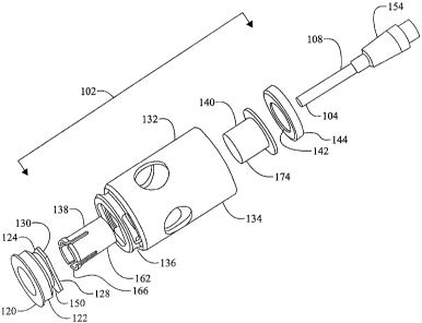
[0012] Figure 3 is an exploded side perspective view of a nosepiece
and plate bushing in accordance with one implementation of the disclosure;
[0013] Figure 4 is a perspective view of a plate bushing in
accordance with one implementation of the disclosure;
[0014] Figure 5 is a perspective view of a distal !end of a nosepiece
housing in accordance with one implementation of the discMosure;
[0015] Figure 6 is a side view of a nosepiece Ottached to a plate
bushing in accordance with one implementation of the disc osure;
[0016] Figure 7 is a longitudinal sectional view o a nosepiece and a
plate bushing in accordance with one implementation of the disclosure, the
nosepiece shown in an unciamped position;
[0017] Figure 8 is a top plan view of a plate bus ing centered over a
target bushing in accordance with one implementation of t e disclosure;
5
CA 02637961 2008-07-16
07-0546
[0018] Figure 9 is a side perspective view f a nosepiece in
clamped position in accordance with one implementation of;the disclosure;
[0019] Figure 10 is a flow diagram of aircraft production and service
methodology;
[0020] Figure 11 is a block diagram of an aircraft;
[0021] Figure 12 is a block diagram of an apparatus for aligning a
machine tool with a target location on a structure in clamped position in
accordance with one implementation of the disclosure; and
[0022] Figure 13 is a flow diagram of a method of aligning a
machine tool with a target location on a structure in accordance with one
implementation of the disclosure.
DETAILED DESCRIPTION
[0023] The following description is merely exemplary in nature and
is not intended to limit the present disclosure, application, or uses. It
should
be understood that throughout the drawings, corresponding reference
numerals indicate like or corresponding parts and features.
[0024] Referring more particularly to the drawings, embodiments of
the disclosure may be described in the context of an aircraft manufacturing
and service method 60 as shown in Figure 10 and an aircu-aft 80 as shown in
Figure 11. During pre-production, exemplary method 60 may include
specification and design 62 of the airdraft 80 and materiral procurement 64.
During production, component and subassembly manjufacturing 66 and
system integration 68 of the aircraft 80 takes place. There'~fter, the
aircraft 80
may go through certification and delivery 70 in order to ble placed in service
72. While in service by a customer, the aircraft 80 is s~heduled for routine
maintenance and service 74 (which may also in~lude modification,
reconfiguration, refurbishment, and so on).
[0025] Each of the processes of method 60 m y be performed or
carried out by a system integrator, a third party, and/or n operator (e.g., a
customer). For the purposes of this description, a syslem integrator may
6
CA 02637961 2008-07-16
07-0546
include without limitation any number of aircraft manufa turers and major-
system subcontractors; a third party may include wit out limitation any
number of venders, subcontractors, and suppliers; and an operator may be an
airline, leasing company, military entity, service organization, and so on.
[0026] As shown in Figure 11, the aircraft 80 produced by
exemplary method 60 may include an airframe 82 with a plurality of systems
84 and an interior 86. Examples of high-level systems 84 include one or more
of a propulsion system 88, an electrical system 90, a hydraulic system 92, and
an environmental system 94. Any number of other systemis may be included.
Although an aerospace example is shown, the principles of the invention may
be applied to other industries, such as the automotive industry.
[0027] Apparatus and methods embodied herein may be employed
during any one or more of the stages of the production and service method
60. For example, components or subassemblies corresponding to production
process 66 may be fabricated or manufactured in a manner similar to
components or subassemblies produced while the aircraft 80 is in service.
Also, one or more apparatus embodiments, method embodiments, or a
combination thereof may be utilized during the production stages 66 and 68,
for example, by substantially expediting assembly of or reducing the cost of
an aircraft 80. Similarly, one or more of apparatus embodiments, method
embodiments, or a combination thereof may be utilized while the aircraft 80 is
in service, for example and without limitation, to maintenance and service 74.
[0028] In various implementations, the present disclosure is directed
to methods and apparatus for aligning a machine tool with a target location on
a structure. The machine tool may be operable, for example, using an orbital
drilling unit or other machining module. Various implementations of the
disclosure make it possible to perform machining at a target location that
could deviate from a nominal machining location.
[0029] A block diagram of one configuration of an apparatus for
aligning a machine tool with a target location on a structure is indicated
generally in Figure 12 by reference number 200. The appiaratus 200 includes
a machine plate 204 positionable on the structure. Th~ plate has a plate
7
CA 02637961 2008-07-16
07-0546
bushing 208 that provides a hole through the machine plate 204. The
apparatus also includes a nosepiece 212 for guiding a distal end of the tool
(not shown) through the plate bushing 208 to the target IoCation (not shown).
The nosepiece 212 has a collet 216 configured to be moved at least partly
through and sideward in the plate bushing 208 to center the nosepiece 212 on
an element (not shown) projecting from the structure at the target location.
The nosepiece 212 is configured for attachment to the plate bushing 208 to
establish a predefined approach angle of the tool relative to the projecting
element.
[0030] It should be noted that the disclosure could be implemented
in connection with many types of machines and/or tools, including but not
limited to cutting machines and tools and non-orbital drills. Power feed or
positive feed drill motors, plasma cutting torches, water jet nozzles, laser
drilling and/or marking equipment, hole saws, broaching heads, and/or
various types of machining heads could be adapted for use in accordance
with the disclosure. Additionally, although various implementations may be
described with reference to splicing applications, the disclosure is not so
limited. The disclosure can be implemented in many appliications in which it
may be desirable to center a machine tool over a machining location and to
utilize the tool along a specific vector or approach angle relative to that
location.
[0031] An exemplary cross section of a structure in which splicing
may be performed is indicated generally in Figure 1 by reference number 20.
An orbital drilling unit may be used in accordance with one implementation of
the disclosure to drill, e.g., through several aligned parts 24. The parts 24
may
be made of different materials, including but not limited to carbon fiber
reinforced plastics, metals, etc. In the present example, drilling is to be
performed in a plurality of target locations 28, one of which is shown in
Figure
1. Drilling is to be performed along a path 30 through the parts 24, beginning
at the target location 28, which is defined by a bushing 32 that lines a hole
36
in an upper splice plate 40. Such a bushing may be referred to in this
disclosure and the claims as a "target bushing". Thus drilling may be
specified
8
CA 02637961 2008-07-16
07-0546
to be performed at a nominal location indicated gene~ally by reference
number 46. It should be noted, however, that the nominal drilling location 46
may or may not coincide exactly with the target location 28, dependent, e.g.,
on tolerances provided in the nominal drilling specification. A flange 50 of
the
target bushing 32 projects from an upper surface 54 of the structure 20.
[0032] Various configurations of an apparatus for aligning a
machine tool with a target location on a structure include a machine plate and
a nosepiece, e.g., as shown in Figures 2 and 3. A target location may be, for
example, the target bushing 32 installed in the structure 20, and various
aligning apparatus configurations are described below with reference to the
structure 20 and target bushing 32. It should be noted, ho!wever, that various
implementations are contemplated in relation to other types of target
locations. For example, the presence of a hole is not necessary at a target
location for configurations of the apparatus to align a machine tool.
Additionally or alternatively, the disclosure could be implemented in relation
to
elements other than bushings that project from a structural surface, e.g. nail
heads, screw heads, etc. Although such projections could be circular and/or
spherical, they could have other or additional shapes.
[0033] One configuration of a machine plate is indicated generally in
Figure 2 by reference number 100. One configuration of a nosepiece is
indicated generally in Figure 3 by reference number 102. As further described
below, the nosepiece 102 may be used to guide a distal end 104 of a machine
tool 108 through the machine plate 100 to a target drilling location 28 on the
structure 20. The machine tool 108 is, e.g., a cutting tool operable via an
orbital drill unit (not shown in Figure 3). The terms "proximal" and "distal"
are
used with reference to a user of the machine tool 108.
[0034] Referring now to Figure 2, the machine plate 100 may be
positioned on and attached to the structure surface 54. The machine plate
100 has a body 112 made, for example, of solid aluminum that may be
elevated from the surface 54, e.g., by a plurality of supports 116. A
plurality of
plate bushings 120 are mounted in the machine plate body 112 to provide a
plurality of holes 118 through the body 112. Each bushing 120 may be
9
CA 02637961 2008-07-16
07-0546
positioned over a corresponding target drilling location on ~he structure 20.
In
the present exemplary configuration, the bushings 120 are configured to
establish normality of a machine tool relative to a target ilocation as
further
described below. In some other configurations, however, plate bushings may
be configured to establish an approach angle for a machine tool at other than
ninety degrees. It should be noted generally that machine plate configurations
of various shapes and having various dimensions and numbers of holes,
including configurations having a single hole, are contemplated.
[0035] In the present configuration, each plate bushing 120 has a
distal portion 122 fixedly mounted in the machine plate body 112 and a
proximal portion 124 extending above a proximal surface 126 of the machine
plate body 112. A plate bushing 120 may be made, e.g., of hardened tool
steel and is shown in greater detail in Figures 3 and 4. The plate bushing
proximal portion 124 has a projecting rim 128 that is graspable by the
nosepiece 102 as further described below. In the present configuration, the
bushing rim 128 includes a plurality of lobes 130.
[0036] Referring now to Figures 3, 5, 6 and 7, the nosepiece 102
includes a plurality of substantially concentric components, e.g., a housing
132 having a proximal portion 134 and a distal portion 136, a collet 138, a
collet clamp 140, a piston 142 and piston cylinder 144. The housing 132 may
be made from one solid piece of steel, e.g., heat treatable stainless or tool
steel. The piston 142 and cylinder 144 may be fabricated, e.g., of stainless
steel.
[0037] In the present configuration and as shown in Figures 4 and
5, the distal portion 136 of the nosepiece housing 132 isi configured to mate
with lobes 130 of the plate bushing 120. Specifically, an end 146 of the
distal
portion 136 has a hole 148 shaped to fit over the lobes 130 when a user
positions the nosepiece relative to the plate bushing 120. As further
described
below, a user may cause the nosepiece housing 132 to be locked onto the
lobes 130 through slots 152 and to be pressed against a distal surface 150
(shown in Figure 7) provided by the lobes 130.
CA 02637961 2008-07-16
07-0546
[0038] Referring now to Figures 3 and 6, the cutti~g tool 108 is held
by a tool holder 154 configured for attachment to an orbitall drill unit 156.
The
orbital drill unit 156 and attached cutting tool 108 may bd rigidly connected
with the nosepiece housing 132 at a plurality of housing flonges 158, two of
which are shown in Figure 6. In various configurations the tool holder 154
provides a standard interface, e.g., a HSK mount and heat shrink tool holder
interface, between the tool 108 and the orbital drilling unit 156. In other
configurations in which machining modules other than the present exemplary
orbital drill unit are used, other or additional types of tool' holder
interfaces,
e.g., CAT, SK, BT interfaces, may be used. The nosepiece housing 132
includes lateral holes 160 for chip evacuation via an external vacuum system
and duct (not shown).
[0039] A proximal portion 162 of the collet 138 is! rigidly fixed to the
nosepiece housing 132 through the piston cylinder 144. As shown in Figure
7, a slotted distal portion 164 of the collet extending from the housing 132
includes a lip 166. The collet may be made of a single pieae of material,
e.g.,
of heat treatable stainless or tool steel. Slots 178 allow the machined
diameter
of the contacting surface of the lip 166 to contract as the collet clamp 140
slides over the distal portion 164 of the collet. The lip 166 is configured to
fit
over the protruding flange 50 of the bushing 32. In other implementations, a
collet could be configured to fit over an element of a different type and/or
having a different shape projecting from a work piece surface.
[0040] The nosepiece 102 with integral collet 138 is configured for
radial movement in the plate bushing 120 to allow centering of the collet 138
with fixed nosepiece 102 on the target bushing flange 50. Accordingly,
dimensions of the plate bushing 120 are based on dimensions of the target
bushing 32 and collet 138, e.g., as shown in Figure 8. Figure 8 is a top plan
view of the plate bushing 120 centered over the target bushing 32. An inner
diameter 168 of the plate bushing 120 may be established by adding twice the
wall thickness of the collet 138 to an amount of leeway to a diameter 170 of
the target bushing flange 50. For example, where a leeway of 0.050 inches is
added to twice the collet wall thickness, the resulting plate bushing inner
11
CA 02637961 2008-07-16
07-0546
diameter 168 allows radial displacement of the collet 13~ by 0.025 inches
from a nominal drill location when the collet 138 is moved irr the plate
bushing
120 to center the nosepiece 102 on the target bushing flange 50. Thus, in the
present configuration, leeway for radial movement of the collet 138 is a
function of the difference in diameters 168 and 170 and the outside dimension
of the collet clamp 140 divided by two.
[0041] An outer diameter 172 of the plate bushing 120 may be, e.g.,
a standard size used in drill plate fabrication. In the present exemplary
configuration, the machine plate 100 and plate supports 11.6 are fabricated to
provide a machine plate height that allows each plate bushing 120 to be at an
appropriate height from the work piece surface 54 to ensure sufficient contact
by the collet 138 over the target bushing flange 50.
[0042] The collet clamp 140 has a distal end 174 configured to be
extended over the collet 138 to clamp the collet 138 onto the target bushing
flange 50. The clamp 140 may be made from a highly elastic material, e.g.,
acetal copolymer. Such material allows the collet 138 to close around a target
bushing flange within a predetermined vicinity of, e.g., pl!us or minus 0.010
inch diametric from, a nominal target bushing flange outside dimension and
still substantially close a gap 176 (shown in Figure 7) between the nosepiece
housing, plate bushing 120 and collet clamp 140.
[0043] An air hose 180 (shown in Figure 6) extending from an air
pressure/vacuum system (not shown) into the housing ;132 pneumatically
connects the pressure/vacuum system with a space 182 dlefined in the piston
cylinder 144. The piston 142 is rigidly attached to the clamp 140 and
operable to push the clamp 140 at least partially through ;the housing 132 to
clamp the collet 138 onto the target bushing flange 50 and the housing 132
onto the plate bushing 120. The housing 132 may be clamped onto the plate
bushing 120 and against the lobe distal surface 150 to establish normality of
the tool 108 relative to the target bushing flange 50.
[0044] A machine assembly that includes the foregoing aligning
apparatus may be combined with an orbital drill unit and used in the following
manner. A user installs the tool 108 in the tool holder 154 and installs the
tool
12
CA 02637961 2008-07-16
07-0546
holder 154 in the orbital drill unit 156. The user then affixes t e orbital
drill unit
to the proximal flanges 158 of the nosepiece housing 132 s that the tool 108
is extendable through the nosepiece 102. The machine plate 100 is positioned
over the structure 20 so that one or more plate bushings 120 are positioned
over one or more target drilling locations 28, e.g., over one or more target
bushing flanges 50 projecting from the structure surface 54, Placement of the
machine plate may be in accordance with nominal drilling location
specifications.
[0045] The user inserts the nosepiece 102 into a plate bushing 120
so that distal ends of the collet 138 and clamp 140 extend through the plate
bushing 120 toward a target bushing flange 50. To position the collet lip 166
around the target bushing flange 50, the user may "float" the drill unit
motor,
keeping the tool distal end 104 retracted from the plate bushing 120, and may
move the collet 138 longitudinally and/or sideward in the plate bushing until
the collet 138 is centered on the bushing flange 50. To position the nosepiece
102 relative to the plate bushing 120, the user may rotate the nosepiece,
e.g.,
up to about 60 degrees to mate the nosepiece hole 148 with the lobes 130 of
the plate bushing 120. When the nosepiece and lobes have been mated, the
piston 142 can be actuated toward the distal end of the housing 132 to lock
the plate bushing lobes 130 into the distal end 146 of the nosepiece housing
132. It should be noted that unless the collet 138 is positioned over and onto
the target bushing flange 50, the nosepiece 102 cannot be rotated and
therefore cannot be locked onto the plate bushing lobes 130. In such manner,
incorrect positioning of the collet onto the flange 50 can be avoided.
[0046] When the nosepiece 102 has been rotat d into position over
the plate bushing lobes 130, the user may activate ~he clamp 140 by
introducing gas or hydraulic pressure, e.g., air from the air pressure system
through the air hose 180 into the piston cylinder 144. Air pressure may be
supplied in the piston cylinder at between about 100 and 200 pounds per
square inch. In some configurations, air pressure as high as about 400
pounds per square inch could be supplied in the cylinder 144. The pressure
causes the piston 142 to push the clamp 140 distally in the piston cylinder
13
CA 02637961 2008-07-16
07-0546
144. The clamp 140 closes the collet 138 around the flang 50 of the target
bushing 32, centering the machine tool 108 and drill unit 1 6 over the target
bushing 32. The clamp also clamps the nosepiece 102 against the plate
bushing lobes 130. The nosepiece is forced against the liobe surface 150,
thereby bringing the machine tool 108 and drill unit 156 into normality with
the
target bushing 32. This double clamping action, caused by a single stroke of
the piston 142, restrains the nosepiece 102 and drill unit in the machine
plate
100 in six degrees of freedom. The drill unit 156 can then be used to drill
through the target bushing 32. The nosepiece 102 is shown in Figure 9 in
clamped position.
[0047] To remove the drill unit and nosepiece 102 from the machine
plate 100, the user activates the air system to create a vacuum in the piston
cylinder 144, thereby causing the piston 142 to withdraw the clamp 140 and
allow the nosepiece 102 to be removed from the target bushing flange 50 and
plate bushing lobes 130. It should be noted generally that the clamp 140
could be operated in other or additional ways. For example, manual operation
of a collet clamp is contemplated in some implementations. It also should be
noted that many different types of grasping mechanisms could be used in
place of the rim 128 and lobes 130. For example, the rim and/or nosepiece
distal end could include various contours instead of or in addition to flat
surfaces.
[0048] A flow diagram of a method of aligning a machine tool with a
target location on a structure in accordance with one implementation of the
disclosure is indicated generally in Figure 13 by reference number 300. In
step 304 the distal end of the machine tool is inserted into a nosepiece for
guiding a distal end of the tool. The nosepiece has a housing and a collet
attached to and extending distally from the housing. In step 308, a distal end
of the collet is inserted through a plate bushing in a machine plate
positioned
over an element projecting from the structure at the target location. In step
312 the collet is moved radially in the plate bushing to center the collet
distal
end over the element projecting from the structure. In step 316 the centered
14
CA 02637961 2008-07-16
07-0546
collet distal end is affixed to the projecting element. In step;320, a distal
end
of the housing is affixed to the plate bushing.
[0049] The foregoing apparatus and methods make it possible to
use nominal specifications to position a drill plate over a work piece and
then
to perform drilling based on the location of a "landmark" on the underlying
structure. Configurations of the machine plate and nosepiece interface make it
possible to achieve both concentricity and normality in hole processing. It is
possible for drilling to deviate from nominal locations while ensuring that a
final hole is processed concentric with a required target location, e.g., an
installed bushing. After a one-time installation of a drilling tool in the
nosepiece, the drill unit and nosepiece can be inserted into a plurality of
plate
bushings to drill a plurality of hole locations without having to reinstall
the tool
in the nosepiece or perform other time consuming steps.
[0050] A single-acting cylinder provides the force sufficient to close
the collet that finds the center of an installed work piece bushing and
provides
normality and rigidity for an orbital drill unit to process a hole. The center
line
of a hole is not determined by a drill bushing but rather by the location of
an
installed bushing or other projecting element on the structure. Using the
foregoing apparatus and methods can increase productivity and lower
production cycle times to produce high-quality holes.
[0051] The above aligning apparatus can be used in orbital drilling,
the benefits of which can include the ability to obtain a plurality of hole
diameters from a single cutter, low cutting forces, high surface-feet-per-
minute
machining of carbon fiber composite, stainless steel and/or titanium
structure,
minimal entry and/or exit burr and virtually no composite delamination. A
simple interface with an orbital drill motor is provided, along with the
ability to
quickly locate the centerline of a fastener. The "insert, rotate, and lock"
process to be followed by an operator is simple and quick to perform. The
process is highly visible to an operator, and since there is a dedicated plate
bushing size for each fastener diameter, errors can be reduced or eliminated.
[0052] While various embodiments have been described, those
skilled in the art will recognize modifications or variations which might be
CA 02637961 2008-07-16
07-0546
made without departing from the present disclosure. The examples illustrate
the various embodiments and are not intended to limit the present disclosure.
Therefore, the description and claims should be interpreted liberally with
only
such limitation as is necessary in view of the pertinent prior art.
16