Note: Descriptions are shown in the official language in which they were submitted.
CA 02638628 2008-08-12
Attorney Docket No. 38225/83313
COMBUSTION POWERED DRIVER
RELATED APPLICATIONS
The present application is related to and claims priority to U.S. Provisional
Patent Application, Serial No. 60/943,789, filed on June 13, 2007, entitled
Cornbustion
Powered Driver and U.S. Provisional Patent Application Serial No. 60/943.887
filed on
June 14, 2007, entitled Combustion Powered Driver. The entire subject matter
disclosed
in those provisional applications is hereby expressly incorporated by
reference into the
present application.
TECI-INICAL FIELD
This invention relates generally to an apparatus for driving an object,
including but not limited to a post driver, power shovel, log splitter, and
concrete breaker.
In some embodiments, the apparatus uses energy from the combustion of
combustible
fuel to drive the object.
BACKGROUNI)
Posts have many different purposes, such as for signs, fences, etc. In
some cases, a post may be installed by driving it into the ground. Although
posts were
originally manually driven into the ground, such as with a sledgehammer,
mechanical
post drivers are also known. Mechanical post drivers often include a heavy
hammer that
is raised and then dropped onto the post. Some post drivers include hydraulic
pressure or
-2-
i
CA 02638628 2008-08-12
Attorney Docket No. 38225/83313
a cable assembly to raise and drop the hammer. Although such post drivers
perform the
intended function, the heavy hammer reduces portability and requires a massive
support
structure. Therefore, there is a need for an improved driver.
SUMMARY
According to one aspect, the present invention provides an apparatus for
driving a post. The apparatus may have a driver body with a combustion
chamber. A
fuel injection valve may be provided that selectively controls the flow of
fuel into the
combustion chamber. 'The apparatus may include an ignition module adapted to
ignite
fuel within the combustion chamber. In some preferred embodiments, for
example, the
apparatus could use a readily available propane cylinder. A ram and piston may
be
provided that are movable within the driver body. The piston may be adapted to
impact
the ram in response to combustion within the combustion chamber. In some
embodiments, the ram may include a resilient portion that flexes when the
piston impacts
the ram. Embodiments are also contemplated with a valve that selectively
opens/closes a
passageway through the piston. According to a further embodiment, one or more
handles
may extend from the driver body. In some cases, the handles may include grip
portions
that are movable with respect to the handle. In some preferred embodiments,
for
example. the apparatus is self-contained and portable, which allows an easier
and more
efficient manner of driving a post.
According to another aspect, the invention provides a free piston internal
combustion engine. The engine would include a cylinder having a first end with
a first
-3-
i
CA 02638628 2008-08-12
Attorney Docket No. 38225/83313
projection and a second end with a second projection. A combustion chamber is
disposed
within the cylinder. An ignition module is provided for igniting fuel within
the
combustion chamber. 'The engine includes a piston movable within the cylinder
between
the first end and the second end. The piston moves toward the second end
responsive to
combustion in the combustion chamber. A passageway is defined through the
piston. A
biasing member is provided to urge the piston toward the first end of the
cylinder. The
engine includes a piston valve movable between an open position and a closed
position,
in which the piston valve prevents fluid flow though the passageway in the
closed
position, but allows fluid flow through the passageway in the open position.
Typically, at
least a portion of the piston valve is disposed within the piston. The piston
valve moves
to the closed position when a first end of the piston valve contacts the first
projection, but
moves to the open position when a second end of the piston valve contacts the
second
projection.
Additional features and advantages of the invention will become apparent
to those skilled in the art upon consideration of the following detailed
description of the
illustrated embodiment exemplifying the best mode of carrying out the
invention as
presently perceived.
BRIEF DESCRIPTION OF THE DRAWINGS
The present disclosure will be described hereafter with reference to the
attached drawings which are given as non-limiting examples only, in which:
-4-
CA 02638628 2008-08-12
Attorney Docket No. :3 8225/83313
Figure 1 is a perspective view of a post driver according to an embodiment
of the invention;
Figure 2 is a top cross-sectional view of the post driver shown in Figure 1;
Figure 3 is a side cross-sectional view of the post driver shown in Figure 1
with the piston in an initial position;
Figure 4 is a detailed side cross-sectional view of the upper portion of the
post driver showing the primer valve in an open position;
Figure 5 is a side cross-sectional view of the upper portion of the post
driver showing the primer valve in an open position;
Figure 6 is a side cross-sectional view of the post driver shown in Figure 1
piston in a priming position;
Figure 7 is a side cross-sectional view of the post driver shown in Figure 1
with the piston impacting the ram;
Figure 8 is a side cross-sectional view of the post driver shown in Figure 1
with the piston impacting the cylinder head;
Figure 9 is a perspective view of the piston shown in Figure 3 with the
upper member removed;
Figure 10 is a top view of the piston shown in Figure 3 with the upper
member removed;
Figure 1 1 is a side cross-sectional view of the piston shown in Figure 3:
Figure 12 is a detailed cross-sectional view of the post driver shown in
Figure 1;
-5-
I
CA 02638628 2008-08-12
Attorney Docket No. 38225/83313
Figure 13 is a side cross-sectional view of the ram according to, another
embodiment;
Figure 14 is an exploded view of the ram shown in Figure 13 to show the
optional drive collar;
Figure 15 is a detailed perspective view of the post driver shown in Figure
1
Figure 16 is a side view of the post driver shown in Figure 1.
Corresponding reference characters indicate corresponding parts
throughout the several views. The exemplification set out herein illustrates
example
embodiments of the invention, and such exemplification is not to be construed
as limiting
the scope of the invention in any manner.
DETAILED DESCRIPTION OF THE DRAWINGS
It is to be understood by one of ordinary skill in the art that the present
discussion is a description of exemplary embodiments only, and is not intended
as
limiting the broader aspects of the present invention, which broader aspects
are embodied
in the exemplary constructions.
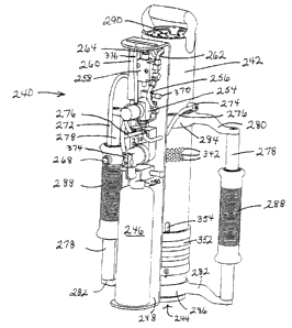
Figure 1 shows a post driving apparatus, generally referred to by reference
number 240. In the example shown, the post driving apparatus 240 has a driver
body
242. Although the driver body 242 is cylindrical in the example shown, the
body could
have a square, oval, or other cross-sectional shape. The driver body 242 may
be formed
from steel, aluminum, fiberglass, or any other suitable rigid material. The
lower end 244
-6-
I
CA 02638628 2008-08-12
Attorney Docket No. 3 8225/833 13
of the driver body 242 is adapted to receive a post to be driven, as described
below. The
apparatus 240 may drive wooden posts, metal posts, fiberglass posts, or other
types of
posts. The apparatus 240 may drive round posts, square posts, U-channel posts,
or other
post shapes. Embodiments are also contemplated in which the apparatus could be
adapted for driving a power shovel. By way of another example, embodiments are
contemplated in which the apparatus could be adapted to split logs or break
concrete.
One skilled in the art should appreciate that the system could be adapted to
reciprocately
drive any object.
The apparatus 240 drives a post using energy generated by the combustion
of fuel. The term "fuel" is broadly intended to encompass any ignitable fluid,
such as
liquefied petroleum ("LP") gas, natural gas, or gasoline. For purposes of
example only,
the fuel may include propane, butane, isobutene, methylacetylene-propadiene
("MAPP"),
or acetylene. A fuel reservoir 246 is adapted to hold a quantity of fuel. In
the
embodiment shown, the fuel reservoir 246 is carried by a mounting shelf 248,
which is
coupled to the driver body 242. A cover (Figure 16) may be provided over the
mounting
shelf for safety purposes. In some cases, the fuel reservoir 246 could be
refillable;
alternatively, the fuel reservoir 246 may be disposable. For example, the fuel
reservoir
246 could be a readily available propane cylinder.
In the example shown, the top end of the fuel reservoir 246 defines a fuel
outlet port 250 through which fuel may exit the fuel reservoir 246. In some
cases, such
as when liquefied petroleum gas is used, the fuel exits through the fuel
outlet port 250
due to pressure within the fuel reservoir 246. It should be appreciated,
however, that a
-7-
CA 02638628 2008-08-12
Attorney Docket No. 38225/83313
fuel pump (not shown) could be provided at the fuel outlet port 250 to supply
pressurized
fuel if the fuel reservoir 246 is not pressurized. Embodiments are
contemplated in which
an evaporator system could be used to change any liquid fuel supplied by the
fuel
reservoir 246 to a gaseous state prior to entering an optional fuel regulator
254. By way
of example only, the fuel regulator 254 limits the pressure of fuel exiting
the fuel
reservoir 246 to approximately 40 to 120 pounds per square inch (psi). Instead
of a fuel
regulator, embodiments are contemplated using a metered chamber.
A conduit 256 supplies fuel from the fuel regulator 254 to a fuel injection
valve 258. The fuel injection valve 258 is in fluid communication with a
calibrated fuel
reservoir 260 and fuel inlet conduit 262. The calibrated fuel reservoir 260
contains a
predetermined volume, which allows a predetermined amount of fuel to be
supplied. In
this embodiment, the fuel injection valve 258 prevents fluid communication
between the
conduit 256 and the calibrated fuel reservoir 260 when the valve stem 264 is
not actuated
(i.e., not depressed in this example). Accordingly, in this example, the fuel
injection
valve 258 prevents fuel from entering the calibrated fuel reservoir 260 when
the valve
stem 264 is not depressed. Conversely, the fuel injection valve 258 allows
fuel to flow
into the calibrated fuel reservoir 260 when the valve stem 264 is depressed;
however, the
fuel injection valve 258 prevents fluid flow between the calibrated fuel
reservoir 260 and
the fuel inlet conduit 262 when depressed. Accordingly, depressing the fuel
injection
valve's 258 valve stem 264 fills the calibrated fuel reservoir 260 with fuel,
but prevents
flow from the calibrated fuel reservoir 260 to the fuel inlet conduit 262.
When the valve
stem 264 is released, the fuel injection valve 258 allows flow from the
calibrated fuel
-8-
I
CA 02638628 2008-08-12
Attorney Docket No. 3 8225/83313
reservoir 260 into the fuel inlet conduit 262. As described below, the fuel
inlet conduit
262 provides fuel to a combustion chamber 266 (e.g., Figure 3) within the
driver body
242. The use of the calibrated fuel reservoir 260 regulates the amount of fuel
provided to
the combustion chamber 266. The fuel injection valve 258 prevents flow from
the
conduit 256 into the calibrated fuel reservoir 260 when the valve stem 264 is
released. It
should be appreciated that other mechanisms could be used to provide a
regulated amount
of fuel to the combustion chamber 266.
The apparatus 240 includes an actuator 268 adapted to actuate driving of a
post. In the example shown, the actuator 268 is electrically coupled to an
ignition
module 270 using a wire 272. The ignition module 270 is adapted to produce a
spark
within the combustion chamber 266 responsive to the actuator 268. For example,
the
ignition module 270 may be electrically coupled to one or more spark plugs 274
for
generating a spark within the combustion chamber 266. In this example, the
ignition
module 270 is electrically coupled to the spark plugs 274 using wires 276.
In the example shown, the actuator 268 is a push-button switch.
Typically, the ignition module 270 substantially continuously generates sparks
when the
user pushes the actuator 268. It should be appreciated that other mechanisms,
including
but not limited to a toggle switch and proximity switch, could selectively
actuate the
ignition module 270. It should be appreciated by one skilled in the art that a
number of
mechanisms could be used to control the timing of combustion, such as a timing
circuit,
Hall-effect sensor(s), optical sensor(s), etc.
9-
I
CA 02638628 2008-08-12
Attorney Docket No. 38225/83313
The apparatus 240 may include handles 278 for a user to hold when
driving a post. In the example shown, the handles 278 include upper supports
280 and
lower supports 282 coupled to the driver body 242. The supports 280, 282 could
be
coupled to the driver body 242 using a frictional fit, interference fit,
welding, adhesive or
other coupling mechanism. As shown, the driver body 242 includes an upper ring
284
and a lower ring 286 that are coupled to the supports 280, 282.
In the example shown, the apparatus 240 includes grip portions 288,
which the user would hold during use, that are movable with respect to the
handles 278.
In this arrangement, the user's hands remain relatively stationary while the
handles 278
move in a reciprocating motion during use. The ability to maintain a
relatively stationary
position of the user's hands during use insulates the user from the shock of
the apparatus
240 and allows for more prolonged use. In the example shown, the actuator 268
is
disposed on a grip portion 288, which allows the actuator 268 to maintain a
relatively
stationary position during use.
In the example shown, a valve 370, such as a Schrader valve, is provided
to allow an external gauge to determine the fuel pressure. For example, a user
could
insert a pressure gauge into the valve 370 to check the pressure, similar to
checking the
air pressure of a tire. Embodiments are contemplated in which an on-board
pressure
readout or gauge could be provided. As best seen in Figure 16, an opening is
provided in
a cover 372 to allow access to the valve 370. As shown, this embodiment
includes an
on/off valve 374 for opening/closing the supply of fuel to the apparatus 240.
An opening
is provided in the cover 372 to allow access to the on/off valve 374. In some
- 10-
~
CA 02638628 2008-08-12
Attorney Docket No. 38225/83313
embodiments, a vent 376 may be provided to vent fuel if the fuel pressure
exceeds a
predetermined threshold pressure. As shown, the vent 376 extends upward to the
top end
of the apparatus 240 so that vented fuel is expelled above the user.
Figure 2 shows a top view of the apparatus 240. In this view, a cylinder
head 290 disposed in an upper portion of the drive body 242 is visible. The
cylinder head
290 defines air intake ports 292 through which air may be drawn into the
combustion
chamber 266. A priming valve actuator 296 for opening a priming valve 298 is
provided
(Figures 4-5), thereby allowing fluid communication between the combustion
chamber
266 and the ambient atmosphere to allow manual priming of the apparatus 240,
as
discussed below.
Referring now to Figure 3, the driver body 242 defines a cavity
dimensioned to receive internal components of the apparatus 240, which
generate energy
from the combustion of fuel to drive a post (or other object). For example,
cornbustion
pressure may be generated within the combustion chamber 266, which propels a
piston
300 into a ram 302 to provide a driving force to a post.
In the example shown, a wall 304 dehnes air intake ports 306 for drawing
air into the combustion chamber 266. A one-way valve 294, such as a Reed
valve,
prevents combustion gases from escaping the combustion chamber 266 through the
air
intake ports 306. In some cases, a portion of the Reed valve may be exposed to
combustion; in such cases, the Reed valve may include a material such as
silicon or viton,
which can withstand the high temperatures associated with combustion. The
bottom
portion of the wall 304 defines an upper wall of the combustion chamber 266.
The wall
-11-
I
CA 02638628 2008-08-12
Attorney Docket No. 38225/83313
304 is preferably fixed within the driver body 242 using snap rings 308. It
should be
appreciated, however, that the wall 304 could be fixed by welding, adhesive,
or other
suitable fasteners.
A pin 310 is disposed in the wall 304. The pin 310 is movable between a
lowered position (as shown in Figure 3) and a raised position (Figure 6). The
movement
of the pin 310 to the raised position due to the position of the piston 300
rotates a lever
312 about a pivot point 313, which actuates the valve stem 264 of the fuel
injection valve
258 as best seen in Figures 4-5.
The ignition of a fuel/air mixture with the combustion chamber 266
propels the piston 300 downward into the ram 302. In the embodiment shown, the
piston
300 includes an upper member 314 with upper ports 316 and a lower member 318
with
lower ports 320. As shown, the lower member 318 includes a shoulder 392 that
is
received by a recess 394 in the upper member 314 (best seen in Figure 11). In
the
embodiment shown the lower member 318 is tapered to receive the biasing member
348.
In this example, the upper member 314 and lower member 318 include grooves for
one or
more seals 322, which prevents flow around the piston 300. In some cases, the
seals 322
may be formed from carbon fiber PTFE and/or PTFE filled bronze, which
eliminates the
need for lubrication, such as oil, on the interior surface of the driver body
242. In one
embodiment, the uppermost seal, which is closest to the combustion chamber
266, is
formed from a heat resistant material, such as carbon fiber PTFE, to shield
the lower
seals from the heat radiating from the combustion chamber 266. In such an
embodiment,
-12-
I
CA 02638628 2008-08-12
Attorney Docket No. :38225/83313
the lower seals could be formed from PTFE filled bronze, which has a higher
wear
resistance to increase the life of the uppermost seal.
In the example shown, the piston 300 includes a cavity 324 dimensioned
to receive a valve 326. The valve 326 is movable between a closed position
(Figures 3, 6,
and 8) that prevents fluid communication between the upper ports 316 and the
lower
ports 320 of the piston 300 and an open position (Figure 7) that allows fluid
communication. As discussed below, the valve 326 moves to the open position
when the
lower end of the valve 326 contacts a tip 328 on the ram 302 (Figure 7). When
the upper
portion of the valve 326 contacts an injector 330 (or other projection)
extending from the
wall 304 (Figure 8), the valve 300 moves to the closed position.
In the embodiment shown, the piston 300 defines a recess 398 in which o-
rings 400, a retaining member 334 and a braking member 404 are disposed, as
best seen
in Figure 11. The o-rings 400 use resiliency to urge the braking member 404
against the
surface of the valve 326. As shown, the valve includes a circumferential
groove 405
which maintains an open position of the valve 326 against the force of inertia
clue to the
friction of the braking member 404 against the valve 326. In some cases, the
braking
member 404 may be formed of carbon fiber PTFE or PTFE filled bronze.
ln the example embodiment shown, the ram 302 is disposed within the
driver body 242 below the piston 300. As shown, the ram 302 includes a
resilient
member 336 with a top end coupled to a piston impact portion 338 and a lower=
end
coupled to a post receiving member 340. The resilient member 336 allows the
piston
impact portion 338 to be suspended above the post receiving member 340.
-13-
I
CA 02638628 2008-08-12
Attorney Docket No. :38225/83313
The top end of the piston impact portion 338 impedes downward
movement of the piston 300 when the piston 300 is propelled downward from
ignition in
the combustion chamber 266. Preferably, a post (or other object to be driven)
is adjacent
the lower end of the piston impact portion 338. Accordingly, the force of the
piston 300
impacting the ram 302 is transmitted to the post by the lower end of the
piston impact
portion 338. The resilient member 336 withstands the force transmitted by the
piston
impact portion 338, which increases the life of the ram 302.
In the embodiment shown, the contact between the lower end of the valve
326 with the tip 328 defined on the upper end of the piston impact portion 338
moves the
valve 326 to the open position, thereby allowing exhaust gas to flow through
ports 316,
320 in the piston 300. The exhaust gas may also be vented through exhaust
ports 342,
343 defined in the driver body 242 and piston impact portion 338 (Figure 7).
In the
example shown, the piston impact portion 338 has an approximately circular
cross-
section, but could have other shapes. The piston impact portion 338 is
preferably metal,
including but not limited to carbon steel, stainless steel and aluminum.
The upper portion of the resilient member 336 may be coupled to the
piston impact portion 338 with fasteners such as bolts, screws, rivets,
adhesive, or other
suitable fasteners. As shown, a crimp collar is used. Accordingly, a portion
of the
impact force applied by the piston 300 will be absorbed by the resilient
member 336.
Preferably, the resilient member 336 flexes during operation to withstand the
force
imparted by the piston 300. This allows the ram 302 to last longer,
withstanding the
repeated impact forces of the piston 300. In some embodiments, and by way of
example
-14-
I
CA 02638628 2008-08-12
Attorney Docket No. :38225/83313
only, the resilient member 336 could be a nylon reinforced rubber hose, such
as a fire
hose.
The post receiving member 340 is dimensioned to receive the post and
positions the post relative to the piston impact portion 338. The resilient
member 336
may be coupled to the post receiving member 340 with fasteners, such as bolts,
screws,
rivets, adhesive, or other suitable connections, which suspends the piston
impact portion
338 above the post receiving member 340. As shown, the ram 302 is slidably
received
within the driver body 242. In the example shown, a first stop 344 and a
secoild stop 346
limit movement of the ram 302 by limiting movement of the post receiving
member 340.
In the embodiment shown, the first and second stops 344, 346 are snap rings,
but other
suitable stops could be used. Preferably, the post receiving member 340 is
made of
metal, including but not limited to carbon steel, stainless steel and
aluminum.
Figures 13 and 14 show an example embodiment of the ram 302 with an
optional drive collar 356. The drive collar 356 allows smaller diameter posts
(or other
items to be driven) to be received within the post receiving member 340. As
shown, the
drive collar 356 includes a wall 358 with an upper end 360 within the ram 302
and a
lower end 362 through which a post (or other item) is received. As shown, the
lower end
362 of the drive collar 356 terminates with a flange 364. In this embodiment,
a retainer
mechanism 366, such as snap ring, is received by a groove 368 in the post
receiving
member 340 to hold the drive collar 356 in place. The wall 358 defines an
opening with
diameter "D" through which a post (or other item) can be received. The drive
collar 356
may come in a variety of sizes to accommodate a variety of post sizes.
Typically, the
-15-
I
CA 02638628 2008-08-12
Attorney Docket No. :3 8225/83313
drive collar 356 is formed from nylon; however, it should be appreciated by
one skilled in
the art that other materials would be suitable.
Referring again to Figure 3, a biasing member 348, such as a spring, is
configured to resist downward movement of the piston 300 toward the ram 302.
With the
system at rest (Figure 1), the piston 300 is supported by the biasing member
348. The
biasing member 348 rests on a ridge 350 extending inward from a priming ring
352
through slots 354. As discussed below, manual movement of the priming ring 352
moves
the piston 300, allowing the apparatus 240 to be primed. When combustion in
the
combustion chamber 266 propels the piston 300 toward the ram 302, the piston
300 will
contact the ram 302 and then be propelled in an opposite direction by the
biasing member
348.
Figure 17 shows an alternative embodiment for priming the apparatus 240.
In this example, the priming valve 450 is laterally mounted in the wall 304.
As shown,
the priming valve 450 includes a proximate end with a handle portion 452, a
distal end
with a sealed portion 454 and a reduced portion 456 between the ends. In this
embodiment, an exhaust vent 458 is defined in the wall 304 for exhaust gases
within the
combustion chamber 266 to vent to the atmosphere when the priming valve 450 is
open.
To open the priming valve 450, in the embodiment shown, the user pushes the
handle
portion 452, which shifts (to the right in this example) the priming valve 450
so that
sealed end is disposed in a cavity 460. This movement aligns the reduced
portion 456 of
the priming valve 450 with the exhaust vent 458. When a combustion occurs in
the
combustion chamber, 266, the pressure from exhaust gases will flow through a
-16-
~
CA 02638628 2008-08-12
Attorney Docket No. :38225/83313
passageway 462 to shift (to the left in this example) the priming valve 450
back to the
closed position.
The biasing member 348 is adapted to propel the piston 300 upward
through the combustion chamber 266 to contact the wall 304, which causes the
pin 310 to
move the lever 312, thereby momentarily opening the fuel injection valve 258,
The
upper portion of the valve 326 contacts the injector 330, thereby closing the
valve 326.
The piston 300 then falls by gravity to rest on the biasing member 348, which
draws air
into the combustion chamber 266 through the air intake ports 306.
The embodiment shown in Figure 16 also includes a plurality of magnets
378 circumferentially arranged around the driver body 242. The magnets 378
substantially fix the position of an internal piston 300 when moving the
apparatus 240
from post-to-post to be driven. Without the magnets 378, movement of the
piston 300
tends to vent fuel within an internal combustion chamber 266, which may
require the
apparatus 240 to be re-primed. Since the magnets 378 reduce movement of the
piston
300 while moving the apparatus 240, this reduces the number of times that the
apparatus
240 needs to be primed. As shown, a ring 380 holds the magnets 378 in place.
Typically, the magnets 378 are counter-sunk into the driver body 242.
Embodiments are
also contemplated in which a heavy spring could be used to reduce movement of
the
piston 300 when moving the apparatus 240 from post-to-post.
The following describes an example cycle of the apparatus 240. If the
combustion chamber 266 does not contain an air/fuel mixture or if the fuel has
dissipated
from the combustion chamber 266, the apparatus 240 may need to be primed. To
prime
-17-
I
CA 02638628 2008-08-12
Attorney Docket No. :38225/83313
the apparatus 240, the priming valve 298 is opened by pushing the priming
valve actuator
296 as best seen in the examples shown Figures 4 and 5. This vents the
combustion
chamber 266 to the atmosphere and allows upward movement of the piston 300. By
moving the priming ring 352 upward (Figure 6), the piston 300 moves upward via
movement of the biasing member 348 to actuate the pin 310, which rotates the
lever 312
to depress the valve stem 264 of the fuel injection valve 258, thereby
dispensing fuel into
the calibrated fuel reservoir 260. This also closes the priming valve 298 due
to contact
with the piston 300. Moving the priming ring 352 downward to the initial
position
lowers the piston 300 via gravity, which disengages the piston from the pin
310, thereby
releasing the lever 312 from the valve stem 264. This causes the fuel in the
calibrated
fuel reservoir 260 to be dispensed into the combustion chamber 266 via the
injector 330.
"The downward movement of the piston 300 also draws air within the combustion
chamber 266 through the air intake ports 306, thereby providing an air/fuel
mixture
within the combustion chamber 266. The piston 300 may be cycled in this manner
one or
more times to provide a well mixed quantity of air/fuel within the combustion
chamber
266. Embodiments are contemplated in which the priming valve 298 may be a self-
closing vent.
The lower end 244 of the driver body 242 is placed over a post (or other
object) to be driven. The top end of the post will be received through the
post receiving
member 340 and will be adjacent to the lower end of the piston impact portion
338. Due
to the weight of the apparatus 240, the ram 302 may move upward until the
shoulder of
the post receiving member 340 contacts the first stop 344.
18-
I
CA 02638628 2008-08-12
Attorney Docket No. :3 8225/83313
With an air/fuel mixture in the combustion chamber 266, the user may
actuate the actuator 268 (by pushing in this example), which communicates to
the
ignition module 270 to continuously generate sparks within the combustion
chamber 266.
The sparks ignite the air/fuel mixture within the combustion chamber 266. This
controlled explosion propels the piston 300 downward (since the valve 326 is
in the
closed position), overcoming the urging of the biasing member 348, to strike
the piston
impact portion 338 of the ram 302, as shown in Figure 7. It has been found
that a high
rate of sparking, such as 20-24 sparks per second, increases reliability of
the apparatus
240.
When the piston 300 contacts the piston impact portion 338 of the ram
302, the lower end of the valve 326 contacts the tip 328 of the piston impact
portion 338,
which moves the valve 326 to an open position. When the pressure within the
combustion chamber decreases 266, due to exiting of exhaust gases through the
exhaust
ports 342 and 343, the biasing member 348 propels the piston 300 upward to
contact the
wall 304. As the piston 300 is propelled upward, exhaust gases flow through
the piston
300, since the valve 326 is in the open position. When the piston 300 contacts
the wall
304, the piston 300 actuates the pin 310, thereby dispensing fuel into the
calibrated fuel
reservoir 260 (Figure 8). In addition, the valve 326 moves to the closed
position due to
the upper end of the valve 326 contacting the injector 330. Since the exhaust
gases
flowed through the piston 300 during the upward movement, the exhaust gases
are
trapped below the piston 300 to exit through the exhaust ports 342 and 343.
Upon
contacting the wall 304, the piston 300 moves downward via gravity. This
downward
-19-
I
CA 02638628 2008-08-12
Attorney Docket No. 38225/83313
movement draws air into the combustion chamber 266 through the air intake
ports 306
for an air/fuel mixture. If the user continues to push the actuator 268, the
spark plugs 274
will continue to fire, but ignition will not occur because the piston 300
covers the spark
plugs 274 until moving sufficiently downward to expose the combustion chamber
266 to
the spark plugs 274. In this example, the position of the spark plugs 274 in
the
combustion chamber 266 can set the timing of the ignition. It should be
appreciated, by
one skilled in the art, a number of mechanisms could be used to control the
timing of
combustion, such as a timing circuit, Hall-effect sensor, optical sensor, etc.
Upon
ignition, the piston 300 cycles through the same sequence.
Although the present disclosure has been described with reference to
particular means, materials, and embodiments from the foregoing description,
one skilled
in the art can easily ascertain the essential characteristics of the invention
and various
changes and modifications may be made to adapt the various uses and
characteristics
without departing from the spirit and scope of the invention.
-20-
~