Language selection

Search

Patent 2638637 Summary

Third-party information liability

Some of the information on this Web page has been provided by external sources. The Government of Canada is not responsible for the accuracy, reliability or currency of the information supplied by external sources. Users wishing to rely upon this information should consult directly with the source of the information. Content provided by external sources is not subject to official languages, privacy and accessibility requirements.

Claims and Abstract availability

Any discrepancies in the text and image of the Claims and Abstract are due to differing posting times. Text of the Claims and Abstract are posted:

  • At the time the application is open to public inspection;
  • At the time of issue of the patent (grant).
(12) Patent: (11) CA 2638637
(54) English Title: VIBRATION DAMPING OF A STATIC PART USING A RETAINING RING
(54) French Title: AMORTISSEMENT DES VIBRATIONS D'UNE PIECE STATIQUE AU MOYEN DE BAGUE DE RETENUE
Status: Granted
Bibliographic Data
(51) International Patent Classification (IPC):
  • F01D 25/04 (2006.01)
  • F16F 7/08 (2006.01)
  • F16F 15/06 (2006.01)
(72) Inventors :
  • BONNIERE, PHILIPPE (Canada)
  • ELEFTHERIOU, ANDREAS (Canada)
  • THERATIL, IGNATIUS (Canada)
  • ABATE, ALDO (Canada)
(73) Owners :
  • PRATT & WHITNEY CANADA CORP. (Canada)
(71) Applicants :
  • PRATT & WHITNEY CANADA CORP. (Canada)
(74) Agent: NORTON ROSE FULBRIGHT CANADA LLP/S.E.N.C.R.L., S.R.L.
(74) Associate agent:
(45) Issued: 2016-06-28
(22) Filed Date: 2008-08-13
(41) Open to Public Inspection: 2009-05-27
Examination requested: 2013-07-17
Availability of licence: N/A
(25) Language of filing: English

Patent Cooperation Treaty (PCT): No

(30) Application Priority Data:
Application No. Country/Territory Date
11/945,490 United States of America 2007-11-27

Abstracts

English Abstract

A retaining ring is mounted in frictional engagement with a static gas turbine engine part, such as a compressor shroud, in order to provide frictional damping.


French Abstract

Une bague de retenue est installée en engagement par friction avec une pièce de turbine à gaz statique, comme une enveloppe de compresseur, afin dassurer un amortissement de la friction.

Claims

Note: Claims are shown in the official language in which they were submitted.


CLAIMS:
1. A gas turbine engine compressor comprising a rotor mounted for rotation
about a central axis of the engine, the rotor having a series of
circumferentially
distributed blades, each of said blades having a tip, a shroud surrounding
said rotor
and having a radially inwardly facing surface defining a flowpath and with the
tip of
said blades a tip clearance, the shroud projecting forwardly in a cantilevered
fashion
from an impeller, and a multi-turn spiral ring mounted to a radially outwardly
facing
surface of the shroud at a cantilevered forward end thereof, said multi-turn
spiral ring
being in frictional engagement with said radially outwardly facing surface of
said
shroud, the friction and relative motion between the multi-turn spiral ring
and the
shroud provides damping of the vibration deflection induced in the shroud.
2. The gas turbine engine compressor defined in claim 1, wherein the multi-
turn spiral wound retaining ring mounted in a channel defined in the radially
outwardly facing surface of the shroud.
3. The gas turbine engine compressor defined in claim 1, wherein the multi-
turn spiral ring is received in an annular channel having a radially outwardly
facing
surface and two axially spaced-apart sidewalls, the friction between 1) the
multi-turn
spiral ring and the radially outwardly facing surface of the annular channel
and 2) the
multi-turn spiral ring and the axially spaced-apart sidewalls of the annular
channel
both contributing to the damping of the vibrations in the shroud.
4. The gas turbine engine compressor defined in claim 1, wherein the shroud
further has a supported aft end and an intermediate knee defining a bend from
axial to
radial between said cantilevered forward end and said supported aft end.
5. The gas turbine engine compressor defined in claim 1, wherein said multi-
turn spiral ring has a cross-section defined by a radial height and an axial
width, and
wherein said radial height is greater than said width.
6. The gas turbine engine compressor defined in claim 1, wherein said multi-
turn spiral ring has a radial stiffness sufficient to create a relative
sliding motion
- 7 -

between the multi-turn spiral ring and the shroud in response to vibratory
induced
deflections of the shroud.
7. The gas turbine engine compressor defined in claim 1, wherein the multi-
turn spiral ring has a substantially rectangular cross-section with a plain
shroud
engaging surface preloaded on the radially outwardly facing surface of the
shroud.
8. A vibration damping arrangement comprising a static gas turbine engine
part subject to vibrations, a multi-turn spiral wound retaining ring mounted
in
frictional engagement with the static gas turbine engine part, the multi-turn
spiral
wound retaining ring being mounted in an annular channel defined in an outer
surface
of the static gas turbine engine part, each turn of the multi-turn spiral
wound retaining
ring being in frictional contact with an adjacent turn, the multi-turn spiral
wound
retaining ring having a radial stiffness sufficient to cause the retaining
ring to slip on
the static gas turbine engine part in response to vibratory motion of the
static engine
part, the slip between the adjacent turns of the retaining ring as well as
between the
retaining ring and the static gas turbine engine part both causing frictional
damping of
the vibration induced in the static gas turbine engine part.
9. The vibration damping arrangement defined in claim 8, wherein the multi-
turn spiral wound retaining ring has a cross-section defined by a height and a
width,
the height extending in a radial direction, whereas the width extends in an
axial
direction, and wherein the height is greater than the width.
10. The vibration damping arrangement defined in claim 8, wherein the static
gas turbine engine part is a diffuser mounted impeller shroud.
11. A method of damping vibration induced in a static annular shroud, wherein
the annular shroud is subject to deflections induced by vibration, the method
comprising: opposing the deflections by externally mounting a retaining ring
in
frictional engagement with an outer surface of the annular shroud, the
retaining ring
having a cross-section defined by a height and a width, the height extending
in a
radial direction, whereas the width extends in an axial direction, the height
being
greater than the width, the retaining ring having a radial stiffness
sufficient to
- 8 -

substantially not conform to the shroud deflections, thereby resulting in
relative
sliding motion between the shroud and the retaining ring, the relative sliding
motion
providing frictional damping of the vibration.
12. The method defined in claim 11, wherein the annular shroud has a
cantilevered end, and wherein the method comprises: mounting the retaining
ring to
said cantilevered end.
13. The method defined in claim 11, wherein the retaining ring has multiple
adjacent turns, the retaining ring being a multi-turn spiral wound retaining
ring, and
wherein the method comprises using the friction between adjacent turns to
provide
additional friction damping.
14. The method defined in claim 11, wherein the retaining ring has a
substantially rectangular cross-section with a plain inner circumferential
surface, the
method comprising preloading the plain inner circumferential surface against a

corresponding plain circumferential surface of a channel defined in the outer
surface
of the annular shroud.
15. A method of damping vibration induced in a static gas turbine engine part,

comprising: providing a multi-turn spiral wound retaining ring, the multi-turn
spiral
wound retaining ring having at least two turns; and causing said spiral wound
retaining ring to slip on an external surface of the static gas turbine engine
part and
said at least two turns to slip relative to each other as a reaction to
vibration induced
in the static gas turbine engine part, the friction between the multi-turn
retaining ring
and the static gas turbine engine part as well as the friction between the at
least two
turns of the multi-turn spiral wound retaining ring providing vibration
damping.
16. A method as defined in claim 15, wherein the multi-turn retaining ring has

a substantially rectangular cross-section defining a plain circumferential
surface, the
method comprising engaging said plain circumferential surface on a
corresponding
plain circumferential surface of the static gas turbine engine part.
- 9 -

Description

Note: Descriptions are shown in the official language in which they were submitted.


CA 02638637 2008-08-13

VIBRATION DAMPING OF A STATIC PART
USING A RETAINING RING
TECHNICAL FIELD

The invention relates generally to vibration damping and, more particularly,
to vibration damping of static engine parts using a retaining ring.

BACKGROUND OF THE ART

Mechanical frictional damping is often used to dissipate vibrations in
machines with rotating parts. The type of friction damper to be used is a
function of
the type of motion (mode shapes and frequencies) to be damped. Not all
friction
dampers can be fitted mechanically nor may perform as well in all
applications. The
mounting and localisation of the damper on the part also affect the amount of
damping obtained. The surrounding environment in which the damper is to be
used
must also be taken into account. Accordingly, several damping schemes
typically
may have to be tested in order to determine the amount of damping that can be
obtained for each particular application. In addition to being efficient, the
solution
must be inexpensive, easy to assemble while still being reliable.

There is thus an ongoing need to provide new vibration damping schemes
for different parts to be damped.

SUMMARY
In one aspect, there is provided a gas turbine engine compressor comprising
a rotor mounted for rotation about a central axis of the engine, the rotor
having a
series of circumferentially distributed blades, each of said blades having a
tip, a
shroud surrounding said rotor and having a radially inwardly facing surface
defining
a flowpath and with the tip of said blades a tip clearance, and a retaining
ring
mounted to a radially outwardly facing surface of the shroud, said retaining
ring
being in frictional engagement with said radially outwardly facing surface of
said
shroud, the friction and relative motion between the retaining ring and the
shroud
provides damping of the vibration deflection induced in the shroud.

-1-


CA 02638637 2008-08-13

In a second aspect, there is provided a vibration damping arrangement
comprising a static gas turbine engine part subject to vibrations, a multi-
turn retaining
ring mounted in frictional engagement with the static gas turbine engine part,
each
turn of the multi-turn retaining ring being in frictional contact with an
adjacent turn,
the multi-turn retaining ring having a radial stiffness sufficient to cause
the retaining
ring to slip on the static gas turbine engine part in response to vibratory
motion of the
static engine part, the slip between the adjacent turns of the retaining ring
as well as
between the retaining ring and the static gas turbine engine part both causing
frictional damping of the vibration induced in the static gas turbine engine
part.

In a third aspect, there is provided a method of damping vibration induced in
a static annular shroud, wherein the annular shroud is subject to deflections
induced
by vibration, the method comprising: opposing the deflections by externally
mounting a retaining ring in frictional engagement with an outer surface of
the
annular shroud, the retaining ring having a radial stiffness sufficient to
substantially
not conform to the shroud deflections, thereby resulting in relative sliding
motion
between the shroud and the retaining ring, the relative sliding motion
providing
frictional damping of the vibration.

In a fourth aspect, there is provided a method of damping vibration induced
in a static gas turbine engine part, comprising: providing a multi-turn
retaining ring
of the type used to fasten a first part to a second part, the multi-turn
retaining ring
having at least two turns; and causing said retaining ring to slip on an
external surface
of the static shroud and said at least two turns to slip relative to each
other as a
reaction to vibration induced in the static gas turbine engine part, the
friction between
the multi-turn retaining ring and the static gas turbine engine part as well
as the
friction between the at least two turns of the multi-turn retaining ring
providing
vibration damping.

The term "retaining ring" is herein intended to refer to rings usually used as
fasteners to retain a component in a shaft or a bore. The ring may for
instance be
provided in the form of a single turn ring or a multi-turn spiral wound ring
with
wavy, bowed and/or dished shapes. Several single turn rings can be mounted
side by
side on the part to be dampened in order to provide the additional frictional
benefit

-2-


CA 02638637 2008-08-13

offered by multi-turn rings. The term "multi-turn ring" is, thus, herein
intended to
refer to rings having multiple spiral coils as well as to arrangements of
multiple
adjacent single- turn rings.

Further details of these and other aspects of the present invention will be
apparent from the detailed description and figures included below.
DESCRIPTION OF THE DRAWINGS

Reference is now made to the accompanying figures depicting aspects of the
present invention, in which:

Figure 1 is a schematic cross-sectional view of a gas turbine engine;
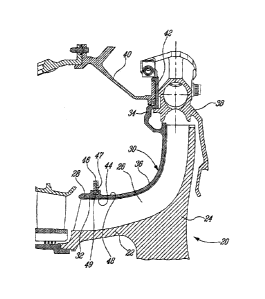
Figure 2 is an enlarged cross-sectional view of a compressor portion of the
gas turbine engine shown in Fig. 1.

DETAILED DESCRIPTION OF THE PREFERRED EMBODIMENTS

Fig.l illustrates a gas turbine engine 10 generally comprising in serial flow
communication a fan 12 through which ambient air is propelled, a multistage
compressor 14 for pressurizing the air, a combustor 16 in which the compressed
air is
mixed with fuel and ignited for generating an annular stream of hot combustion
gases, and a turbine section 18 for extracting energy from the combustion
gases.

As shown in Fig. 2, the compressor 14 comprises an impeller or compressor
rotor 20 including an inducer portion 22 and an exducer portion 24 mounted for
rotation about a central axis 11 (Fig. 1) of the engine 10. The compressor
rotor 20 has
a series of circumferentially distributed blades 26 extending radially
outwardly to tip
ends 28. The compressor rotor 20 is surrounded by a stationary annular
compressor
shroud 30. The compressor shroud 30 comprises an axially extending forward end
portion 32 and a radially extending aft end portion 34 integrally
interconnected by a
knee 36 defining a bend from axial to radial. The compressor shroud 30 is
cantilevered from the diffuser 38 and the rear case 40 of the engine via a
flange spigot
42 defined in the aft end portion 34 of the shroud 30.

The compressor shroud 30 has a radially inner surface 44 defining an outer
flow path boundary for the air flowing across the impeller 20. The radially
inner
-3-


CA 02638637 2008-08-13

surface 44 of the shroud 30 is disposed in close proximity to the tip ends 28
of the
blades 26 and defines therewith a tip clearance. In use, the rotation of the
compressor
rotor 20, the pressure variation in the air flowing across the compressor 14
and
mechanical sources can induce vibrations in the compressor shroud 30.
Excessive
vibration can cause fatigue or cracking of the structural member thereby
adversely
affecting the overall efficiency of the engine and its durability.

It is herein proposed to provide a mechanical damper at the forward end
portion 32 of the shroud 30 in order to minimize the effect of vibratory
stress and
improve durability. As shown in Fig. 2, this can be achieved by mounting a
ring 46 in
an annular channel 47 defined in a radially outwardly facing surface 48 of the
shroud
30. The ring 46 is self-supported in the channel 47, and is allowed to slip
therein. The
ring 46 is configured so as to be preloaded in frictional engagement on its
inside
diameter with the radially outwardly facing, circumferential surface 49 of the
channel
47 and at its axially facing sides with the axially spaced-apart sidewalls
bordering the
channel 47. The relative sliding movement between the ring 46 and the shroud
30
generates friction which contributes to dissipate the vibration in the shroud
30.

As shown in Fig. 2, additional friction and, thus, additional damping can be
provided through the use of a multi-turn spiral wound retaining ring of the
type
commonly used in order to fasten two concentric parts together. The adjacent
axially-
facing surfaces of the coils forming the multi-turn ring 46 provide additional
frictional surfaces which contribute to further dissipate the vibrations. In
this way,
the friction between 1) the inner diameter of the ring 46 and the outer
surface 49 of
the shroud 30, 2) the axially facing end surfaces of the ring 46 and the
adjacent
axially facing sidewalls of channel 47 and 3) adjacent surfaces of the coils
of the ring
46, all together contribute to dampen the vibrations induced in the shroud 30.

It is understood that multiple adjacent single-turn rings could be used as an
equivalent to the illustrated multi-turn ring.

The WS, WSM, DNS, ES, WST and WSW retaining ring series
manufactured by Smalley Steel Ring Company could for instance be used as
damping
rings. Other suitable retaining ring could be used as well.

-4-


CA 02638637 2008-08-13

Retaining rings having relatively high stiffness in the radial direction due
to
their narrow and tall cross-section (see Fig. 2) shall not deflect with the
shroud,
thereby creating relative motion (slip) between the shroud 30 and the
retaining ring
47 which, in turn, results in energy absorption and damping. As shown in Fig.
2, this
can be achieved with a multi-turn ring having simple rectangular cross-
sectional coils
with a plain inner circumferential surface seating on a correspondingly plain
outer
surface 49 of channel 47 on the shroud 30. The cross-section of the ring 46
can be
adjusted to provide the relative stiffness with the shroud to maximize
relative motion
and, thus, the damping of the induced vibration.

The slip may be both radial and tangential at the inside diameter and
adjacent axial faces of the channel 47 with any displacement causing slip
between the
ring 46 and shroud 30 as well as each of the coils of the retaining ring 46
due to its
multi- turn design. It has been demonstrated that more turns of the ring
significantly
increases the damping by providing additional frictional surfaces as each coil
slips
relative to each other in addition to the slip occurring on the shroud
contacting
surfaces.

In view of the foregoing, it is apparent that the mechanical damper
contributes to improve the durability of the shroud 30 with minimum effect on
the
engine configuration. Furthermore, the use of a retaining ring as a mechanical
damper
provides a simple, reliable and relatively inexpensive way of damping the
vibration
induced in the shroud 30. It is also easy to implement, maintain and
manufacture.

The above description is meant to be exemplary only, and one skilled in the
art will recognize that changes may be made to the embodiments described
without
departing from the scope of the invention disclosed. For example, while the
present
invention has been described in the context of an impeller shroud, it is
understood
that a similar concept could be used on other engine static parts prone to
vibrations,
such as rotor shrouds in general, stators and baffles. The damping ring in
some
instances could also be mounted to an internal surface of the part to be
dampened as
opposed to the illustrated external mounting. Still other modifications which
fall
within the scope of the present invention will be apparent to those skilled in
the art,

-5-


CA 02638637 2008-08-13

in light of a review of this disclosure, and such modifications are intended
to fall
within the appended claims.

-6-

Representative Drawing
A single figure which represents the drawing illustrating the invention.
Administrative Status

For a clearer understanding of the status of the application/patent presented on this page, the site Disclaimer , as well as the definitions for Patent , Administrative Status , Maintenance Fee  and Payment History  should be consulted.

Administrative Status

Title Date
Forecasted Issue Date 2016-06-28
(22) Filed 2008-08-13
(41) Open to Public Inspection 2009-05-27
Examination Requested 2013-07-17
(45) Issued 2016-06-28

Abandonment History

There is no abandonment history.

Maintenance Fee

Last Payment of $473.65 was received on 2023-07-21


 Upcoming maintenance fee amounts

Description Date Amount
Next Payment if standard fee 2024-08-13 $624.00
Next Payment if small entity fee 2024-08-13 $253.00

Note : If the full payment has not been received on or before the date indicated, a further fee may be required which may be one of the following

  • the reinstatement fee;
  • the late payment fee; or
  • additional fee to reverse deemed expiry.

Patent fees are adjusted on the 1st of January every year. The amounts above are the current amounts if received by December 31 of the current year.
Please refer to the CIPO Patent Fees web page to see all current fee amounts.

Payment History

Fee Type Anniversary Year Due Date Amount Paid Paid Date
Application Fee $400.00 2008-08-13
Maintenance Fee - Application - New Act 2 2010-08-13 $100.00 2010-08-13
Maintenance Fee - Application - New Act 3 2011-08-15 $100.00 2011-07-05
Maintenance Fee - Application - New Act 4 2012-08-13 $100.00 2012-08-13
Request for Examination $800.00 2013-07-17
Maintenance Fee - Application - New Act 5 2013-08-13 $200.00 2013-08-13
Maintenance Fee - Application - New Act 6 2014-08-13 $200.00 2014-06-16
Maintenance Fee - Application - New Act 7 2015-08-13 $200.00 2015-07-06
Final Fee $300.00 2016-04-14
Maintenance Fee - Patent - New Act 8 2016-08-15 $200.00 2016-07-21
Maintenance Fee - Patent - New Act 9 2017-08-14 $200.00 2017-07-20
Maintenance Fee - Patent - New Act 10 2018-08-13 $250.00 2018-07-19
Maintenance Fee - Patent - New Act 11 2019-08-13 $250.00 2019-07-22
Maintenance Fee - Patent - New Act 12 2020-08-13 $250.00 2020-07-21
Maintenance Fee - Patent - New Act 13 2021-08-13 $255.00 2021-07-21
Maintenance Fee - Patent - New Act 14 2022-08-15 $254.49 2022-07-21
Maintenance Fee - Patent - New Act 15 2023-08-14 $473.65 2023-07-21
Owners on Record

Note: Records showing the ownership history in alphabetical order.

Current Owners on Record
PRATT & WHITNEY CANADA CORP.
Past Owners on Record
ABATE, ALDO
BONNIERE, PHILIPPE
ELEFTHERIOU, ANDREAS
THERATIL, IGNATIUS
Past Owners that do not appear in the "Owners on Record" listing will appear in other documentation within the application.
Documents

To view selected files, please enter reCAPTCHA code :


To view images, click a link in the Document Description column. To download the documents, select one or more checkboxes in the first column and then click the "Download Selected in PDF format (Zip Archive)" or the "Download Selected as Single PDF" button.

List of published and non-published patent-specific documents on the CPD .

If you have any difficulty accessing content, you can call the Client Service Centre at 1-866-997-1936 or send them an e-mail at CIPO Client Service Centre.


Document
Description 
Date
(yyyy-mm-dd) 
Number of pages   Size of Image (KB) 
Cover Page 2009-05-21 1 43
Abstract 2008-08-13 1 6
Description 2008-08-13 6 273
Claims 2008-08-13 4 160
Drawings 2008-08-13 2 40
Representative Drawing 2009-05-05 1 17
Claims 2015-08-14 3 149
Representative Drawing 2016-05-03 1 14
Cover Page 2016-05-03 1 39
Assignment 2008-08-13 5 150
Prosecution-Amendment 2013-07-17 2 71
Prosecution-Amendment 2015-02-17 3 242
Amendment 2015-08-14 6 266
Final Fee 2016-04-14 2 68