Note: Descriptions are shown in the official language in which they were submitted.
CA 02638712 2015-01-14
SELF-ADJUSTING WRENCH
BACKGROUND OF THE INVENTION
Field of the Invention
[ 0001] The present invention pertains to wrenches, and more
particularly to a self-adjusting wrench.
Discussion of Related Art
(0002j Various wrenches are known. Some wrenches are closed-end
wrenches, that is wrenches that encompass the circumference of a workpicce.
In some circumstances, due to tight working quarters for example, use of a
closed-end wrench to drive a workpiece may be precluded. As an alternative
to a closed-end wrench, an open-ended wrench may be used.
100031 While some designs for open-ended wrenches are available,
these designs have some limitations.
[0004] FIGURE 1 is an elevational view of a conventional open-end
wrench. As shown in Figure I, conventional open-end wrench 10 has a handle
11 and two containing parts 12 on both sides of handle 11. Each containing
part 12 has a containing groove 13 for receiving a nut-locking component 20,
and two jaws 14, one jaw 14 on each side of containing groove 13.
100051 When operated, open-end wrench I 0 can be applied to nut-
locking component 20. The containing groove 13 engages external surface of
the nut-locking component 20 such that the two opposite containing surfaces
141 between the two jaws 14 are brought in contact with two symmetrical
outer surfaces 21 of the nut-locking component 20. By applying a torque to
the handle 11 of the wrench 10 to rotate the wrench 10, the nut-locking
1
component 20 will rotate accordingly. Although the open-end wrench 10
provides the function of rotating the nut-locking component 20, it has the
following deficiencies.
CA 02638712 2015-01-14
[00061 Because the working space to complete a full rotation 3600 of
the wrench 10 may be limited, the nut-locking component 20 may not
complete a full rotation. Hence, after open-end wrench 10 rotates nut-locking
component 20 to an intended position in one direction, the wrench 10 has to be
removed from the nut-locking component 20 and rotated in the opposite -
direction in order to continue rotating nut-locking component 20 in the
initial
direction. Because the two jaws 14 are fixed, the open-end wrench 10 should
be disconnected from nut-locking component 20 before rotating the wrench 10
in the opposite direction so as not to drive nut-locking component 20 to
rotate
in the opposite direction. Once the jaws 14 are brought again in contact
against the two opposite surfaces 21, the rotation of nut-locking component 20
can be resumed. Therefore, the wrench 10 can be inconvenient to use.
[0007] Furthermore, when the open-end wrench 10 is applied to the
nut-locking component 20, the two symmetrical outer surfaces 21 of nut-
locking component 20 are held between the two parallel containing surfaces
141 in the containing groove 13 of the open-end wrench 10. Therefore, when
the wrench is applied to the nut-locking component 20 whose size (a distance
between the two opposite surfaces 21) is smaller than a distance between the
two parallel containing surfaces 141. each of the two containing surfaces 141
forms an angle relative to each of the two surfaces 21 of nut-locking
component 20. When a torque is exerted on open-end wrench 10 to rotate nut-
locking component 20, the nut-locking component 20 can sometimes be
stripped.
BRIEF SUMMARY OF THE INVENTION
[0008] An aspect of the present invention is to provide an open-end
wrench including a handle portion and a containing portion. The containing
portion includes a first jaw and a second jaw. The jaws define a containing
groove configured to receive a workpiece. The open-end wrench also includes
a chuck base, a resilient member and a stop protector. The chuck base is
slidably mounted on the second jaw. The resilient member is operatively
disposed between the second jaw and the chuck base. The resilient member is
configured to bias the chuck base towards the handle. The protector stop
2
CA 02638712 2015-01-14
interacts between the second jaw and the chuck base to limit the extent of
relative movement therebetween to limit the extent of compression of the
resilient member.
BRIEF DESCRIPTION OF THE DRAWINGS
100091 in the accompanying drawings:
100101 FIGURE 1 is an devotional view of a conventional open-end
wrench, in accordance with the prior art;
100111 FIGURE 2 is an exploded perspective view of a wrench,
according to an embodiment of the present invention;
[0012] - FIGURE 3 is a combined devotional view and broken away
section view showing a condition when the wrench drives a nut-locking
component to rotate and become tightened, according to an embodiment of the
present invention;
100131 FIGURE 4 is a combined elevati.onal view and broken away
view showing a condition of idle running of the wrench depicted in FIGURE
3;
100141 FIGURE 5 is a combined devotional view and broken away
view showing a condition when the wrench shown in FIGURE 3 is applied to
a nut-locking component of a smaller size;
[00151 FIGURE 6 is an exploded perspective view of a wrench,
according to another embodiment of the present invention;
100161 FIGURES 7A, 713 and 7C show the various phases of operation
of the wrench depicted in FIGURE 6; and
(0017) FIGURE g is an elevational view of a portion of the wrench
depicted in FIGURE 6 showing dimensions of features of the wrench depicted
in FIGURES 6 and 7A-7C.
3
CA 02638712 2015-01-14
DETAILED DESCRIPTION OF SEVERAL EMBODIMENTS OF THE
INVENTION
[00181 FIGURE 2 is an exploded perspective view of an open-end
wrench 3, according to an embodiment of the present invention and FIGURE
3 is a combined elevational view and broken away sectional view of the open-
end wrench 3. Open-end wrench 3 comprises a handle 30, a containing part
40, a chuck base 50, a dowel pin 60 and a resilient member 70.
[00191 The containing part 40 can be provided on one side of the
handle 30 or on both sides of the handle 30. As used herein, the term
containing part refers broadly to the open-ended region of an open ended
wrench that receives a fastener or nut. In one embodiment, the containing part
40 includes containing groove 42 having an outer surface 41 which contacts
handle 30. The containing groove 42 is configured to receive nut-locking
component 80. The containing part 40 also includes a first jaw 43 and a
second jaw 44 on opposite sides of containing groove 42. A sliding groove 45
is provided in the second jaw 44 along a first direction X. The sliding groove
45 communicates with containing groove 42 and outer surface 41. The
containing part 40 further includes an opening 46 provided on the second jaw
44 along a second direction Y perpendicular to the first direction X. The
opening 46 communicates with sliding groove 45.
[00201 The first jaw 43 has a first pressing surface 431 and the second
jaw 44 has a second pressing surface 441. The first pressing surface 431 of
the
first jaw 43 and the second pressing surface 441 of the second jaw 44 are
slanted relative to each other, i.e., not parallel to each other. In addition,
the
containing part 40 has also a third pressing surface 47 and a fourth pressing
surface 48. The third pressing surface 47 and the fourth pressing surface 48
intersect and extend, respectively, from the first pressing surface 431 and
the
second pressing surface 441 towards the handle 30.
100211 The chuck or chuck base 50 is configured to be slidably
mounted in sliding groove 45 of the second jaw 44. As used herein, the term
4
CA 02638712 2015-01-14
"chuck" or "chuck base" are used synonymously and refers broadly to a
movable part mounted on a jaw that can engage a nut or fastener to drive the
nut or fastener. The chuck base 50 includes a sliding block 51 configured to
be mounted inside sliding groove 45. The sliding block 51 is movable inside
= sliding groove 45 along the first direction X. The sliding block 51 has
an
elongated aperture 53 along the first direction X. The elongated aperture 53
has an internal surface 54.
100221 The chuck base 50 also includes a clamp splice 52
configured
to be mounted to inner surface 511 of sliding block 51 which faces containing
groove 42. The clamp splice 52 has a backstop surface 521, one side of which
is opposite to inner SUrfaCC 511. The clamp splice 52 extends away from the
top and bottom edges of inner surface 511. The clamp splice 52 has a
containing part 522 with a bumped shape oriented towards groove 42. In this
embodiment, the clamp splice 52 is fixed to sliding block 51. Alternatively,
the clamp splice 52 can be configured to move along the inner surface 511 of
sliding block 51.
[00231 When the sliding block 51 of chuck base 50 is mounted
inside
the sliding groove 45 of the second jaw 44, the elongated aperture 53 can be
aligned with the opening 46 in the second jaw 44. The dowel pin 60 can then
be inserted into the opening 46 and elongated aperture 53, along the second
direction Y. As a result, the sliding block 51 can slide back and forth inside
the sliding groove 45 guided by the dowel pin 60 and the backstop surface 521
of clamp splice 52 which comes in contact with second pressing surface 441
of the second jaw 44, while being prevented from leaving the slide groove 45.
100241 In this embodiment, the resilient member 70 is a
spring.
However, any other suitable resilient member can be used, such as an elastic
material. The resilient member 70 is disposed in elongated aperture 53. An
extremity 71 of the resilient member 70 is brought in contact with the dowel
pin 60 and an opposite extremity 72 of the resilient member 70 is brought in
contact with surface 54 of the elongated aperture 53. As a result, the
resilient
member 70 can exert a -force on the sliding block 51 of chuck base 50 to bias
the chuck base 50 towards the handle 30.
CA 02638712 2015-01-14
[00251 in operation, the open-end wrench 3 is applied to a nut-locking
component 80, as depicted in FIGURE 3, by aiming containing groove 42 of
containing part 40 at nut-locking component 80 so as to position the nut-
locking component 80 inside containing groove 42. Two symmetrical outer
surfaces 81 and 82 of nut-locking component 80 are held by and positioned
between the first pressing surface 431 of the first jaw 43 and containing part
522 of clamp splice 52, respectively. At the same time, outer surface 83 of
nut-locking component 80 is also brought in contact with the third pressing
surface 47 of containing part 40. When a clockwise torque is exerted on
handle 30, nut-locking component 80 is driven to rotate clockwise, for
example to tighten the nut-locking component, as illustrated by the arrows in
FIGURE 3.
100261 FIGURE 4 is a combined devotional view and broken away
view showing the wrench depicted in FIGURE 3 when rotated counter-
clockwise and running idle. As shown in FIGURE 4, when a counter-
clockwise torque is exerted on handle 30, initially the clamp splice 52 of
chuck base 50 will be driven by nut-locking component 80 and the chuck base
50 will be moved away from handle 30 along the first direction X. The two
symmetrical outer surfaces 81 and 82 of nut-locking component 80 will no
longer be held by and positioned between the first pressing surface 431 of the
first jaw 43 and the containing part 522 of clamp splice 52. When the chuck
base 50 moves away from the handle 30 along the first direction X. the dowel
pin 60 being fixed and held in opening 46, the resilient member 70 is
compressed between the dowel pin 60 and the surface 54 of the elongated
aperture 53, as depicted in FIGURE 4. In this case, the open-end wrench 3 is
running idle in that it does not drive nut-locking component 80 to rotate
counter-clockwise. It is noted that the clamp splice 52 also moves along with
the chuck base 50.
100271 When another counter-clockwise torque is exerted on the
handle 30, the handle will drive nut-locking component 80 to rotate slightly,
and drive outer surface 81 of nut-looking component 80 to press against the
first pressing surface 431 of the first jaw 43. Thereafter, the resilient
member
6
CA 02638712 2015-01-14
70 will drive chuck base 50 to move towards handle 30 along the first
direction X. The two symmetrical outer surfaces 81 and 82 of nut-locking
component 80 are held by and positioned between the first pressing surthee
431 of the first jaw 43 and containing part 522 of clamp splice 52. When a
clockwise torque is exerted on handle 30. nut-locking component 80 is driven
to rotate clockwise. Thus, nut-locking component 80 can be further tightened.
[0028] FIGURE 5 is a combined elevational view and broken away
view showing a condition when the wrench shown in FIGURE 3 is applied to
a nut-locking component of a smaller size. As shown in FIGURES 3 and 5,
the first pressing surface 431 of the first jaw 43 is working together with
containing part 522 of clamp splice 52 to hold the two symmetrical outer
surfaces 91 and 92 of nut-locking component 90. The first pressing surface
431 and the second pressing surface 441 of the second jaw 44 are slanted and
not parallel to each other. Therefore, when the open-end wrench is applied on
a nut-locking component 90 of a smaller size, the two symmetrical outer
surfaces 91 and 92 of nut-locking component 90 can be held partially by and
positioned between the first pressing surface 431 and containing part 522. As
a
result, the nut-locking component 90 can be further tightened without
damaging the nut-locking component 90. Therefore, the open-end wrench 3
can be configured to quickly engage and position workpieces of various sizes.
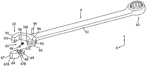
[00291 FIGURE 6 is an exploded perspective view of an open-end
. wrench 6, according to another embodiment of the present invention. Open-
end wrench 6 is similar in many aspects to the open-end wrench 3. Open-end
wrench 6 comprises a handle 61, an open containing part 62, a closed
containing part 63, a chuck base or pawl 64, a dowel pin 66, a resilient
member 98, and in this embodiment, a spring protector stop 99 (in the form of
a pin in this embodiment).
[00301 Although the open containing part 62 is shown in FIGURE 6
on one side of the handle 61, another open containing part 62 can be provided
on an opposite side of the handle 61 instead of the closed containing part 63.
The containing part 62 includes containing groove or slot 65. The containing
groove 65 is configured to receive nut-locking component 100 (shown in
7
CA 02638712 2015-01-14
FIGURES 7A-7C). In this embodiment, a back surface of containing groove
65 has a curved configuration. The containing part 62 also includes a first
jaw
93 and a second jaw 94 on opposite sides of containing groove 65. A sliding
groove 95 is provided in the second jaw 94 along a first direction X. As seen
in FIGURE 6, the sliding groove 95 communicates with containing groove 65.
The containing part 62 further includes an opening 96 provided on the second
jaw 94 along a second direction Y perpendicular to the .first direction X. The
opening 96 communicates with sliding groove 95.
[00311 The first jaw 93 has a first pressing surface 193 and the second
jaw 94 has a second pressing surface 194. The first pressing surface 193 of
the first jaw 93 and the second pressing surface 194 of the second jaw 94 are
slanted relative to each other in the first direction X. i.e., not parallel to
each
other in the first direction X.
100321 Similar to the previously described embodiment, the chuck
base 64 is configured to be slidably mounted in sliding groove 95 of the
second jaw 94. The chuck base 64 includes a sliding block 67 configured to
be mounted inside sliding groove 95. The sliding block 67 is movable inside
sliding groove 95 along the first direction X. The sliding block 67 has a
thick
upper portion 67A and a thin flat lower portion 6713 disposed generally
centrally below the thick portion 67A and extending downwardly and
rearwardly relative to thick portion 67A. The transitioning surfiice extending
laterally from the thick portion 67A to the thin flat portion 6713 form an
edge
portion or edge surface 67C. The edge surface 67C generally faces
downwardly and is an under surface of thick portion 67A that engages the
upward facing second pressing surface 194 of the second jaw 94. The thin flat
portion 6713 is configured to slide inside sliding groove 95. The sliding
block
67 has also a ramped surface 671) (shown in FIGURES 7A-7C). The ramped
surface 671) has a ramp portion 67E and surface portions 67F and 67G. The
ramp portion 67E is angled relative to the two surfaces 67F and 67G. When
the chuck base 64 is mounted in sliding groove 95, the edge 67C of the sliding
block 67 abuts and slides against the second pressing surface 194 of the
second jaw 94. In addition, the sliding block 67 has an elongated aperture 68
8
CA 02638712 2015-01-14
along the first direction X provided in the thin flat portion 67B. The
elongated
aperture 68 has an internal surface 69.
100331 Similar to the previous embodiment, when the sliding block 67
of chuck base 64 is mounted inside the sliding groove 95 of the second jaw 94,
the elongated aperture 68 can be aligned with the opening 96 in the second jaw
94. The dowel pin 66 can then be inserted through the opening 96 and through
the elongated aperture 68, along the second direction Y. As a result, the
sliding block 67 can slide back and forth inside the sliding groove 95 guided
by the dowel pin 66 and the edge 67C of the sliding block. 67 while being
prevented from leaving the sliding groove 95.
100341 FIGURES 7A-7C are cross-sectional views of the open-end
wrench 6 showing various phases of operation of the open-end wrench 6
F
depicted in FIGURE 6 and the relative positioning of the resilient member 98
and protection pin 99 during the operation of wrench 6. The resilient member
98 is disposed in the elongated aperture 68. In this embodiment, the resilient
member 98 is a spring. However, any other suitable resilient member can be
used, such as an elastic or compressible material. An extremity 98A of the
resilient member 98 is brought in contact with the dowel pin 66 and an
opposite extremity 98B of the resilient member 98 is brought in contact with
internal surface 69 of the elongated aperture 68. In this way, the resilient
member 98 can exert a force on the sliding block 67 of chuck base 64 to bias
the sliding block 67 towards the handle 30. The protection pin 99 is disposed
to protect the resilient member 98. In one embodiment, the protection pin or
protector stop 99 is disposed inside the resilient member (e.g., a spring) 98.
For example, the protection pin 99 can be a cylindrical piece of metal that
can
be inserted in the core of the spring 98. In one embodiment, the protection
pin
99 may optionally be provided with a head portion at one end of the
cylindrical piece of metal. A diameter of the head portion can be sized to be
larger than a diameter of the spring 98 so that the head is positioned outside
the spring confines, and the protection pin 99 can move with the compression
and elongation of the spring 98. In one embodiment (e.g., where the protector
stop comprises the pin 99 within the spring), during compression of the spring
9
CA 02638712 2015-01-14
98, the protection pin 99 can also prevent bending and/or distortion of the
spring 98. The protection pin 99 can also be selected to limit compression of
the resilient member 98. That is, because the protective stop or pin 99 is
disposed between the dowel pin 66 and the opposing end surface 69 of groove
68 (for example, the head of the pin 99 facing the pin 99), the length of pin
99
is sandwiched between pin 66 and surface 69 to limit the extent of
compression of the spring 98.
[00353 Although in this embodiment the stop 99 takes the form of a
pin within spring 98, it is contemplated that a different structure that
limits the
extent of movement of sliding block 67 to protect excessive compression of
spring 98. For example, stopping edges can be provided on the flat surface
6713 and on an opposing surface of the second jaw 94 inside the sliding groove
' 95, which when brought in contact, stop the movement of the sliding block 67
to thus limit the compression of the spring 98.
[00361 In operation, the open-end wrench 3 is applied to a nut-locking
component 100, as depicted in FIGURE 7A, by directing containing groove 65
of containing part 62 towards nut-locking component 100 so as to position the
nut-locking component 100 inside containing groove 65. Two symmetrical
outer surfaces 101 and 102 of nut-locking component 100 are held by and
positioned between the first pressing surface 193 of the first jaw 93 and the
surface portion 67F of ramped surface 67D in sliding block 67 of the chuck
base 64, respectively. When a clockwise torque is exerted on handle 61, nut-
locking component 100 is driven to rotate clockwise, for example to tighten
the nut-locking component 100, as illustrated by the arrow in FIGURE '7A.
For example, in the case where the nut-locking component 100 is a nut having
a hexagonal head (as shown in FIGURES 7A-7C), one side 103 of the
1
hexagonal head of the nut-locking component 100 makes an angle of about
60 with the surface portion 67F of ramped surface 671) of the sliding block
67 (as shown in FIGURE 7A).
100371 As shown in FIGURE 713, when a counter-clockwise torque is
exerted on handle 61, initially the sliding block 67 of chuck base 64 will be
driven by nut-locking component 100 and the sliding block 67 of the chuck
CA 02638712 2015-01-14
base 64 will be moved away from handle 61 along the first direction X. The
two symmetrical opposite outer surfaces 101 and 102 of nut-locking
component 100 will no longer be held and positioned between the first
pressing surface 193 of the first jaw 93 and the surface portion 67F in
sliding
block 67. A portion of the surface 102 of the nut-locking component 100
contacts the ramp portion 67E which is angled with respect to the surface
portion 67F of ramped surface 671). In one embodiment, the angle between
the surface portion 67F and the ramp portion 67E is approximately 210'.
When the sliding block 67 moves away from the handle 61 along the first
direction X, with the dowel pin 66 being fixed and held by the second jaw 94
inside opening 96, the resilient member 98 is compressed between the dowel
pin 66 and the surface 69 of the elongated aperture 68. As described in the
above paragraphs, the resilient member 98 is only compressed to a certain
extent, as the protection pin 99 disposed inside the resilient member 98 will
act as a stop to limit the extent of travel. In one embodiment, the protection
pin 99 can also guide the resilient member 98 during its compression, thus
preventing bending and/or distortion of the resilient member 98.
100381 During the counter-rotation phase, the open-end wrench 6 runs
idle in that the movement of sliding block 67 allows the component 100 to slip
within the groove 65 so that wrench 6 does not drive nut-locking component
100 to rotate counter-clockwise. In the case where the nut-locking component
100 is a nut having a hexagonal head (as shown in FIGURES 7A-7C), the side
103 of the hexagonal head of the nut-locking component 100 now makes an
angle of about 90 with the Surface portion 67F of ramped surface 671) of the
sliding block 67 (as shown in FIGURE 7B).
[00391 As shown in FIGURE 7C, when another clockwise torque is
exerted on the handle 61, surface 101' of nut-locking component 100 adjacent
to surface 101 is brought in contact with the first pressing surface 193 of
the
first jaw 93 and surface 102' of nut-locking component 100 adjacent to surface
102 is brought in contact with surface portion 67F of ramped surface 671) of
the sliding block 67. The resilient member 98 will drive chuck base 64 to
move towards handle 61 along the first direction X. When a clockwise torque
11
CA 02638712 2015-01-14
is exerted on handle 61, nut-locking component 100 is driven to rotate
clockwise. Thus, nut-locking component 100 can be further tightened.
100401 FIGURE 8 is an elevational view of the open-end wrench 6
depicted in FIGURES 6 and 7A-7C showing dimensions of some features of
the wrench 6. As shown in FIGURE 8, the first pressing surface 193 has a
first surface portion 193A and a second surface portion 19313. The first
surface portion 193A and the second surface portion 193B are slightly angled
relative to each other. The first surface portion 193A is parallel to surface
portion 67F of ramped surface 67D. The first surface 193A of the first
pressing surface 193 contacts the surface 101 of the nut-locking component
100 at contact area 200. The contact area 200 between the surface 101 and the
surface portion 193A is shown in FIGURE 8 as a bold line. The surface
portion 67F of ramped surface 671) of the sliding block 67 contacts the
surface
102 of the nut-locking component 100 at contact area 202. The contact area
202 between the surface 102 and the surface portion 67F of the ramped
surface 67D is shown in FIGURE 8 as a bold line. The contact area 202 is
substantially parallel to the contact area 200.
[0041] It must be appreciated from the above paragraphs that in one
embodiment, the first jaw 93 has a rearward surface region 193A that is
parallel to a first workpiece engaging surface 67F of the slidable chuck 64.
The first jaw 93 has a forward surface region 1 93B that extends away from the
workpiece engaging surface 67F as it extends away from the rearward surface
region 193A. A second workpiece engaging surface 6713 of the slidable chuck
64 ramps downwardly as it extends rearwardly from the first workpiece
engaging surface 67F.
100421 The containing groove 65 of the open-end wrench 6 has a depth
13 defined as a distance between an edge 204 of the second jaw 94 and a
contact point (or contact line) 206 between the nut-locking component 100
and an interior surface of the containing groove 65. The depth B is greater
than a distance A between an extremity 208 of the nut-locking component 100
within contact area 202 and the contact point (or contact line) 206. By
configuring the containing groove 65 such that the depth B is greater than the
12
CA 02638712 2015-01-14
distance A, the chuck base 64 can be prevented from being pushed out away
from the second jaw 94 when operating the wrench 6 (for example, during
tightening, i.e. clockwise rotation, of the nut-locking component 100).
100431 Furthermore, in this configuration, a distance L between an
edge 200A in contact area 200 and an edge 202A in contact area 202 is greater
than a distance S between the surface 101 and the opposite surface 102 of the
nut-locking component 100. In this configuration, the nut-locking component
100 is engaged and potential slip of the nut-locking mechanism can be
prevented when driving the nut-locking component 100 in the clockwise
direction.
100441 It must also be appreciated that one of the advantages of the
protector stop 99 is that the protector stop 99 can also be used in a device
with
a movable jaw, as disclosed in U.S. Patent Application No. 12/027,103.
hereby incorporated by reference in its entirety.
1.00451 Although the open-end wrenches 3 and 6 are depicted herein as
operating a nut-locking component. 80, 100 having a hexagonal-shaped head,
the wrenches 3 and 6 can be used to operate other nut-locking components.
For example, the wrenches 3 and 6 can be used to operate a nut or bolt having
a polygonal head, such as, a square head, an octagonal head, etc. The many
features of the present invention are apparent from the detailed specification
and thus, it is intended by the appended claims to cover all such features of
the
described open-end wrench which follow the true spirit and scope of the
invention.
10040 It should be appreciated that in one embodiment, the drawings
herein are drawn to scale (e.g., in correct proportion). However, it should
also
be appreciated that other proportions of parts may be employed in other
embodiments.
13