Note: Descriptions are shown in the official language in which they were submitted.
CA 02638718 2008-08-13
MODULAR FUEL NOZZLE AIR SWIRLER
TECHNICAL FIELD
The technical field of the invention relates generally to gas turbine engines
and, more particularly, to a fuel nozzle air swirler for use in gas turbine
engines.
BACKGROUND OF THE ART
Fuel nozzles are used to deliver a fuel/air mixture to combustors of gas
turbine engines. The discharge end of such fuel nozzles and especially the air
swirler
thereof is exposed to elevated temperatures and to the harsh environment
inside the
combustor, and, is therefore subject to fretting and oxidation damage.
Conventionally, once the damage on the air swirler of the fuel nozzle becomes
too
severe, the entire nozzle must be replaced. Due to the geometric configuration
of the
nozzles and the materials that are typically used for such nozzles, the
manufacturing
costs associated with producing these fuel nozzle can be relatively high.
Accordingly, there is a need to provide a solution for reducing the costs
associated with replacing damaged fuel nozzles that are used in gas turbine
engines.
SUMMARY
It is therefore an object of the present invention to provide a fuel nozzle
air
swirler that addresses the above-mentioned concerns.
According to one broad aspect there is provided a modular fuel nozzle air
swirler for a gas turbine engine, the nozzle comprising: a body defining a
fuel
passage extending between an inlet end and a discharge end of the body, the
discharge end having a peripheral end surface, the body having at least one
first
interlocking member; and an annular cap having a shoulder surface interfacing
with
the peripheral end surface of the body, the annular cap having at least one
second
interlocking member cooperating with the at least one first interlocking
member, the
peripheral end surface of the body and the shoulder surface defining a
plurality of
through air channels.
-1-
CA 02638718 2008-08-13
According to another aspect, there is provided a fuel nozzle air swirler for a
gas turbine engine, the nozzle comprising: a body having a central fuel
passage
extending therethrough and exiting the body through a spray orifice; and an
annular
cap positively secured to the body via cooperating securing means provided on
the
cap and body, the annular cap circumscribing the spray orifice, a plurality of
through
air channels being defined at an interface between the body and the annular
cap and
extending towards the central fuel passage.
According to a further aspect, there is provided a fuel nozzle air swirler
assembly for use in a gas turbine engine, the assembly comprising: a body
defining a
central fuel passage extending between an inlet end and a discharge end of the
body,
the discharge end having a peripheral end surface, the peripheral end surface
having a
plurality of circumferentially spaced through slots extending substantially
radially
about the central fuel passage; and an annular cap having a shoulder surface
for
interfacing with the peripheral end surface of the body and cooperating with
the slots
to define through air channels, the cap being positively secured to the body
via a
latching mechanism provided on the cap and body.
Further details of these and other aspects of the present invention will be
apparent from the detailed description and figures included below.
DESCRIPTION OF THE DRAWINGS
Reference is now made to the accompanying figures, in which:
Figure 1 is a schematic axial cross-section view of a gas turbine engine;
Figure 2 is an axial cross-section view of a fuel nozzle air swirler according
to one embodiment of the present invention;
Figure 3 is an isometric rear view of the fuel nozzle air swirler of Figure 2;
and
Figure 4 is an isometric rear view of the fuel nozzle air swirler of Figure 2
in
a disassembled state.
-2-
CA 02638718 2008-08-13
DETAILED DESCRIPTION OF THE PREFERRED EMBODIMENTS
Fig.l illustrates a gas turbine engine 10 of a type preferably provided for
use
in subsonic flight, generally comprising in serial flow communication a fan 12
through which ambient air is propelled, a multistage compressor 14 for
pressurizing
the air, a combustor 16 in which the compressed air is mixed with fuel and
ignited for
generating an annular stream of hot combustion gases, and a turbine section 18
for
extracting energy from the combustion gases. The fuel is supplied to the
combustor
16 via fuel nozzles whereby it is also mixed with the compressed air flowing
through
the air swirlers of the fuel nozzles. It will be understood however that the
invention is
equally applicable to other types of gas turbine engines such as a turbo-
shaft, a turbo-
prop, or auxiliary power units.
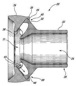
Referring now to Figs. 2-4, a fuel nozzle air swirler in accordance with one
embodiment of the present invention is generally shown at 20. The fuel nozzle
air
swirler comprises a body 22 defining a fuel passage generally shown at 24
extending
between an inlet end generally shown at 26 and a discharge end generally shown
at
28 (Fig. 4). The fuel passage 24 may be adapted to receive a fuel delivery
probe
connected to a fuel supply (both not shown). The distal end of the body 22 has
a
peripheral end surface 30 (shown in Fig. 4) surrounding a, spray orifice,
generally
shown at 31, of the fuel passage 24. The body 22 has a plurality of first
interlocking
members in the form of catches 32. The fuel nozzle air swirler 20 also
comprises an
annular cap 34 circumscribing the spray orifice 31. The cap 34 has a shoulder
surface
36 interfacing with the peripheral end surface 30 of the body 22. The annular
cap 34
has a plurality of second interlocking members in the form of latches 38
cooperating
with the catches 32.
The peripheral end surface 30 of the body 22 and the shoulder surface 36
define a plurality of through air channels generally shown at 40, at the
interface
between the annular cap 34 and the body 22. The channels 40 extend
substantially
radially about the spray orifice 31. The air channels 40 extend through the
fuel nozzle
air swirler 20 and are defined by circumferentially distributed through slots
41
extending across the peripheral end surface 30, and, the shoulder surface 36
of the
annular cap 34. The air channels 40 are use to deliver air into the combustor
16 and
-3-
CA 02638718 2008-08-13
also to interact with the fuel as it exits the spray orifice 31. The air
channels 40 may
be oriented to also comprise a tangential and/or axial component in relation
to the
central fuel passage 24 so as to promote atomisation of the fuel and/or induce
a
swirling motion of the air/fuel mixture as it enters the combustor 16.
Accordingly, the
term "substantially radially" mentioned above is intended to encompass
orientations
that have a radial component but that may not necessarily be purely radial.
The latches 38 are integrally formed with the cap 34 and comprise an arm
portion 42 and a protrusion 44 located at a distal end of the arm portion 42.
Each
protrusion 44 extends in a radially inward direction from the arm portion 42
and
defines an inside holding surface 46 identified in Figs. 2 and 4.
The cap 34 and the body 22 are manufactured as separate parts and are
subsequently assembled to form the nozzle air swirler 20. The latches 38
cooperate
with the catches 32 in order to positively secure the cap 34 to the body 22.
In order to
assemble the cap 34 to the body 22, the cap 34 may be assembled onto the
discharge
end 28 of the body 22 by inserting the latches 38 into the slots 41 and
bringing the
cap 34 and the body 22 together until the shoulder surface 36 comes in contact
with
the peripheral end surface 30, and then, turning the cap 34 relative to the
body 22 so
that the inside holding surfaces 46 of the latches 38 engage the catches 32 so
as to
prevent axial movement between the cap 34 and the body 22. This provides a
positive
securing arrangement of the cap 34 and the body 22. The slots 41 are
configured to
have a width that is greater than the width of the latches 38. In order to
provide
additional holding capacity between the cap 34 and the body 22, the cap 34 may
be
welded or brazed to the body 22. The weld (not shown) may be located at
location 48
and may comprise a spot weld between at least one of the latches 38 and at
least one
of the catches 32.
Alternatively, depending on the mechanical properties and the specific
configuration of the latches 38, the cap 34 may be assembled to the body 22 by
axially pressing the cap 34 against the discharge end 28 of the body 22 and
essentially
"snapping" the cap 34 to the body 22. Provided that the arm portions 42 of the
latches
38 are sufficiently resilient, as the cap 34 is pressed against the discharge
end 28 of
the body 22, the protrusions 44 slide against the peripheral end surface 30
and the
-4-
CA 02638718 2008-08-13
arm portions 42 resiliently bend outwardly until a radially outward portion of
the
peripheral end surface 30 is reached. The peripheral end surface 30 has a
frustro-
conical configuration which provides self-centering of the cap 34 and body 22.
Once
the protrusions 44 have slid passed the peripheral end surface 30, the arm
portions 42
return to their undeflected state and the inside holding surfaces 46 of the
protrusions
44 then engage the catches 32. Again, the cap 34 may further be welded or
brazed to
the body 22.
In use, it is typically an outlet end of fuel nozzles that suffers damage
caused
by the harsh environment inside the combustor 16. Advantageously, the modular
construction of the fuel nozzle air swirler 20 allows for the cap 34 to be
replaced
independently from the body 22. The cap 34 may be disassembled from the body
22
by reversing the assembling methods described above. In the case where the cap
34 is
welded to the body 22, the weld may be removed by grinding prior to
disassembly. If
the cap 34 cannot be disassembled from the body by reversing the above
assembling
methods because of excessive fretting damaged, corrosion or other reasons,
grinding
may again be used to destroy and/or break away the cap 34 from the body 22.
The
damaged cap 34 may then be disposed of and replaced by a new one while the
body
22 may be left in place and subsequently reused.
Both the cap 34 and the body 22 may be manufactured using metal injection
molding (MIM) techniques out of the same or different materials depending on
the
mechanical properties and high temperature properties that are desired for
each part.
The material for the cap 34 may be selected so as to more efficiently
withstand the
harsh environment in comparison with the body 22. Hence, a suitable but
cheaper
material may be selected for the body 22. In addition to material costs, a
person
skilled in the art will recognize that tooling costs may also be reduced by
producing
the cap 34 and the body 22 separately in comparison with a unitary nozzle. In
the
modular case, the body 22 does not have to be replaced as often as the cap 34
and
also simpler tooling is required for producing each part separately. For
example,
forming the slots 41 on the body 22 as opposed to through channels in a
unitary
nozzle significantly reduces the complexity of the moulds required for MIM.
-5-
CA 02638718 2008-08-13
Even though the latching mechanism shown in the figures comprises latches
38 and catches 32, one skilled in the art would recognize that other types of
securing
or latching mechanisms may also be used. A function of the interlocking
members is
to provide a positive interlocking arrangement between the cap 34 and the body
22
which prevents the cap 34 from being released in the combustor 16. Another
suitable
latching mechanism could include, for example, straight tangs provided on the
cap 34
fhat extend towards the body 22 and are bent over the catches 32. Again, the
tangs
could also be spot welded or brazed to the body 22.
In addition, it is apparent that in some instances the type of interlocking
members could be interchanged between the cap 34 and the body 22. For example,
some or all of the latches 38 could be disposed on the body 22 instead of the
cap 34
and the corresponding catches 32 could be disposed on the cap 34 instead of
the body
22. Further, the number of latches 38 and corresponding catches 32 could also
differ
from what is shown in the figures. For example, a single annular catch could
be
provided on the cap 34 while one or more cooperating latches would be provided
on
the body 32. Other variations in the type and specific locations of
interlocking
members are also possible.
The above description is meant to be exemplary only, and one skilled in the
art will recognize that changes may be made to the embodiments described
without
departing from the scope of the invention disclosed. For example, it is
apparent that
the present modular nozzle configuration could be applied to simplex or duplex
air-
assisted nozzles. Still other modifications which fall within the scope of the
present
invention will be apparent to those skilled in the art, in light of a review
of this
disclosure, and such modifications are intended to fall within the appended
claims.
-6-