Note: Descriptions are shown in the official language in which they were submitted.
CA 02639067 2008-08-22
MOTOR DRIVE ARCHITECTURE WITH ACTIVE SNUBBER
TECHNICAL FIELD
[0001] The description relates generally to electric
motors and, more particularly, to the control of electric
motors.
BACKGROUND
[0002] In control of electric machines such as permanent
magnet motors, current pulses due to electrical transients
may be flowed back to the power supply by the use of a
transient suppression feedback diode. When the power supply
is at some distance away from the motor control circuitry,
current pulses flowing back to the power supply may cause
resonance or noise issues in the power supply cables at
certain motor speeds, or drive current frequencies. Another
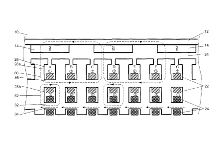
possible transient damping circuit, or "snubber circuit",
uses a resistive element that is switched in to dissipate
voltage transients. Such a resistive snubber circuit is
less efficient as the electrical transients are dissipated
as heat. Accordingly, there is a need to provide
improvements which address these and other limitations of
prior art motor control systems.
SUMMARY
[0003] In one aspect, there is provided an active
electrical protection apparatus for damping electrical
transients in a control circuit of an electrical machine
having phase windings driven using a commutation circuit
and powered through a power supply connection. The
apparatus comprises a power dissipating circuit arranged in
parallel with the commutation circuit, and having a
- 1 -
CA 02639067 2008-08-22
resistive element for dissipating power when electrical
transients are damped and a first switch for switchably
connecting the resistive element; and a controller for
receiving a resonance signal representative of a resonance
condition on the power supply connection, and for
commanding the first switch at least as a function of the
resonance signal.
[0004] In another aspect, there is provided an active
electrical protection apparatus for damping electrical
transients in an electrical machine having phase windings
driven using a commutation circuit and powered through a
power supply connecting line. The apparatus comprises a
power dissipating device arranged in parallel with the
commutation circuit, and having a resistive element for
dissipating power when electrical transients are damped; a
transient suppression device arranged in series with the
power dissipating circuit and with the commutation circuit,
and having a feedback diode device arranged inversely
relative to a drive current of the commutation circuit; a
switching device for switchably connecting the power
dissipating device and for switchably connecting the
transient suppression device; and a switch controller for
receiving a resonance signal representative of a resonance
condition on the power supply connecting line, and for
commanding the switching device at least as a function of
the resonance signal.
[0005] In another aspect, there is provided a method for
damping electrical transients in an electrical machine
having phase windings driven using a commutation circuit.
The method comprises: providing a resistive element
arranged in parallel with the commutation circuit, the
resistive element for dissipating power when electrical
transients are damped; providing a feedback diode device
arranged in series with the power dissipating circuit and
with the commutation circuit, and arranged inversely
- 2 -
CA 02639067 2008-08-22
relative to a drive current of the commutation circuit;
evaluating a resonance condition based on at least one of a
noise level on a power supply line and an operation
frequency of the electrical machine; switching the feedback
diode device in and out as a function of the resonance
condition; measuring a voltage across the commutation
circuit; comparing a value of the voltage to a limit
voltage value to detect a voltage transient which
determines a voltage condition; and switching the resistive
element in and out as a function of the resonance condition
and the voltage condition.
[0006] In another aspect, there is provided a method for
damping electrical transients in an electrical machine
having phase windings driven using a commutation circuit.
The method comprises: providing a resistive element
arranged in parallel with the commutation circuit, the
resistive element for dissipating power when electrical
transients are damped; evaluating an electrical resonance
condition of a power supply line of the electrical machine;
and switching the resistive element in and out as at least
as a function of the electrical resonance condition.
[0007] Further details of these and other aspects will
be apparent from the detailed description and figures
included below.
BRIEF DESCRIPTION OF THE DRAWINGS
[0008] Reference is now made to the accompanying figures
in which:
[0009] Figure 1 is a cross-section of a permanent magnet
motor;
[0010] Figure 2 is a partial schematic of the motor of
Figure 1;
3 -
CA 02639067 2008-08-22
[0011] Figure 3 is a schematic of an arrangement of two
of the motor of Figure 1;
[0012] Figure 4 is a schematic diagram of one channel of
a motor drive circuit for the motors of Figure 3;
[0013] Figure 5 is a cross-sectional view, similar to
Figure 1, of a another arrangement for a motor; and
[0014] Figure 6 is an isometric view of a portion of a
phase winding of the motor of Figure 5; and
[0015] Figure 7 is a schematic diagram of a control
scheme for the motor of Figure 6.
DETAILED DESCRIPTION
[0016] Referring first to Figures 1 and 2, a permanent
magnet (PM) electric machine 10 is depicted. For ease of
illustration and description, Figure 2 shows a linear
arrangement of the electric machine 10 of Figure 1.
However, it is to be understood that the machine 10 may
have the circular architecture of Figure 1, with an inside
or outside rotor. Figure 1 shows an inside rotor. It will
also be understood by the skilled reader that the Figures,
as well as the accompanying description, are schematic in
nature, and that routine details of machine design have
been omitted for clarity, as will be apparent to the
skilled reader. The machine 10 may be configured as an
alternator to generate electrical power, a motor to convert
electrical power into mechanical torque, or both. The
motor aspects of such a machine are primarily of interest
in the following description, and hence machine 10 will now
be referred to as motor 10.
[0017] The motor 10 has a rotor 12 with permanent
magnets 14, interposed by spacers 16, which rotor 12 is
mounted for rotation relative to a stator 20. A retention
sleeve (not shown) is typically provided to hold the
permanent magnets 14 and the spacers 16. Stator 20 has at
4 -
CA 02639067 2008-08-22
least one phase winding 22 and at least one control winding
24 (both windings are represented schematically in the
Figures as a solid rectangles in cross-section, but the
skilled reader will appreciate each may comprise multiple
turns of a conductor, as described below). In the
illustrated embodiment, the stator 20 has a 3-phase design
with three essentially electromagnetically-independent
phase windings 22 (the phases are denoted by the circled
numerals 1, 2, 3, respectively in figure 2) and,
correspondingly, three control windings 24. The phase
windings 22 and control windings 24 are separated in this
embodiment by a winding air gap 26 and are disposed in
radial slots 28, divided into slot portions 28a and 28b,
provided in the stator 20 between adjacent teeth 30. For
ease of description, the adjacent slots 28a, 28b are
indicated in Figure 2 as A, B, C, D, etc. The phase
windings 22 are electrically insulated from the control
windings 24. A back iron 32, also referred to as the
control flux bus 32 in this application, extends between
and at the bottom of the slots 28b. A rotor air gap 34
separates rotor 12 and stator 20 in a typical fashion. A
core or "bridge" portion, also referred to as the "power
flux bus" 36 portion of stator 20 extends between adjacent
pairs of teeth 30 in slot 28 to form the two distinct slots
28a and 28b. The first slots 28a hold the phase windings
22 only, and the second slots 28b hold both the phase
windings 22 and control windings 24.
[0018] The materials for the PM motor 10 may be any one
deemed suitable by the designer. Materials may comprise
samarium cobalt permanent magnets, copper phase and control
windings, a suitable electromagnetic material(s) for the
stator teeth and power and control flux buses, such as
electrical silicon steels commonly used in the construction
of electromagnetic machines. The stator teeth, power and
control flux buses may be integral or non-integral with one
-
CA 02639067 2008-08-22
another, as desired. Each of the phase windings 22 in this
embodiment consists of a conductor with 4 turns per slot,
which enters, for instance, the first slot portion 28a of a
selected slot 28 (e.g. at slot "A"), extends through the
slot and exits the opposite end of the slot, and then
radially crosses the power flux bus 36 to enter the second
slot portion 28b of the same slot 28 (e.g. at slot "A"),
after which it extends back through the length of the
selected slot, to exit the second slot portion 28b, and
hence exits the slot 28 on the same axial side of the
stator as it entered. This path is repeated 4 times to
provide the 4 turns of the phase winding in that slot set
28a, 28b, before proceeding to the next relevant slot set
in the stator. The conductor of phase winding 22 then
proceeds to the second slot 28b of the next selected slot
28 (e.g. slot "D" in Figure 2), where the phase winding 22
then enters and passes along the slot 28, exits and
radially crosses the power flux bus 36, and then enters the
adjacent first slot portion 28a of the selected slot 28,
and then travels through the slot again to exit slot 28a
and the stator adjacent where the winding entered the slot
28b of the selected slot 28. This path is also repeated to
provide the turns of the phase winding in this slot set
28a, 28b, before proceeding to the next relevant slot set
in the stator. The phase winding then proceeds to the next
selected slot 28 (e.g. slot "G"), and so the pattern
repeats. A second phase winding 22 corresponding to phase
2 (not shown), begins in an appropriate selected slot (e.g.
slot B of Figure 2) and follow an analogous path, and may
be wound in an opposite winding direction relative to
winding 22 of phase 1. That is, the phase 2 winding 22
would enter the selected slot (slot B) via slot portion 28b
(since phase 1 winding 22 entered slot A via slot portion
28a, above), and then follows a similar but opposite path
to the conductor of phase 1, from slot to slot (e.g. slots
- 6 -
CA 02639067 2008-08-22
B, E, etc.). Similarly, the phase 3 winding 22 may be
oppositely-wound relative to phase 2, and thus enters the
selected slot (e.g. slot "C") of the stator via slot
portion 28a , and follows the same general pattern as phase
1, but opposite to the pattern of phase 2, from slot to
slot (e.g. slots C, F, etc.). Thus, as mentioned, the
phases of the phase winding 22 are oppositely-wound
relative to one another, for reasons described further
below.
[0019] Meanwhile, a control winding(s) 24 is wrapped
around the control flux bus 32, in a manner as will now be
described. In this embodiment, control winding 24 may form
loops wrapped in a positive turn ratio relative to the
phase winding. In this case, a control-to-phase turns
ratio of 3:2 is contemplated, such that the control winding
is wrapped 6 times around the control flux bus 32 (relative
to the phase winding's 4 turns), for reasons described
below. The control winding 24 and control flux bus 32 thus
provide an integral saturable inductor in stator 20, as
will be discussed below. The direction of winding between
adjacent second slots 28b may be the same from slot to
slot, and thus alternatingly opposite relative to the phase
winding 22 of a same phase wound as described above, so
that a substantially net-zero voltage is induced in each
control winding 24, as will also be described further
below. All loops around the control flux bus 32 may be in
the same direction. Note that the control winding 24 does
not necessarily need to be segregated into phases along
with the phase windings, but rather may simply proceed
sequentially from slot to slot (e.g. slots A, B, C, D,
etc.). Although it is possible to alternate winding
direction of the phase windings, and not alternate
direction of the control windings, the phase and control
windings may be wound in relative opposite directions and
in equal slot numbers to ensure a substantially net-zero
- 7 -
CA 02639067 2008-08-22
voltage is induced in each control winding 24 as a result
of current flow in the phase windings 22, so that the
function described below is achieved. If the control
winding is segregated into phase correspondence with phase
windings 22, for example to reduce its inductance by a
series parallel arrangement, there are potentially equal
numbers of slots of a given phase in which the phase
winding and control winding are wound in opposite
directions, to yield the desired induced net-zero voltage.
[0020] In use, in a motor mode, a 3-phase power source
drives phase windings 22, which result in current flow in
phase windings 22 and a primary magnetic flux along
magnetic flux path or magnetic circuit 60. Interaction of
permanent magnets 14 and primary magnetic flux causes rotor
12 to move relative to stator 20. When the current flow in
phase windings 22 is appropriately controlled, the motor 10
rotates with a speed and torque. A current or voltage
controller appropriately controls the current flow to the
phase windings 22 such that an appropriate speed and torque
is obtained. The current in the control windings in normal
operation of the motor is substantially the same as the
current flow in the phase windings, because they are
connected in series, except that in this embodiment current
may be DC in the control windings, and AC in the phase
windings. The implications for motor control will be
discussed further below.
[0021] Primary magnetic circuit 60 includes rotor 12,
magnets 14, rotor air gap 34, power flux bus 36 and the
portion of stator teeth 30 between rotor 12 and power flux
bus 36. Primary magnetic circuit 60 encircles a portion of
phase winding 22 and is generated in motor 10 by the
combined effect of the rotor magnets and an electrical
current in phase windings 22. Secondary magnetic circuit
62 includes power flux bus 36, control bus 32 and the
portion of stator teeth 30 between control bus 32 and power
- 8 -
CA 02639067 2008-08-22
flux bus 36. In this embodiment, secondary magnetic circuit
62 encircles the portions of the phase winding 22 and
control winding 24 in slot 28b. Power flux bus 36 divides
slot 28 into two slot portions or openings 28a and 28b,
with one opening 28a for the phase winding only, and
another opening 28b for the phase and control windings.
The primary magnetic circuit 60 encircles an opening 28a
while the secondary magnetic circuit 62 encircles an
opening 28b. Opening 28a may be radially closer to the
rotor than opening 28b. Power flux bus 36 is common to
both the primary and secondary AC magnetic circuit paths in
this embodiment. AC current in the phase windings 22
causes a secondary magnetic flux to circulate in the
secondary magnetic circuit 62 when the control bus 64 is
not in a saturated state. The primary and secondary
magnetic circuits are non-overlapping (i.e. non-
intersecting), and remote or isolated from one another. The
secondary magnetic circuit is remote from, and does not
include, the rotor and may be defined wholly within the
stator assembly.
[0022] A tertiary magnetic circuit 64 circulates around
control bus 32, as partially indicated in Figure 2 (i.e.
only a portion of the tertiary circuit is shown, as in this
embodiment the tertiary circuit circulates around the
entire stator 20). The control flux bus 32 may be common
to both the secondary and tertiary magnetic circuit paths
and thus the secondary and tertiary magnetic circuits share
a common portion, namely the control bus 32, as will be
discussed further below. At least a portion of control
flux bus 32 is saturable by the flux density of the
tertiary magnetic circuit.
[0023] Magnetic flux circulates the tertiary magnetic
circuit 64 in the same direction around the control flux
bus 32. As mentioned above, although the control winding
24 is provided in the second slots 28b corresponding to a
- 9 -
CA 02639067 2008-08-22
particular phase of the three-phase machine described, the
phase windings 22 are wound in the opposite direction in
each first slot 28a which is due to the opposite polar
arrangement of the magnets 14 associated with each adjacent
first slot 28a of the phase. To ensure that a uniform
direction for the tertiary magnetic circuit 64 is provided,
as mentioned, the control windings 24 may be wound in the
same direction in all second slots 28b.
[0024] When the control flux bus 32 is magnetically
saturated, the inductance (thus impedance) of the phase
windings is very low, as if there where no secondary AC
magnetic circuit. However, if zero current is applied to
the control winding (i.e. the control winding is open
circuited, or otherwise switched off), the impedance of the
phase windings increases significantly, thus limiting the
current that can flow in the phase windings, which may be
used to remediate, for example, a faulted condition, such
as an internally shorted phase winding or short circuits in
the drive electronics. This impedance control has
beneficial implications for PM motor control, discussed
further below.
[0025] It is to be understood that the above description
applies only to phase "111 of the described embodiment, and
that similar interactions, etc. occur in respect of the
other phases. Further details and aspects of the design and
operation of motor 10 are found in US Patent No. 7,262,539.
[0026] Thus, in use, in a motoring mode, a power source
drives phase windings 22, and control windings 24. As will
be described hereinbelow in reference to Figure 4, in one
example arrangement of the motor drive circuit, the two
windings 22, 24 are effectively connected in series and
thus the control winding current is equivalent (in
magnitude) to the phase winding current. As a result of
the 3:2 turns ratio between these two windings 22, 24, the
- 10 -
CA 02639067 2008-08-22
slightly higher number of turns in the control winding
helps ensure that the control bus is always in a fairly
saturated condition during normal motor operation, so as to
enable efficient functioning of the motor at any drive
current. As discussed above, although the AC flux in the
phase windings 22 tends to cancel out the DC flux in the
control winding 24 in the control bus sections where the
flux directions are in opposition, the 3:2 turn ratio bias
in the control winding 24, prevents the fluxes from
actually cancelling. Thus, when the control flux bus 32 is
magnetically saturated by the action of current flowing
through the control winding 24, the inductance (thus
impedance) of the phase windings 22 is very low, as if
there where no secondary AC magnetic circuit, and hence the
control windings and secondary magnetic circuit would be
essentially "invisible" to the motor during normal motor
operation.
[0027] According to the example arrangement of the motor
drive circuit of Figure 4, the number of turns on the
control winding slots will typically be chosen to be more
than the number of turns in the phase winding slots, so as
to ensure saturation of the control bus (however possibly
not much into saturation, since some inductance in the
control winding is a useful inductor for the buck regulator
filter function as described below) by having just
marginally more ampere turns on the control winding 24 than
on the phase windings 22 in the secondary magnetic circuit.
The DC flux in the control bus typically dominates relative
to the opposing AC flux density in the secondary magnetic
circuit, holding the control bus in saturation down to
quite low relative values of drive current provided via the
control winding 24 to the phase windings 22, even under the
effects of the counter fluxes from the phase windings 22
(i.e. the portion of the phase windings 22 carrying AC in
the negative portion of the cycle tends to reduce
- 11 -
CA 02639067 2008-08-22
saturation of the control flux bus, unless the control
ampere turns are high enough to maintain saturation).
[0028] In use in a fault or shut-down mode, when the
drive current to the motor is at or close to zero, i.e.
such as when the motor is shut down in response to a fault
condition, the control bus de-saturates (as a result of no
control current being supplied) and, as a result, the
interaction between the primary and secondary magnetic
circuits and the inductor-like effect of the control
winding 24, impedes any significant generated currents from
flowing in the phase windings due to continued rotation of
the shut-down motor and any short circuit failure in the
main phase circuits. Further discussion is found in U.S.
Patent 7,262,539.
[0029] Figure 3 shows a redundancy arrangement in which
two motors 10 are co-mounted on the same output shaft 66,
and driven by suitable motor drives 68, each in
communication with a system controller 69, and operated as
described above. If one motor 10 should fail in a short
circuit, open circuit or ground (whether in the motor
itself or the drive electronics or lead wires), the
drive(s) 68 may adjust control of the remaining motor 10
(or motors 10, if there are more than two provided in
total, and two or more are to remain operational in the
event of the shutdown of one) to compensate for the
resulting loss in torque, and the failed motor is no longer
driven. The controller 69 provides the appropriate control
to motor drives 68. As described above, the failed motor
is also in effect disconnected, by bringing current flow in
its control windings to zero, resulting in the impedance of
the phase windings of the failed motor increasing to a high
value, as previously described, such that the drag torque
due to a short circuit type failure is minimized. Motor
failure detection 84 may be achieved using any suitable
approach, such as identifying / measuring / detecting
- 12 -
CA 02639067 2008-08-22
incorrect speed or torque as a function of current,
voltage, high temperature, machine impedance, etc. Failure
detection results in a signal provided to an appropriate
controller for interrupting the current supply to the motor
system (i.e. bringing current flow to zero, as mentioned
above ) .
[0030] Figure 4 shows a simplified example scheme of a
motor drive 68 for driving a motor 10. It should be noted
that the motor 10 schematically depicted in Figure 4
depicts only a single control winding 24 for the three
phases of its associated phase winding set, the control
winding 24 proceeding slot-to-slot in the stator
irrespective of the phase arrangements of the phase
windings 22. As discussed generally above, this is just one
of many control winding arrangements possible, and the
skilled reader will be able to apply the present teachings
to such arrangements in light of the teachings herein.
[0031] The motor 10 is driven by the motor drive 68,
comprising a three-phase H-bridge commutation circuit 70
driving the phase windings 22 of the motor 10. A
commutation control 86 controls the commutation gate drive
88 of the commutation circuit 70 with feedback on the
position of the motor 10, as read by a position sensor 82.
The commutation scheme may be a six-step 120-degree
overlapping scheme in a "make before break" sequence. This
sequence in conjunction with an active snubber 78 reduces
high amplitude voltage spikes occurring at the input of the
inverter (commutation circuit) 70 due to the inductive
effect of the stator windings 22 of motor 10 during motor
commutation.
[00321 Current flow to the motor 10, and thus the
motor's torque and speed, is adjusted using a suitable
pulse width modulated supply system or "buck regulator"
circuit 72 making use of the control winding 24 of the
- 13 -
CA 02639067 2008-08-22
motor 10 as described below. The buck regulator 72 may be
any suitable circuit. The skilled reader will appreciate
that buck regulators typically require a filter inductor as
an energy storage device for stepping down the voltage
level. In this configuration, the buck regulator 72 uses
the control winding 24 as its inductor, thus eliminating
the need for an additional inductor, and consequently
reducing the weight of the buck regulator 72. This filter
inductor replacement role of the control winding 24 may
dictate design features of the control winding 24, as the
designer will consider the buck regulator requirements as
well as the motor requirements in providing a suitable
control winding configuration. The output of the control
winding 24 is connected to the inverter (commutation
circuits) 70, that operates in a six-step mode and provides
AC current to the phase windings 22 of the motor 10.
[0033] In use, the buck regulator 72 varies the current
flow to the phase windings 22 of the motor 10, and thus
controls the torque and speed of the motor 10, based on an
input speed request 76 received from system controller 69
(not shown). Current is provided from a DC source 80 to the
phase windings 22, via the control winding 24, as already
described.
[0034] The buck regulator 72 is controlled by a buck
regulator controller 74 which adjusts the duty cycle of the
buck regulator 72 to control the torque and speed of the
motor 10. The regulator controller 74 receives the speed
request 76, a position feedback signal 84 from the position
sensor 82 and a current feedback signal 92 from a current
transducer 90 measuring the drive current level at the
control windings 24. The position feedback signal 84 is
used to determine a speed error relative to the speed
request 76, and the duty cycle of the buck regulator 72 is
adjusted to vary the level of the drive current. A duty
- 14 -
CA 02639067 2008-08-22
cycle signal 94 is provided to the buck gate drive 96 that
controls switch Ql and Q2 of the buck regulator 72.
[0035] The buck regulator 72, buck regulator controller
74 and buck gate drive 96 are of any suitable type, which
includes suitable types well-known to the skilled reader,
and thus need not be discussed further here.
[00361 An active snubber 78 is used to damp electrical
transients occurring at the input of the inverter
(commutation circuit) 70 due to the inductive effect of the
stator windings 22 of motor 10 during motor commutation.
The active snubber 78 uses a transient suppression feedback
diode 73 for most of the operation frequencies of the motor
10. The power supply may be at some distance away from the
motor control circuitry and current pulses flowing back to
the power supply may cause resonance or noise issues in the
power supply cables at certain motor speeds (or drive
current frequencies) . Accordingly, to avoid line impedance
issues, the active snubber 78 is reconfigurable into a
power dissipating circuit at resonance frequencies of the
power supply network.
[0037] Accordingly, the active snubber 78 has a
transient suppression circuit in series with the
commutation circuit 70 and the power supply cables. The
transient suppression circuit comprises a feedback diode 73
in series with switch Q3 (i.e., a MOSFET transistor) to
switch in and out the feedback diode 73. The feedback diode
73 is connected inversely relative to the drive current so
that voltage pulses at the inductors of the motor 10 are
passed on to the power supply on electrical transients, and
the commutation circuit 70 is thereby protected. The
feedback diode 73 is used (i.e. "in") during most of the
operation of the motor 10 and ensures an efficient
operation of the motor system at most drive frequencies.
- 15 -
CA 02639067 2008-08-22
[0038] However, at resonant frequencies of the power
supply network, voltage pulses due to electrical transients
are damped in a power dissipating circuit, to eliminate the
generation of high voltages and currents that would
otherwise result when the line inductance / impedance
resonates with power supply capacitance at specific
frequencies of motor or buck regulator operation. The power
dissipating circuit is arranged in parallel with the
commutation circuit 70 and comprises a resistive element,
i.e. resistor R1, in series with switch Q4 (i.e. a MOSFET
transistor). The power dissipating circuit is only used
when the drive current corresponds to resonant frequencies.
The feedback diode 73 is then switched "out" and switch Q4
switches R1 "in" in order to damp high-level voltage pulses
at the commutation circuit 70. Accordingly, no more than
one of the resistor R1 and feedback diode 73 is switched
"in" at a time. R1 will depend on the voltage range of the
drive, for low (28) voltage drives this value may be from
0.1 ohm to 2 or 3 ohms, for higher voltage systems the
resistor value will be proportionally higher. It is noted
that the MOSFET switches may be replaces by other types of
devices for high voltage type applications.
[0039] In order to define the switch condition of switch
Q3 and switch Q4, a resonance detector 98 detects an
electrical resonance on the power supply lines using a
current measurement 102 provided by a current transducer
100 installed at the power supply cables, and the position
feedback signal 84 provided by the position sensor 82. The
resonance detector 98 evaluates the frequency of the drive
current using the variation of the position feedback signal
84 in time and also evaluates the amplitude of ripple
component on the nominally direct current of the power
supply cables using line current measurement 102. The
resonance condition is determined as a combination of the
two inputs. It is noted that in this embodiment the
- 16 -
CA 02639067 2008-08-22
frequency of the induced noise ripple on the power supply
lines is six times the motor operation electrical
frequency. Resonance is detected by monitoring the
magnitude of dc link current using current sensor 100. The
motor position feedback signal 82 provides motor rotor
position data that is used to identify ripple on the dc bus
that caused by the motor commutation. A resonance signal
104 representative of a resonance condition on the power
supply line is provided to a switch controller 110.
[00401 The switch controller 110 along with snubber gate
drive 112 controls switch Q3 and switch Q4 of the active
snubber 78. When the noise ripple level on the DC bus is
below a predetermined value, Q3 is closed to switch "in"
the feedback diode 73 and allow transient suppression.
[0041] When a resonance condition is detected by the
resonance detector 98, the feedback diode 73 is switched
"out" and the power dissipating circuit is used to
dissipate high-level voltage pulses typically on a cycle by
cycle basis. Switch Q4 is then controlled as a function a
voltage measurement across the commutation circuit 70 on a
cycle by cycle basis. Accordingly, a voltage signal 108 is
provided by a voltage transducer 106. Switch Q4 is switched
on to switch the resistor Rl "in" and dissipate the
electrical transient when the voltage measurement reaches a
limit instantaneous voltage value, in order to limit
voltage transient across the commutation circuit 70 from
rising above a predetermined limit. Damages to the
commutation circuit 70 are thereby prevented. Voltage
transients are dissipated in resistor R1 instead of being
fed back to the power supply circuit as current pulses,
which limits the noise due to resonance on the power supply
lines and thereby avoids high AC voltages and currents from
occurring in the power supply system. Furthermore, the
dissipating function of the snubber 78 is only used in case
of high voltage transients across the commutation circuit
- 17 -
CA 02639067 2008-08-22
70. A more efficient dissipative snubber is thereby
provided.
[0042] The active snubber 78 advantageously provides an
efficient operation of the motor system at most operation
frequencies except the resonant frequencies of the power
supply network, where the electrical transients are
dissipated in a resistive element as heat.
[0043] Referring again to Figure 3, both motors 10 and
their associated controllers 68 are arranged as described
with reference to Figure 4, to provide a dual redundant
motor system. To enhance redundancy protection, separate
DC sources 80 are provided for each motor system. The
operation of such a dual redundant system according to
Figures 1-5 will now be described.
[0044] Referring again to Figure 3 and to Figure 4, in a
normal operation mode of the motors 10, the drive 68 to
each motor 10 is adjusted so that the motors contribute in
desired proportions to the torque delivered to shaft 66,
and the shaft rotates at a desired speed, as requested by
system controller 69. Both motors 10 may be driven
concurrently to provide torque and, when a higher
efficiency operation or higher power operation is desired,
the respective drives 68 can be adjusted accordingly to
adjust the contribution proportion of each motor 10. The
control winding 24 of each motor 10 functions as the filter
inductor for its respective buck regulation circuit 72, as
described above. Also as described above, the control
winding 24 of each motor may also keep its respective
control bus saturated (by virtue of the relative turns
ratio between phase and control winding) to keep the
control winding otherwise virtually "invisible" to the
motor 10. Should one motor 10 fail, such as in a short
circuit, open circuit or ground, the drive 68 to the other
motor 10 can be adjusted using its buck regulator 72 to
- 18 -
CA 02639067 2008-08-22
increase the AC input to the phase windings 22 of the
operational motor 10 to compensate for the loss in torque
caused by loss of the other motor 10. As the skilled
reader will appreciate, the failed PM motor 10 can tend to
add drag and heat to the system, however with the present
arrangement the failed motor 10, can be "turned off" by no
longer energising the windings (i.e. and thus the current
in the control winding is reduced to zero), which thus
adjusts the failed motor 10 to a high impedance condition
for the phase windings, as already described, thereby
minimizing drag and heat generation. The current to the
respective control windings and inverters is controlled by
external control signals provided to the buck regulator
circuits. If the system controller 69 requests zero
current, then the relevant buck regulator stops providing
current accordingly. This control command may be based on
the system controller 69 detecting a fault or other command
to set the current to zero. The resulting adjustment of the
impedance characteristics of the phase windings of the
affected motor 10, from low impedance during proper motor
function to a high impedance in the failed condition,
results in much improved operation and controllability,
particularly in PM motors where rotor excitation cannot be
independently controlled.
[0045] Figure 5 illustrates a 3-phase, "dual channel" PM
motor 10' according to the general "multi-channel"
principles described in applicant's U.S. Patent No.
6,965,183, but modified in accordance with the above
teachings, as will now be discussed further. The same
reference numerals are used to denote the analogous
elements described with reference to the embodiments above,
and thus all elements will not be redundantly described
here. Stator 20 of dual channel PM machine 10' is
conceptually divided into an "A" half and a "B" half, thus
providing a distinct stator sector for each channel, each
- 19 -
CA 02639067 2008-08-22
channel provided with its own independent winding sets.
Thus windings 22 and 24 will be described in terms of phase
winding sets 22A and 22B and control winding sets 24A and
24B, as discussed further below. Other features associated
with channels A and B are also described as "A" or "B",
specifically, to indicate their respective channels.
[0046] Motor 10' has a multi-channel architecture (in
this case, dual channel), in that a plurality of
circumferentially distributed distinct and fully
independent (i.e. electromagnetically separate) "sets" of
phase and control windings are provided in each stator
sector corresponding to the multiple channels. In this
case, two such sets of 3-phase phase and control windings
are provided, namely a 3-phase set of phase windings 22A
and 22B and respective control windings 24A and 24B (which
happen to be single phase in this embodiment). This multi-
channel architecture provides a plurality of functional
"motor elements" within the same machine structure, which
may either be operated in conjunction, or independently, as
desired. The construction of motor 10' is otherwise
generally as described above with respect to the single
channel embodiment of motor 10.
[0047] The dual channel PM motor 10' provides a single
rotor rotating relative to two effectively independent
stators, or stator sections. Thus, rotor 12 rotates
relative to a stator sector 20A (i.e. the portion of stator
20 with phase windings 22A) and also relative to a stator
sector 20B (i.e. the portion of stator 20 with phase
windings 22B) . When operated as a motor, the two "motors"
(i.e., in effect, motors 10'A and 10'B) are driven
independently, as described generally above with respect to
motor 10, but are synchronized such that they co-operate,
as if only one "motor" is present. In normal motoring mode,
the two "motors" (101A and 10'B) of motor 10' are operated
as described above with respect to motors 10 in Figure 3.
- 20 -
CA 02639067 2008-08-22
Likewise, if one channel of the machine 10' should fail in
a short circuit, open circuit or ground (whether in the
motor 10' itself, or in the drive electronics or lead
wires) , the drive to the remaining channel is adjusted to
compensate for the loss in torque, and the failed channel
is no longer driven. The drive of the failed channel is
effectively disconnected by bringing current flow in the
control windings 22A or 22B to zero, resulting in the
impedance of the phase windings 24A or 24B of the channel
increasing to a high value, as previously described, such
that the drag torque due to a short circuit type failure in
the channel is minimized. This multi-channel configuration
offers two fully redundant systems (i.e. channel A and
channel B) with a minimum of hardware, thereby minimizing
weight and space and increasing reliability. Channel
failure detection may be achieved using any suitable
approach, such as incorrect speed or torque as a function
of current, voltage, high temperature, machine impedance,
etc.
[0048] Referring again to Figure 5, the stator of the
multi-channel motor 10' includes means for impeding cross-
talk between the tertiary magnetic circuits of channels A
and B, such as is described in applicant's co-pending U.S.
Patent application serial no. 11/419,238 filed May 19,
2006. As described in that application, the presence of a
cross-talk reduction feature, such a stator slit 21 acts to
substantially contain the tertiary magnetic flux within the
channel. As such, the tertiary magnetic flux travels along
the entire length of the control flux bus 32 to the channel
boundary, where the presence of the cross-talk reduction
slit 21 redirects the flux up to power flux bus 36, where
it then travels back along entire length of the power flux
bus 36 (this flux is not present, and therefore not
depicted, in the single channel embodiment of Figure 2),
until the path joins up again with the beginning of the
- 21 -
CA 02639067 2008-08-22
tertiary path, in the vicinity of another cross-talk
reduction slit 21.
[0049] Figure 6 shows an isometric free-space view of a
portion of a phase winding 22A of the motor of Figure 4,
but for the fact that only two turns are shown for reasons
of drawing clarity.
[0050] Referring to Figure 7, a control system for dual-
channel motor 10' is shown. Figure 7 is similar to Figure
3, but for the configuration of motor 10' in Figure 7
relative to two motors 10 of Figure 3. Motor drives 68A
and 68B are each as described above with respect to Figure
4, and these two independent motor drives are provided, one
for each channel of motor 10'. In use, a similar operation
is obtained when the control scheme of Figure 4 is applied
to the dual channel motor 10' of Figure 7. Accordingly, in
normal operation, channels A and B may be operated
separately, or conjunctively, and motor drives 68A and 68B
are controlled accordingly by controller 69. When a
failure is detected on one motor channel, the current flow
in its respective control windings 24A or 24B is set to
zero in order to increase impedance of the phase windings
22A or 22B and thereby minimize a drag torque and other
undesirable effects otherwise brought on by the failed
channel.
[0051] The dual-channel design of Figures 6 and 7 offers
obvious size and weight savings over the two motors system
as shown in Figures 4 and S. The two-motor design of
Figure 3 and 5, however, has its own advantages over the
dual-channel arrangement of Figures 6 and 7, such as
simplicity of individual components.
[0052] It is cont"emplated that, although the active
snubber 78 is described herein in conjunction with an
embodiment wherein the motor 10 has control windings 24 and
is used in a dual fail-safe motor configuration, the active
- 22 -
CA 02639067 2008-08-22
snubber circuit 78 can also be advantageously used in the
motor drive circuit of any single motor and of motors
without control windings 24. In any case, the buck
regulator can use an independent inductor winding.
Accordingly, the active snubber 78 described herein is not
limited to this particular application but can be extended
to any other motor drive application.
[0053] The skilled reader will appreciated that the
resonance condition which determines the switch condition
of the active snubber 78 can be determined using variable
inputs. For example, the resonance condition may be
determined according to only the operation frequency of the
motor. If the operation frequency to which resonance noise
appears on the power supply line is predetermined, switch
Q3 and switch Q4 may be controlled as a function of the
operation frequency instead of being a function of the
noise level, the operation frequency being representative
of a resonance condition on the power supply line. The
operation frequency may be determined using the position
sensor 82 or, alternatively, the speed request signal 76
could be used as an input of the resonance detector 98.
[0054] While a combination of the current ripple
amplitude on the power supply lines and of the frequency of
the position feedback signal is used in the illustrated
embodiment to determine the resonance condition, one will
understand that a single one of the current ripple
amplitude and the frequency of the motor could
alternatively be used.
[0055] Furthermore, other parameters can alternatively
be used to evaluate the resonance condition. For example, a
temperature measurement on the power supply lines or
elsewhere could be used to evaluate the resonance
condition.
- 23 -
CA 02639067 2008-08-22
[00561 The skilled reader will appreciate that a failure
is not required to turn a channel or motor "off" as
described above, but rather the approach may be used in any
suitable situation where it is desired to shut a channel
"off", including as part of a normal operation scheme.
[0057] In another control scheme, the dual motor
arrangement of Figure 3, or as the case may be, the dual
channel motor of Figure 7, is controlled using a modified
motor drive in which buck regulator 72 has a dedicated
filter inductor independent from the control windings 24.
Separate DC current sources respectively drive the phase
and control windings independently from one another. Phase
windings may be driven as described above so that torque is
split as desired among the motors or channels in normal
operation, during which time the DC source provides control
current at a sufficient level to keep the control flux bus
fully saturated at all times, for reasons already
described. In the event of a channel failure, phase
winding current in the other motor/channel is adjusted to
compensate for the loss of torque due to the failed
channel, while the current from source 81 to the control
winding(s) for the failed channel is brought to zero to
minimize the drag torque due to the failed channel.
[0058] In this embodiment, the control winding has
different design constraints than those of the above
embodiments, and thus the control winding may have a higher
number of turns relative to the phase windings, to minimise
the amount of control current required to saturate and
maintain saturation in under the influence of desaturating
fluxes from the main phases.
[00591 In the arrangement of Figure 7, where the control
current is supplied from a source separate from the phase
windings, and is independently variable relative to the
phase windings, if the phase winding current in the
- 24 -
CA 02639067 2008-08-22
motor/channel exceeds a specific value, such as a desired
maximum limit, the inductance of the phase winding will
abruptly increase, tending to limit the current in the
phase winding to that specific value or limit. This can be
used to simplify the drive system of very low impedance
(i.e. high speed) PM motors. For example, the motor can be
designed using this feature to intrinsically limit inrush
current on start-up by appropriately designing this feature
into the motor, such that other typical inrush limiting
techniques, such as duty cycle control, may be omitted or
operated at lower frequencies.
[0060] The above description is meant to be exemplary
only, and one skilled in the art will recognize that
changes may be made to the embodiments described without
departing from the scope of the embodiments disclosed.
Such modifications are intended to fall within the scope of
appended claims.
25 -