Note: Descriptions are shown in the official language in which they were submitted.
CA 02639343 2008-09-04
METHOD AND SYSTEM FOR
GOVERNING BLOCK SPEED
FIELD OF THE INVENTION
The present invention generally pertains to equipment used for drilling,
preparing,
repairing, and evaluating wells. More specifically the present invention
pertains to
methods and systems for governing the speed of a block based on the tasks to
be
performed at the well.
BACKGROUND OF THE INVENTION
After drilling a hole through a subsurface formation and determining that the
formation can yield an economically sufficient amount of oil or gas a crew
completes the
well. Once completed, a variety of events may occur to the formation causing
the well
and its equipment to require a "work-over." For purposes of this application,
"work-over"
and "service" operations are used in their very broadest sense to refer to all
activities
performed on or for a well to repair or rehabilitate the well, and also
includes activities to
shut in or cap the well. Generally, workover operations include such things as
replacing
worn or damaged parts (e.g., a pump, sucker rods, tubing, and packer glands),
applying
secondary or tertiary recovery techniques, such as chemical or hot oil
treatments,
cementing the wellbore, and logging the wellbore, to name just a few.
During drilling, completion, and well servicing, personnel routinely insert
into
and/or extract equipment such as tubing, tubes, pipes, rods, hollow cylinders,
casing,
conduit, collars, and duct from the well. For example, a service crew may use
a workover
or service rig (collectively hereinafter "service rig" or "rig") that is
adapted to, among other
things, pull the well tubing or rods and also to run the tubing or rods back
into the well.
Typically, these mobile service rigs are motor vehicle-based and have an
extendible,
jack-up derrick complete with draw works and block. The crew may inspect the
extracted
tubing and evaluate whether one or more sections of that tubing should be
replaced due
to physical wear, thinning of the tubing wall, chemical attack, pitting, or
other defects.
The crew typically replaces sections that exhibit an unacceptable level of
wear and note
CA 02639343 2008-09-04
- other sections that are beginning to show wear and may need replacement
at a
subsequent service call.
During rod or tubing removal, a rig operator typically lifts a stand of tubing
(or
rods) which is then held in place by slips (or elevators for rods) while the
stand is
separated from the remaining portion of the tubing or rod string in the well.
Once the
stand of tubing has been separated from that which is still in the well, the
stand of tubing
can be placed on a tubing board. During conventional lifting operations, the
rig operator
has a full range of control of the speed at which the tubing or rods are
lifted out of the
well. With this, operators have a tendency to want to remove the rods, tubing
or other
equipment out of the well as quickly as possible in order to complete the job
in a timely
manner. However, by removing equipment from the well at a speed that is too
high, the
opportunities for damaging the well, the equipment, and the workers around the
well
dramatically increases.
In addition, as the stands of tubing (or rods) are being pulled out of the
well, the
total amount of weight on the string is reduced and the length of the string
is reduced.
When there are only a few stands of tubing left in the well, pulling the
tubing out at a
typical rate of speed, can become more dangerous because, if the tubing snags
or
drags in the well, there is less overall elasticity within the remaining
length of tubing, and
therefore, less time to react to problems caused by the hang-up in the well.
This too
can cause dangerous conditions around the wellhead.
Furthermore, during logging operations or when the equipment, such as tubing,
is being inspected within the well the inspection data can be misleading if
the logging
equipment or the tubing (when the logging equipment is stationary) is being
pulled too
quickly, thereby limiting the usefulness of the inspection data.
Therefore, there is a need in the art for a system and method for monitoring
the
block speed for a rig during a pulling or running operation and limiting the
maximum
allowable speed of the block, thereby limiting the speed of the equipment that
is
attached to the hook of the rig. Furthermore, what is needed is a method and
apparatus
for evaluating the task being completed by a rig and the hookload and/or rig
load to
determine if the speed of the block should be limited to a maximum allowable
speed.
Furthermore what is needed in the art is a method for evaluating the task
being
2
CA 02639343 2008-09-04
= =
- completed by a rig and the amount of equipment remaining in the well to
determine if
the speed of the block should be limited to a maximum allowable speed. In
addition,
what is needed in the art is a system and method for disabling the lock-up
system for a
transmission driving the block when the hookload is light or only a small
portion of the
equipment, such as tubing, remains in the well during a pulling operation.
The present invention is directed to solving these as well as other similar
issues
in the well service area.
SUMMARY OF THE INVENTION
A method for governing the speed of a block based on the task that is being
completed can include receiving a task input at a well service rig. The
maximum
allowable speed can be determined based on the task. An encoder or other speed
evaluating device can provide an input for the current block speed as it
accomplishes
the task. The throttle position for the engine controlling the block can be
evaluated to
determine if the block is to be sped up or slowed down. When the throttle
position
indicates the operator is attempting to speed up the block, the current block
speed can
be compared to the maximum allowable speed. If the current speed is below the
maximum allowable speed but the change would increase it above the maximum
allowable speed, the signal to the engine can be managed to limit the block's
velocity up
to the maximum allowable speed, at which point the operators control of block
speed is
limited to reducing block speed. If the current speed is below the maximum
allowable
speed and the change would not increase the block speed above the maximum
allowable speed, the operator can be allowed to maintain full control of the
block speed
through the throttle controls. Each task can have multiple maximum allowable
speeds,
which can vary based on specified conditions, such as hookload, rig load, or
the amount
of equipment remaining in the well. In addition, when the hookload is light or
the
remaining equipment in the well is small, the lock-up feature for the
transmission can be
disengaged in addition to the block speed governing feature.
For one aspect of the present invention, a method for controlling the speed of
a
block on a well service rig can include receiving the block speed from a speed
analysis
device. An input for the current position of the throttle, through which the
rig operator
3
CA 02639343 2008-09-04
,
controls the speed of the engine and thereby the speed of the block, can be
accepted.
An evaluation of the throttle input can be conducted to determine if the
operator is
attempting to increase the block speed above a maximum allowable speed. The
maximum allowable speed can be input by the operator or stored within a
computer,
processor or analysis device. The block speed can then be limited to the
maximum
allowable speed if the input for the current position of the throttle would
have raised the
block speed above the maximum allowable speed.
For another aspect of the present invention, a method for controlling block
speed
can include an input for the task to be completed being accepted at a speed
evaluation
computer or processor at the well service rig. A maximum allowable speed can
be
determined or calculated based on the received task at the speed evaluation
computer.
An input for the throttle position and the current block speed can be accepted
at the
speed evaluation computer. An evaluation of the throttle input can be
conducted to
determine if the operator is attempting to increase the block speed above a
maximum
allowable speed. The block speed can then be limited to the maximum allowable
speed
if the input for the current position of the throttle would have raised the
block speed
above the maximum allowable speed.
For yet another aspect of the present invention, a method for controlling
block
speed on a well service rig can include an input for the task to be completed
being
accepted at a speed evaluation computer at the well service rig. A
predetermined
hookload weight can be stored in or received at the speed evaluation computer.
A
maximum allowable speed can be determined or calculated based on the received
task
and the predetermined hookload weight at the speed evaluation computer. An
input for
the throttle position, the current block speed, and the current hookload
weight can be
accepted at the speed evaluation computer. The speed evaluation computer or
another
computer can determine if the current hookload weight is equal to or below the
predetermined hookload weight. Based on a positive determination that the
current
hookload weight is equal to or below the predetermined hookload weight, the
speed
evaluation computer can prevent the throttle input from increasing the block
speed
above the maximum allowable speed.
4
CA 02639343 2008-09-04
For another aspect of the present invention, a system for controlling the
speed of
a block on a well service rig can include a throttle sensor for determining if
the operator
is attempting to speed-up or slow-down the engine, and thereby the speed of
the block.
The system can also include a block speed sensor for determining the current
speed of
the block. The system can further include a task input display for receiving
the task
being completed at the well. The system can also include an engine electronic
controller for receiving a signal from the throttle sensor or a speed
evaluator and
converting that into an increase or decrease in speed of the engine, and
correspondingly the block as well. The system can also include a speed
evaluator,
such as a computer or processor, for receiving task, throttle and block speed
information and determining if the block is already at or will go above a
maximum
allowable speed. The speed evaluator can generate a signal to the engine
electronic
controller that is different from the throttle input and limits the speed of
the engine and
thereby the speed of the block to the maximum allowable speed.
BRIEF DESCRIPTION OF DRAWINGS
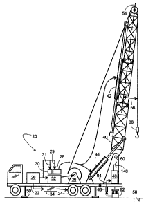
Figure 1 is a side view of an exemplary mobile repair unit with its derrick
extended according to one exemplary embodiment of the present invention;
Figure 2 is a side view of the exemplary mobile repair unit with its derrick
retracted according to one exemplary embodiment of the present invention;
Figure 3 is an electrical schematic of a monitor circuit according to one
exemplary embodiment of the present invention;
Figure 4 illustrates the raising and lowering of an inner tubing string with
an
exemplary mobile repair unit according to one exemplary embodiment of the
present
invention;
Figure 5 illustrates one embodiment of an activity capture methodology
outlined
in tabular form according to one exemplary embodiment of the present
invention;
Figure 6 provides a frontal view of an exemplary operator interface according
to
one exemplary embodiment of the present invention;
5
CA 02639343 2008-09-04
Figure 7 is a schematic diagram of a system that monitors block speed based on
a given task and activates a speed governing feature according to one
exemplary
embodiment of the present invention;
Figure 8 is an exemplary display of the results of a speed governing feature
on
the block speed as compared to air pressure based on throttle position
according to one
exemplary embodiment of the present invention;
Figure 9 is a logical flowchart diagram presenting the steps of an exemplary
process for limiting the maximum block speed based on the task to be completed
in
accordance with one exemplary embodiment of the present invention; and
Figure 10 is a logical flowchart diagram presenting the steps of an exemplary
process for limiting the maximum block speed and disabling the lock-up system
for a
transmission based on the task to be completed and the load on the system in
accordance with one exemplary embodiment of the present invention.
DETAILED DESCRIPTION OF THE EXEMPLARY EMBODIMENTS
Exemplary embodiments of the invention will now be described in detail with
reference to the included figures. The exemplary embodiments are described in
reference to how they might be implemented. In the interest of clarity, not
all features of
an actual implementation are described in this specification. Those of
ordinary skill in
the art will appreciate that in the development of an actual embodiment,
several
implementation-specific decisions must be made to achieve the inventors'
specific
goals, such as compliance with system-related and business-related constraints
which
can vary from one implementation to another. Moreover, it will be appreciated
that such
a development effort might be complex and time-consuming, but would
nevertheless be
a routine undertaking for those of ordinary skill in the art having benefit of
this
disclosure. Further aspects and advantages of the various figures of the
invention will
become apparent from consideration of the following description and review of
the
figures. While references are generally made hereinafter to rods or tubing
specifically,
with the description of the figures, each reference should be read broadly to
include
rods, tubing, piping, and other downhole equipment unless specifically limited
therein.
6
CA 02639343 2008-09-04
, .
-
_
Referring to Figure 1, a retractable, self-contained mobile repair unit 20 is
presented to include a truck frame 22 supported on wheels 24, an engine 26, a
hydraulic pump 28, an air compressor 30, a first transmission 32, a second
transmission
34, a variable speed hoist 36, a block 38, an extendible derrick 40, a first
hydraulic
cylinder 42, a second hydraulic cylinder 44, a first transducer 46, a monitor
48, and
retractable feet 50.
The engine 26 selectively couples to the wheels 24 and the hoist 36 by way of
the transmissions 34 and 32, respectively. The engine 26 also drives the
hydraulic
pump 28 via the line 29 and the air compressor 30 via the line 31. The
compressor 30
powers a pneumatic slip (Not Shown), and the pump 28 powers a set of hydraulic
tongs
(Not Shown). The pump 28 also powers the cylinders 42 and 44 which
respectively
extend and pivot the derrick 40 to selectively place the derrick 40 in a
working position,
as shown in Figure 1, and in a lowered position, as shown in Figure 2. In the
working
position, the derrick 40 is pointed upward, but its longitudinal centerline 54
is angularly
offset from vertical as indicated by the angle 56. The angular offset provides
the block
38 access to a wellbore 58 without interference with the derrick pivot point
60. With the
angular offset 56, the derrick framework does not interfere with the typically
rapid
installation and removal of numerous inner pipe segments (known as pipe, inner
pipe
string, rods, or tubing 62, hereinafter "tubing" or "rods").
Individual pipe segments (of string 62 in Figure 4) and sucker rods are
screwed
to themselves using hydraulic tongs. The term "hydraulic tongs" used herein
and below
refer to any hydraulic tool that can screw together two pipes or sucker rods.
An
example would include those provided by B. J. Hughes company of Houston,
Texas. In
operation, the pump 28 drives a hydraulic motor (Not Shown) forward and
reverse by
way of a valve. Conceptually, the motor drives the pinions which turn a wrench
element
relative to a clamp. The element and clamp engage flats on the mating
couplings of a
sucker rod or an inner pipe string 62 of one conceived embodiment of the
invention.
However, it is well within the scope of the invention to have rotational jaws
or grippers
that clamp on to a round pipe (i.e., no flats) similar in concept to a
conventional pipe
wrench, but with hydraulic clamping. The rotational direction of the motor
determines
assembly or disassembly of the couplings.
7
CA 02639343 2008-09-04
, .
While not explicitly shown in the figures, when installing the tubing segments
62,
the pneumatic slip is used to hold the tubing 62 while the next segment of
tubing 62 is
screwed on using tongs. A compressor 30 provides pressurized air through a
valve to
rapidly clamp and release the slip. A tank helps maintain a constant air
pressure.
Pressure switch provides the monitor 48 (Figure 3) with a signal that
indirectly indicates
that the rig 20 is in operation.
Referring back to Figure 1, weight applied to the block 38 is sensed by way of
a
hydraulic pad 92 that supports the weight of the derrick 40. The hydraulic pad
92 is
basically a piston within a cylinder (alternatively a diaphragm) such as those
provided
by M. D. Totco company of Cedar Park, Texas. Hydraulic pressure in the pad 92
increases with increasing weight on the block 38. In Figure 3, the first
transducer 46
converts the hydraulic pressure to a 0-5 VDC signal 94 that is conveyed to the
monitor
48. The monitor 48 converts signal 94 to a digital value, stores it in a
memory 96,
associates it with a real time stamp, and eventually communicates the data to
a remote
computer 100 or the computer 605, of Figure 6, by way of hardwire, a modem 98,
Ti
line, WiFi or other device or method for transferring data known to those of
ordinary skill
in the art.
Returning to Figure 3, transducers 46 and 102 are shown coupled to the monitor
48. The transducer 46 indicates the pressure on the left pad 92 and the
transducer 102
indicates the pressure on the right pad 92. A generator 118 driven by the
engine 26
provides an output voltage proportional to the engine speed. This output
voltage is
applied across a dual-resistor voltage divider to provide a 0-5 VDC signal at
point 120
and then passes through an amplifier 122. A generator 118 represents just one
of
many various tachometers that provide a feedback signal proportional to the
engine
speed. Another example of a tachometer would be to have engine 26 drive an
alternator and measure its frequency. The transducer 80 provides a signal
proportional
to the pressure of hydraulic pump 28, and thus proportional to the torque of
the tongs.
A telephone accessible circuit 124, referred to as a "POCKET LOGGER" by
Pace Scientific, Inc. of Charlotte, N.C., includes four input channels 126,
128, 130 and
132; a memory 96 and a clock 134. The circuit 124 periodically samples inputs
126,
128, 130 and 132 at a user selectable sampling rate; digitizes the readings;
stores the
8
CA 02639343 2008-09-04
digitized values; and stores the time of day that the inputs were sampled. It
should be
appreciated by those skilled in the art that with the appropriate circuit, any
number of
inputs can be sampled and the data could be transmitted instantaneously upon
receipt.
A supervisor at a computer 100 remote from the work site at which the service
rig
20 is operating accesses the data stored in the circuit 124 by way of a PC-
based
modem 98 and a cellular phone 136 or other known methods for data transfer.
The
phone 136 reads the data stored in the circuit 124 via the lines 138 (RJ11
telephone
industry standard) and transmits the data to the modem 98 by way of antennas
140 and
142. In an alternative embodiment the data is transmitted by way of a cable
modem or
WiFi system (Not Shown). In one exemplary embodiment of the present invention,
the
phone 136 includes a CELLULAR CONNECTION.TM. provided by Motorola
Incorporated of Schaumburg, Ill. (a model S1936C for Series II cellular
transceivers and
a model S1688E for older cellular transceivers).
Some details worth noting about the monitor 48 is that its access by way of a
modem makes the monitor 48 relatively inaccessible to the crew at the job site
itself.
However the system can be easily modified to allow the crew the capability to
edit or
amend the data being transferred. The amplifiers 122, 144, 146 and 148
condition their
input signals to provide corresponding inputs 126, 128, 130 and 132 having an
appropriate power and amplitude range. Sufficient power is needed for RC
circuits 150
which briefly (e.g., 2-10 seconds) sustain the amplitude of inputs 126, 128,
130 and 132
even after the outputs from transducers 46, 102 and 80 and the output of the
generator
118 drop off. This ensures the capturing of brief spikes without having to
sample and
store an excessive amount of data. A DC power supply 152 provides a clean and
precise excitation voltage to the transducers 46, 102 and 80; and also
supplies the
circuit 124 with an appropriate voltage by way of a voltage divider 154. A
pressure
switch 90 enables the power supply 152 by way of the relay 156, whose contacts
158
are closed by the coil 160 being energized by the battery 162. Figure 4
presents an
exemplary display representing a service rig 20 lowering an inner pipe string
62 as
represented by arrow 174 of Figure 4.
Figure 5 provides an illustration of an activity capture methodology in
tabular
form according to one exemplary embodiment of the present invention. Now
referring to
9
CA 02639343 2008-09-04
Figure 5, an operator first chooses an activity identifier for his/her
upcoming task. If
"GLOBAL" is chosen, then the operator would choose from rig up/down, pull/run
tubing
or rods, or laydown/pickup tubing and rods (options not shown in Figure 6). If
"ROUTINE: INTERNAL" is selected, then the operator would choose from rigging
up or
rigging down an auxiliary service unit, longstroke, cut paraffin, nipple
up/down a BOP,
fishing, jarring, swabbing, flowback, drilling, clean out, well control
activities such as
killing the well or circulating fluid, unseating pumps, set/release tubing
anchor,
set/release packer, and pick up/laydown drill collars and/or other tools.
Finally, if
"ROUTINE: EXTERNAL" is chosen, the operator would then select an activity that
is
being performed by a third party, such as rigging up/down third party
servicing
equipment, well stimulation, cementing, logging, perforating, or inspecting
the well, and
other common third party servicing tasks. After the activity is identified, it
is classified.
For all classifications other than "ON TASK: ROUTINE," a variance identifier
is selected,
and then classified using the variance classification values.
Figure 6 provides a view of an rig operator interface or supervisor interface
according to one exemplary embodiment of the present invention. Now referring
to
Figure 6, all that is required from the operator is that he or she input in
the activity data
into a computer 605. The operator can interface with the computer 605 using a
variety
of means, including typing on a keyboard 625 or using a touch-screen 610. In
one
embodiment, a touch-screen display 610 with pre-programmed buttons, such as
pulling
rods or tubing from a wellbore 615, is provided to the operator, as shown in
Figure 6,
which allows the operator to simply select the activity from a group of pre-
programmed
buttons. For instance, if the operator were presented with the display 610 of
Figure 6
upon arriving at the well site, the operator would first press the "RIG UP"
button. The
operator would then be presented with the option to select, for example,
"SERVICE
UNIT," "AUXILIARY SERVICE UNIT," or "THIRD PARTY." The operator then would
select whether the activity was on task, or if there was an exception, as
described
above. In addition, as shown in Figure 6, prior to pulling (removing) 615 or
running
(inserting) rods 62, the operator could set the high and low limits for the
block 38 by
pressing the learn high or learn low buttons after moving the block 38 into
the proper
position.
CA 02639343 2008-09-04
, .
Turning now to Figure 7, a schematic diagram of a system for monitoring the
block speed for a well service rig based on a given task and regulating the
speed of the
block 38, through engine speed, if a maximum allowable speed for the task is
reached,
is presented according to one exemplary embodiment of the present invention.
Referring now to Figure 7, the exemplary system 700 includes a throttle
operator input
705, an analog-to-digital converter 710, a speed evaluator 715, the computer
605, an
engine controller 720 and a governor relay 725. In one exemplary embodiment,
the
system is designed to be compatible with electronically controlled engines,
such as the
engine 26 for the well service rig 20.
The throttle operator input 705 is communicably coupled to the analog-to-
digital
converter 710. The throttle operator input 705 provides a range of pneumatic
pressures, such as between 0-120 pounds per square inch ("psi") of air
pressure, to the
analog-to-digital converter 710 based on the position in which the rig
operator places
the throttle for the engine 26. While the present invention is described in
terms of
providing a pneumatic pressure to designate throttle position, those of
ordinary skill in
the art will recognize that other methods may be used within the bounds of
this
invention including, but not limited to, a potentiometer or rheostat type
control, which are
not shown but are well known in the art. In an alternative embodiment, the
throttle
position could be determined and a digital signal could be provided by the
throttle
operator input 705, thereby eliminating the need for the analog-to-digital
converter 710.
The analog-to-digital converter 710 is communicably coupled to the throttle
operator input 705, the speed evaluator 715, the governor relay 725, and the
engine
electronic controller 720. In one exemplary embodiment, the analog-to-digital
converter
710 generates between one and five volts of direct current based on the input
from the
throttle operator input 705 to signal the desired operating speed 735 for the
engine 26,
and thereby the block 38 of the rig 20. The speed evaluator 715 is
communicably
coupled to the analog-to-digital converter 710, the encoder input 730, the
computer 605
and the engine electronic controller 720. The speed evaluator 715 receives a
signal
representing the speed of the block 38 from the encoder input 730. In one
exemplary
embodiment, the encoder input 730 is from a traveling block-driven device
which can be
a drum-driven quad-type encoder, a hall effect sensor mounted near a moving
part,
11
CA 02639343 2012-12-28
r =
such as near the hoist 36, or any other device that will input a proportional
signal based
on the speed of the block 38 or the hoist 36.
The speed evaluator 715 also receives an input from the computer 605, in the
form of the task to be completed. In one exemplary embodiment, the task to be
completed or currently being completed is input by the rig operator on the
touch-screen
610. In an alternative embodiment, the computer 605 can evaluate several data
inputs
of the rig 20 to determine the activity being completed at the rig 20 without
operator
intervention. In addition, the speed evaluator 715 receives an input from the
analog-to-
digital converter 710 in the form of a one-to-five volt direct current signal
representing
the throttle position. In one exemplary embodiment, the speed evaluator 715 is
a
computer, processor, microprocessor or other similar device. The speed
evaluator 715
can receive the task to be completed, the current speed of the block 38 and
the speed
desired by the operator in the form of the throttle operator input 705 and
determine if the
maximum allowable speed of the block 38, based on the given task, has been
reached.
The speed evaluator 715 can output a signal 740, in the form of a one to five
volt direct
current signal, to control the speed of the engine 26, and thereby the speed
of the block
38, to the engine electronic controller 720 based on whether the maximum
allowable
speed has been reached for the given task.
The engine electronic controller 720 is communicably coupled to the governor
relay 725, the speed evaluator 715, and the engine 26. In one exemplary
embodiment,
the engine electronic controller 720 adjusts the fuel-to-air mixture for the
engine 26
based on the desired speed of the engine 26, which is determined from external
input,
such as the analog-to-digital converter 710 or the speed evaluator 715. Once
the speed
evaluator 715 has determined if the speed should be governed and generated a
signal
for the speed of the engine 26 based on the several inputs, the engine
electronic
controller 720 can receive the signal form the speed evaluator 715 and
regulate the
speed of the engine 26 for the rig 20.
In one exemplary embodiment, the above-described system 700 could act such
that, if the desired operating speed from the rig operator 735 is less than
the maximum
allowable block speed for the rig 20, the speed evaluator 715 would allow the
operator,
through the throttle operator input 705, to have full control of the block
speed through
12
CA 02639343 2012-12-28
. õ
_
the engine 26. In the alternative, if the desired operating speed from the rig
operator
735 is greater than the maximum allowable block speed for the given task, the
speed
evaluator 715 would send a signal to the engine electronic controller 720 that
is different
from the signal being sent by the throttle operator input 705, through the
analog-to-
digital controller 710, that limits the speed of the engine 26, and thereby
the speed of
the block 38, to the maximum allowable speed.
While not shown, the speed evaluator 715 could also receive a hookload input
for
the load on the block 38 or the entire load of the rig 20. The hookload input
can be
generated based on a signal from the hydraulic pad 92 or any other techniques
known
to those of ordinary skill in the art for measuring hookload or rig load.
In certain exemplary embodiments, the maximum allowable speed may not only
be a function of the task being completed, but may also be adjusted or
enforced based
on the amount of hookload, rig load, or the amount of tubing 62 in the well
58. For
example, when pulling tubing 62 from the well 58, the maximum allowable speed
may
be set at four feet per second when the hookload is high or there is a lot of
tubing 62 still
in the well. However, when the hookload is below five thousand pounds or there
is less
than one thousand feet of tubing 62 in the well 58, the maximum allowable
speed can
be set at two feet per second.
While not shown in Figure 7, the system 700 can also include a relief valve,
such
as an electrical relief valve, in a pressure line to the lock-up actuating
cylinder (Not
Shown) for the transmission lock-up system. The conventional automatic
transmission
32 includes a torque converter that provides slippage between the engine 26
and the
transmission. This torque converter allows the engine 26 to build up speed or
horsepower while lifting heavy loads. Internal to the transmission 32 is a
lock-up
system which, in one exemplary embodiment, is a direct coupling mechanical
clutch.
While lifting the hookload and when the engine speed, in revolutions per
minute ("rpm"),
matches the transmission input shaft rpm, the transmission 32 no longer needs
the
torque converter slippage. At this point the transmission 32 engages the lock-
up clutch
by applying hydraulic pressure to a cylinder, thereby taking the torque
converter out of
the drive train. In certain situations, the lock-up feature can be dangerous
if it is
engaged and the rig 20 pulls the tubing 62 into an unexpected obstacle in the
well 58, or
13
CA 02639343 2012-12-28
. .
into the slips, wellhead 186 or a blowout preventer. In these situations, with
the lock-up
engaged, the momentum of the engine 26 and drive train transfers without
slippage to
the hoist 36 and increases the chance of pulling the tubing 62 apart.
In this
embodiment, the speed evaluator 715 can be programmed to disable the lock-up
system in the transmission 32 by sending a signal to the electrical relief
valve, thereby
insuring slippage in the transmission 32.
Figure 8 is an illustration of an exemplary display 800 of block speed as
compared to throttle position based on the air pressure from the throttle
operator imput
705 according to one exemplary embodiment of the present invention. Now
referring to
Figures 1, 4, 7 and 8, the exemplary display 800 includes a block speed chart.
The
block speed chart includes a series of block speed data points based on, for
example,
the operator air input pressure from the throttle operator input 705 on the
rig 20. While
it appears from the chart that the block speed data points are being recorded
on a
constant basis, it is possible to take the data points at intervals and
generate the line or
curve based on the averages over a period of data points. The X-axis of the
block
speed chart 800 represents operator input air pressure from the throttle
operator input
705, represented in psi. The Y-axis of the block speed chart 800 represents
block
speed in feet per second ("FPS").
For the purpose of explanation, the chart 800 includes two exemplary speed
curves 805 and 835. Referring to speed curve 805, as air pressure is
increased, the
block speed has a corresponding increase up to point 815, where the speed
evaluator
715 begins to govern the speed of the block 38 due to the fact that the
maximum
allowable speed has been reached for the given task. After point 815, as air
pressure
continues to increase based on the throttle operator input 705, the speed
curve 805 is
represented by two separate curves, curve 810, which represents the speed the
block
38 would achieve without activating the speed governing feature, and curve
820, which
represents the speed of the block 38 being maintained at the maximum allowable
speed
for that task even though the air pressure continues to increase.
In another example, referring to speed curve 835, as air pressure is
increased,
the block speed has a corresponding increase up to point 845, where the speed
evaluator 715 begins to govern the speed of the block 38 due to the fact that
the
14
CA 02639343 2012-12-28
maximum allowable speed has been reached for the given task. After point 845,
as air
pressure continues to increase, based on the throttle operator input 705, the
speed
curve 835 is represented by two separate curves, curve 840, which represents
the
speed the block 38 would achieve without activating the speed governing
feature, and
curve 850, which represents the speed of the block 38 being maintained at the
maximum allowable speed for that task even though the air pressure continues
to
increase. Based on the block speed curves 805 and 835 for the chart 800, in
the
pressure range 825, the operator would have full control of the speed of the
blocks 38.
However, in the pressure range 830, the operator would only have control of
the block
speed below the maximum allowable speed. Any attempt by the operator to
increase
the block speed will result in the block 38 continuing to operate at the
maximum
allowable speed.
Processes of exemplary embodiments of the present invention will now be
discussed with reference to Figures 9 and 10. Certain steps in the processes
described
below must naturally precede others for the present invention to function as
described.
However, the present invention is not limited to the order of the steps
described if such
order or sequence does not alter the functionality of the present invention in
an
undesirable manner. That is, it is recognized that some steps may be performed
before
or after other steps or in parallel with other steps without departing from
the scope and
spirit of the present invention.
Furthermore, while the present invention will be
described for exemplary purposes in relation to a well service rig 20, it
should be
understood that the processes are not limited to use with the rig 20 but can
be
employed with other types of well-related machinery and in environments
outside the
well service or well related industry.
Turning now to Figure 9, a logical flowchart diagram illustrating an exemplary
method 900 for limiting the maximum block speed based on the task to be
completed is
presented according to one exemplary embodiment of the present invention.
Referring
to Figures 1, 4, 6, 7, and 9, the exemplary method 900 begins at the START
step and
continues to step 905, where information on the task to be completed or that
is being
completed is received. In one exemplary embodiment, the task is entered by the
operator at the computer 605 using the touch-screen 610. For example, prior to
pulling
CA 02639343 2012-12-28
,
tubing 62 the rig operator could select the pull option 615 at the computer
605. In an
alternative embodiment, the computer 605 can evaluate several data inputs of
the rig 20
to determine the activity being completed at the rig 20 without operator
intervention.
In step 910, the maximum allowable speed for the task is determined. In one
exemplary embodiment, the maximum allowable speed for each task is a
predetermined
amount stored in the computer 605 and/or the speed evaluator 715. In an
alternative
embodiment, the maximum allowable speed can be received as an input from the
operator at the computer 605 on the rig 20. While the exemplary embodiment is
described as a maximum allowable speed, each task may have one or more maximum
allowable speed limits based on different conditions, such as rig load,
hookload, well
conditions, amount of tubing 62, rods or other tubulars remaining in the well
58, the type
of equipment used in the operation, such as the type of rig 20, or other
factors known to
those of ordinary skill in the art. For example, a rig 20 pulling tubing 62
from the well 58
may generally have a maximum allowable speed of four feet per second. However,
once there is less than five thousand pounds of hookload and or approximately
one
thousand linear feet of tubing 62 remaining in the well 58, the maximum
allowable
speed can be reset at two feet per minute. In another example, a rig 20
pulling rods
from the well 58 may generally have a maximum allowable speed of eight feet
per
second. However, once there is less than five thousand pounds of hookload and
or
approximately two thousand linear feet of rods 62 remaining in the well 58,
the
maximum allowable speed can be reset at three feet per minute. Furthermore,
the
maximum allowable speed may be constructed so that it is adjustable at the
computer
605 or the speed evaluator 715. The adjustability of the maximum allowable
speeds
can be based on customer requirements, current conditions, or the experience
of the rig
operator.
The throttle position is received in step 915. In one exemplary embodiment,
the
throttle position is received from the throttle operator input 705 through the
analog-to-
digital converter 710 at the speed evaluator 715. In step 920, the speed
evaluator 715
receives the block 38 speed. In one exemplary embodiment, the block 38 speed
is
received from a drum-driven quad-type encoder at the hoist 36, a hall effect
sensor
mounted adjacent a moving part between the hoist 36 and the block 38, or any
other
16
CA 02639343 2012-12-28
device that provides an input proportional signal based on the speed of the
block 38 or
the hoist 36. In step 925, an inquiry is conducted to determine if the speed
of the block
38 is to be increased based on the throttle operator input 705. If not , the
"NO" branch
is followed to step 930.
In step 930, an inquiry is conducted to determine if the block speed is below
the
maximum allowable speed. In one exemplary embodiment, this determination can
be
made at the speed evaluator 715 by comparing the current input from the
encoder 730
to the stored maximum allowable speed for the task being completed. If the
speed is
currently below the maximum allowable speed, the "YES" branch is followed to
step
935, where the operator of the rig 20 is given full control of the block
speed. The
process can then return from step 935 to step 915 to continue analyzing the
throttle
position. On the other hand, if the block speed is not currently below the
maximum
allowable speed, the "NO" branch is followed to step 940.
In step 940, an inquiry is conducted to determine if the throttle input would
reduce the block speed below the maximum allowable speed. If not, the "NO"
branch is
followed to step 945, where the governor relay 725 remains activated and the
speed is
maintained at the maximum allowable speed . At this point, the operator does
not have
full range of control of the block speed. The process returns from step 945 to
step 915
to continue monitoring the throttle position. Returning to step 940, if the
throttle input
would reduce the block speed below the maximum allowable speed, the "YES"
branch
is followed to step 935, where the governor relay 725 is deactivated once the
speed of
the engine 26 drops so that the speed of the block 38 will be below the
maximum
allowable speed and the operator is given control of the block speed below the
maximum allowable speed. The process returns from step 935 to step 915 to
continue
analyzing the throttle position.
Returning to step 925, if the speed of the block 38 is being increased based
on
the throttle position, the "YES" branch is followed to step 950. In step 950,
an inquiry is
conducted to determine if the speed of the block 38 is currently at the
maximum
allowable speed. If so, the "YES" branch is followed to step 955, where the
governor
relay 725 is maintained in the activated position and the speed of the block
38 is
maintained at the maximum allowable speed. On the other hand, if the speed of
the
17
CA 02639343 2012-12-28
= -
A
block 38 is not currently at the maximum allowable speed, the "NO" branch is
followed
to step 960. In step 960, an inquiry is conducted to determine if the speed
increase
requested by the operator based on throttle position takes the speed of the
block 38
above the maximum allowable speed. If not, the "NO" branch is followed to step
965,
where the operator is allowed to freely control the speed of the block 38
through the use
of the throttle. The process continues from step 965 to step 915 to continue
monitoring
the throttle position. On the other hand, if the speed of the block reach the
maximum
allowable speed and will exceed it based on the throttle position, the "YES"
branch is
followed to step 970. In step 970, the operator is allowed to control the
block speed
through the throttle up to the maximum allowable speed. Once the maximum
allowable
speed is reached, the governor relay 725 is activated and the speed evaluator
715
sends a signal 740 to the engine electronic controller 720 that maintains the
speed of
the block 38 at the maximum allowable speed. The process continues to step 915
to
continue monitoring the throttle position.
Figure 10, a logical flowchart diagram illustrating an exemplary method 1000
for
limiting the maximum block speed and disabling the lock-up system for the
transmission
32 based on the task to be completed and the load on the rig 20 presented
according to
one exemplary embodiment of the present invention. Referring to Figures 1, 4,
6, 7, 9,
and 10, the exemplary method 1000 begins at the START step and continues to
step
1005, where information on the task to be completed or that is being completed
is
received. In one exemplary embodiment, the task is entered by the operator at
the
computer 605 using the touch-screen 610. For example, prior to pulling tubing
62 the
rig operator could select the pull option 615 at the computer 605. In an
alternative
embodiment, the computer 605 can evaluate several data inputs of the rig 20 to
determine the activity being completed at the rig 20 without operator
intervention.
In step 1010, the maximum allowable speed for the task is determined. In one
exemplary embodiment, the maximum allowable speed for each task is a
predetermined
amount stored in the computer 605 and/or the speed evaluator 715. In an
alternative
embodiment, the maximum allowable speed can be received as an input from the
operator at the computer 605 on the rig 20. While the exemplary embodiment is
described as a maximum allowable speed, each task may have one or more maximum
18
CA 02639343 2012-12-28
. ,
allowable speed limits based on different conditions, such as rig load,
hookload, well
conditions, amount of tubing 62, rods or other tubulars remaining in the well
58, the type
of equipment used in the operation, such as the type of rig 20, or other
factors known to
those of ordinary skill in the art.
In step 1015, an inquiry is conducted to determine if the maximum allowable
speed is based on the rig load or the hookload for the rig 20. If not, the
"NO" branch is
followed to step 915 of Figure 9 and the process follows that as substantially
described
in Figure 9. Otherwise, the "YES" branch is followed to step 1020, where the
hookload
or rig load is evaluated. The hookload or rig load can be generated based on a
signal
from the hydraulic pad 92 or any other techniques known to those of ordinary
skill in the
art for measuring hookload or rig load, such as other types of load gauges
including, but
not limited to, strain gauges, line indicators and the like. The load
information can be
received at the computer 605 and/or the speed evaluator 715 for analysis and
comparison to the maximum allowable speed.
In step 1025, an inquiry is conducted to determine if a predetermined hookload
or
rig load has been reached. For example, as described above, when the rig 20 is
pulling
tubing 62 from the well 58, the maximum allowable speed can be reduced from
four feet
per second to two feet per second when the hookload falls below five thousand
pounds.
If the predetermined hookload or rig load has not been reached, the "NO"
branch is
followed back to step 1020 to continue evaluation of the hookload. On the
other hand, if
19
CA 02639343 2008-09-04
the predetermined hookload or rig load level has been reached, the "YES"
branch is
followed to step 1030, where the upper level of the block speed is limited to
the
maximum allowable speed when the operator tries to speed up the block 38 above
the
maximum allowable speed. The process of maintaining block speed at or below
the
maximum allowable speed is substantially as described in Figure 9. In step
1035, the
speed evaluator 715 can transmit a signal to disable the lock-up system for
the
transmission. In one exemplary embodiment, the signal can activate a relief
valve, such
as an electrical relief valve, in a pressure line to the lock-up actuating
cylinder for the
transmission lock-up system. In step 1040, the speed evaluator 715 continues
to
monitor the throttle position through the throttle operator input 705 to
determine if the
block speed needs to be limited to the maximum allowable speed. The process
continues from step 1040 to step 1030 for further evaluation of the throttle
position as
compared to the maximum allowable speed for the task and rig load or hookload.
Although the invention is described with reference to preferred embodiments,
it
should be appreciated by those skilled in the art that various modifications
are well
within the scope of the invention. Therefore, the scope of the invention is to
be
determined by reference to the claims that follow. From the foregoing, it will
be
appreciated that an embodiment of the present invention overcomes the
limitations of
the prior art. Those skilled in the art will appreciate that the present
invention is not
limited to any specifically discussed application and that the embodiments
described
herein are illustrative and not restrictive. From the description of the
exemplary
embodiments, equivalents of the elements shown therein will suggest themselves
to
those or ordinary skill in the art, and ways of constructing other embodiments
of the
present invention will suggest themselves to practitioners of the art.
Therefore, the
scope of the present invention is to be limited only by any claims that
follow.