Language selection

Search

Patent 2639399 Summary

Third-party information liability

Some of the information on this Web page has been provided by external sources. The Government of Canada is not responsible for the accuracy, reliability or currency of the information supplied by external sources. Users wishing to rely upon this information should consult directly with the source of the information. Content provided by external sources is not subject to official languages, privacy and accessibility requirements.

Claims and Abstract availability

Any discrepancies in the text and image of the Claims and Abstract are due to differing posting times. Text of the Claims and Abstract are posted:

  • At the time the application is open to public inspection;
  • At the time of issue of the patent (grant).
(12) Patent Application: (11) CA 2639399
(54) English Title: WIND ENGINE
(54) French Title: MOTEUR EOLIEN
Status: Dead
Bibliographic Data
Abstracts

English Abstract


The wind engine with vertical axis of rotation has retractable vanes which
allow to
eliminate need for mechanism of wind turbine rotation in case of wind
direction change,
and increase differential torque. The wind engine also includes possibility to
increase
power of wind turbine by stacking impellers, by allowing of stacked units have
opposite
direction of rotation and double the generator speed, also added option to add
non-linear
transmission to increase power output.


Claims

Note: Claims are shown in the official language in which they were submitted.


THE EMBODIMENTS OF THE INVENTION IN WHICH AN EXCLUSIVE
PROPERTY OR PRIVILAGE IS CLAIMED ARE DEFINED AS FOLLOWS:


1. A wind engine comprising of at least one impeller, at least two vanes,
several
hinges assemblies, at least one output shaft; said hinges allow vanes up to
ninety degree
oscillation by having movement limiter; said impeller and output shaft have
synchronous
rotation by wind energy utilization.

2. A wind engine having at least two wind engines as claimed in claim 1
stacked with
rotational shift to each other to stabilize output torque and having one
common output
shaft.

3. A wind engine having two wind engines as claimed in claims 1 and 2 stacked;
said
one set to have opposite direction of rotation and having separate output
shafts arranged
as telescopic output shaft.

4. A wind engine comprising wind engines as claimed in claims 1, 2 and 3 and
non-
linear gearing arrangement to optimize output according user requirements.

-4-

Description

Note: Descriptions are shown in the official language in which they were submitted.


CA 02639399 2008-09-15
TITLE: WIND ENGINE

FIELD OF THE INVENTION

The present invention relates to wind turbines and in particular, to wind
turbines with vertical axis of rotation in order to increase their
effectiveness.

BACKGROUND OF THE INVENTION

Various designs have been proposed for wind turbines with vertical axis
of rotation including usage of impellers with twisted vanes similar to fans,
also
impellers with vanes having difference in aerodynamic characteristics from
opposite sides. All those designs use difference in aerodynamic properties of
vanes when they face air flow twice during each rotation creating resulting
torque for impeller which is applied to drive alternator/generator. Also most
of
wind turbines require rotational mechanism for positioning impeller
perpendicular to wind direction. In some cases in order to increase alternator
or generator speed of rotation gear boxes are used, which leads to some loss
of
torque distributed to alternator/generator.
The present invention overcomes a number of above problems and also
improves wind engine performance resulting in wind turbine structure
simplification by removing the need of positioning, significantly increasing
resulting torque of wind engine and allowing in some cases to remove gear box
or replace/combine it with non-linear transmission to improve
alternator/generator performance

SUMMARY OF THE INVENTION

A wind engine according to the present invention is part of wind turbine
that actually converts wind energy into rotary motion of alternator/generator
or
pump comprises vertical axis rotating impellers which could be disc or other

- 1 -


CA 02639399 2008-09-15

structure capable to secure several vanes and allow mounting of hinges which
allow vanes oscillation and securing their position along axis of rotation
once during each half rotation facing wind pressure and, after this to float
in
opposite direction not more than 90 degree depending on wind speed; vanes
with shape allowing maximum utilization of wind energy during their position
along plane parallel to impeller axis of rotation and minimum wind resistance
when floating another half of rotation with maximum wind speed almost
reaching plane perpendicular axis of rotation considerably increasing
differential torque created by opposing vanes.

In a preferred aspect of invention each impeller assembly has at least two
preferably diagonally opposed oscillating vanes, and each wind engine has at
least one impeller assembly and shaft with coupling connecting wind engine
with non-linear transmission gear box or directly to alternator/generator.

In an aspect of the invention wind engine has several impeller assemblies
on one shaft stacked above each other with angular shift to each other, to
reduce torque variation and rotating in the same direction.
In a preferred aspect of the invention wind engine has several impeller
assemblies on telescopic shafts stacked above each other rotating in opposite
direction with one shaft coupled to rotor and another to stator of
alternator/generator doubling its speed of rotation.
In an aspect of the invention wind engine includes special gear box with
non-linear transmission to maximize performance of the connected
alternator/generator.

BRIEF DESCRIPTION OF THE DRAWINGS

Embodiments of the invention are shown in the drawings, wherein:
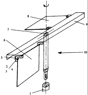
Figure 1 is a view of variation of simplest wind engine configuration
showing impeller with two vanes and location of hinges and movement
limiters.

- 2
-


CA 02639399 2008-09-15

Figure 2 is a view of wind engine with stacked impeller assemblies
connected to telescopic shaft and coupled to alternator/generator.

DETAILED DESCRIPTION OF THE EMBODIMENTS

The wind engine Figure 1 shows impeller in form of long channel 9
and two hinge assemblies 4 with bearings 3, movement limiters 2 and hinge
shafts 5 holding vane 6 facing wind pressure 10.
This pressure creates torque on wind engine output shaft 7. At
the same time opposite vane 8 is floating under wind pressure with limited
resistance creating considerable differential torque. After another 90 plus
degree rotation vane 8 starts to face wind and slowly starts to gain torque
with
maximum torque reaching at position previously occupied by vane 6. Figure 1
shows the need to have more than 2 vanes for overlapping, with preferred four
vanes, depending on length of channel 9 this number can go higher.

The wind engine Figure 2 has two stacked impellers assemblies 21 and 22
rotating in opposite direction with telescopic shaft 23-24 with internal shaft
23
connected to rotor 25 of generator and external shaft 24 connected to stator
26
creating double speed without gear box use.

The present invention disclose unique addition of vanes oscillation during
impellers rotation allowing eliminate need of repositioning of wind engine
with
wind direction change, increase differential pressure and torque, also allows
stacking of impellers and in some cases increases rotational speed of
alternator/generator.
Also it is recommended to include as part of wind engine a non-linear
transmission to increase utilization of output power for different
applications
such as generator, pumps, etc. as explained in my patent pending for SLT
device.

-3-

Representative Drawing
A single figure which represents the drawing illustrating the invention.
Administrative Status

For a clearer understanding of the status of the application/patent presented on this page, the site Disclaimer , as well as the definitions for Patent , Administrative Status , Maintenance Fee  and Payment History  should be consulted.

Administrative Status

Title Date
Forecasted Issue Date Unavailable
(22) Filed 2008-09-15
Examination Requested 2009-05-11
(41) Open to Public Inspection 2010-03-15
Dead Application 2011-09-15

Abandonment History

Abandonment Date Reason Reinstatement Date
2010-09-15 FAILURE TO PAY APPLICATION MAINTENANCE FEE
2011-01-14 R30(2) - Failure to Respond

Payment History

Fee Type Anniversary Year Due Date Amount Paid Paid Date
Application Fee $200.00 2008-09-15
Request for Examination $400.00 2009-05-11
Owners on Record

Note: Records showing the ownership history in alphabetical order.

Current Owners on Record
AROV, ANATOLY
Past Owners on Record
None
Past Owners that do not appear in the "Owners on Record" listing will appear in other documentation within the application.
Documents

To view selected files, please enter reCAPTCHA code :


To view images, click a link in the Document Description column. To download the documents, select one or more checkboxes in the first column and then click the "Download Selected in PDF format (Zip Archive)" or the "Download Selected as Single PDF" button.

List of published and non-published patent-specific documents on the CPD .

If you have any difficulty accessing content, you can call the Client Service Centre at 1-866-997-1936 or send them an e-mail at CIPO Client Service Centre.


Document
Description 
Date
(yyyy-mm-dd) 
Number of pages   Size of Image (KB) 
Representative Drawing 2010-02-26 1 8
Cover Page 2010-02-26 2 34
Abstract 2008-09-15 1 14
Description 2008-09-15 3 135
Claims 2008-09-15 1 26
Drawings 2008-09-15 2 26
Correspondence 2008-10-16 1 13
Assignment 2008-09-15 2 273
Prosecution-Amendment 2009-05-11 1 13
Prosecution-Amendment 2010-07-14 3 87