Note: Descriptions are shown in the official language in which they were submitted.
CA 02639890 2013-10-24
1
MULTI-ZONE PAPER FIBER REFINER
BACKGROUND OF THE INVENTION
[0001] The invention relates to a refiner comprising a stator and a
rotor, the stator and the rotor comprising a planar portion and a conical
portion
after the planar portion, the planar portion and the conical portion
comprising
refining surfaces provided with blade bars and blade grooves therebetween,
and the planar portions of the refining surfaces of the stator and the rotor
;!. = comprising at least two refining zones in the direction of the
radius (R) of the
planar portion.
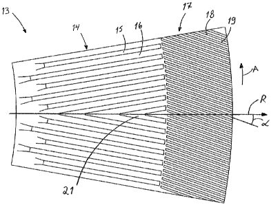
[0002] The invention further relates to a blade segment of a refining
surface of a refiner, which blade segment is configurable to form at least
part
of the refining surface of the stator or the rotor of the refiner and which
comprises blade bars and blade grooves therebetween, which together form
the refining surface of the blade segment, and which blade segment is
provided with at least two refining zones in the direction of the radius of
the
refining surface.
[0003] Refiners for processing fibrous material typically comprise
two, but possibly also more, oppositely situated refining surfaces, at least
one
of which is arranged to rotate about a shaft such that the refining surfaces
turn
.1! 20 with
respect to one another. The refining surfaces of the refiner, i.e. its blade
surfaces or the blade set, typically consist of protrusions, i.e. blade bars,
provided in the refining surface and blade grooves between the blade bars.
Hereinafter, blade bars may also be referred to as bars and blade grooves as _
grooves. The refining surface consists of a plural number of juxtaposed blade
segments, in which case the refining surfaces of individual blade segments
together form an integral, uniform refining surface.
[0004] WO 97/18037 discloses a refiner provided with a stator, i.e. a
fixed, immobile refiner element, and a refiner element to be rotated by means
of a shaft, i.e. a rotor. Both the stator with its refining surface and the
rotor with
its refining surface are formed of a planar portion substantially
perpendicular to
the rotor shaft and a conical portion provided after this planar portion and
arranged at an angle to the planar portion. The planar and conical portions of
the stator and the rotor are spaced apart such that a blade gap is formed
between the refining surface of the stator and the refining surface of the
rotor.
The fibrous material to be refined is fed into the blade gap between the
planar
CA 02639890 2008-07-21
PCT/FI2007/050047
26 Nov 2007
2
portions of the stator and the rotor. As the material to be refined is being
processed, it moves forward in the blade gap into the blade gap between the
conical portions of the stator and the rotor and finally away from the blade
gap.
[0005] A problem with the refiner type disclosed in WO 97/18037 is
the turning point formed by the planar portion and the conical portion,
because
already the change it causes in the direction of travel of the material to be
refined complicates the feeding of the material to be refined from the planar
portion to the conical portion. This harmful effect is further aggravated by
the
fact that also the point of inversion and the high pressure of steam created
in
the refining process set in this same area. The fibres therefore remain long
at
this location and get accumulated there, which in turn leads to high energy
consumption and high pressure, which tends to open the refiner blades and
thereby cause additional stress on the refiner structure.
SUMMARY OF THE INVENTION
[0006] An object of the invention is a novel refiner providing
enhanced feed of fibrous material from the planar portion to the conical
portion.
[0007] The refiner of the invention is characterized in that at least
the planar portion of the refining surface of the rotor is provided with blade
bars
in its outermost refining zone in the direction of the radius, the blade bar
angle
of the blade bars being arranged so as to provide pumping blade bars, and
their blade bar angle being greater at least on the outermost portion of the
outermost refining zone of the planar portion than the blade bar angle of the
blade bars in the previous refining zone in the direction of the radius of the
planar portion and that the blade bar angle of the pumping blade bars of said
outermost refining zone is 5 - 50 degrees so that the blade bars in the
outermost refining zone have an overall pumping effect on the material to be
refined.
[0008] A blade segment of the invention is characterized in that in
its outermost refining zone in the direction of the radius, the refining
surface is
provided with blade bars, the blade bar angle of the blade bars being arranged
so as to provide pumping blade bars when the refiner is in use, and their
blade
bar angle being greater at least on the outermost portion of the outermost
refining zone of the refining surface than the blade bar angle of the blade
bars
in the previous refining zone in the direction of the radius of the refining
surface
and that the blade bar angle of the pumping blade bars of the outermost
AMENDED SHEET (IPEA/FI)
CA 02639890 2008-07-21
WO 2007/085703 PCT/F12007/050047
3
refining zone is 5 - 50 degrees so that the blade bars in the outermost
refining
zone have an overall pumping effect on the material to be refined.
[0009] The refiner comprises a stator and a rotor, the stator and the
rotor comprising a planar portion and a conical portion after the planar
portion.
The planar portion and the conical portion further comprise refining surfaces
provided with blade bars and blade grooves between the blade bars, the
planar portions of the refining surfaces of the stator and the rotor
comprising at
least two refining zones in the radial direction of the planar portions.
Further, at
least in the radially outermost refining zone of the planar portion of the
refining
surface of the rotor, there are provided blade bars configured to form blade
bars having a pumping blade bar angle, their blade bar angle being greater at
least on the outermost portion of the outermost refining zone of the refining
surface than the blade bar angle of the blade bars in the previous refining
zone
in the radial direction of the planar portion, and that the blade bar angle of
the
pumping blade bars in the outermost refining zone is 5 - 50 degrees so that
the
blade bars in the outermost refining zone have an overall pumping effect on
the material to be refined.
[0010] A pumping blade bar is a blade bar that produces in the
mass particle to be refined both a circular velocity component and a radial
velocity component directed away from the centre of the refining surface. The
direction of the blade bar angle between the pumping blade bar and the
refining surface radius is opposite to the direction of rotation of the
refiner
blade, this direction of the blade bar angle being referred to the positive
direction of the blade bar angle.
[0011] This allows an improved material feed from the planar
portion of the refiner to its conical portion to be obtained. Compared with
prior
art solutions, the residence time of the fibres to be refined is shortened and
their accumulation is reduced at the transition point between the planar
portion
and the conical portion. When mass feed from the refiner's planar portion to
its
conical portion is to be enhanced without substantially affecting the quality
of
the mass or the specific energy consumption of the refiner, a small blade bar
angle that nevertheless enhances flow from the planar portion to the conical
portion is selected. Although a small blade bar angle does not significantly
change energy consumption, feed from the planar portion to the conical portion
is enhanced such that the production capacity of the refiner can be increased.
At the same time, the axial forces of the refiner are reduced. When the energy
CA 02639890 2008-07-21
WO 2007/085703 PCT/F12007/050047
4
consumption of the refiner is to be decreased, a greater blade bar angle is
selected. Compared with prior art solutions, a blade bar angle of 10 - 40
degrees or 20 to 35 degrees, for example, provide not only enhanced feed but
also significant energy savings in refining.
BRIEF DESCRIPTION OF THE FIGURES
[0012] Some embodiments of the invention will be discussed in
greater detail with reference to the accompanying figures, in which
Figure 1 is a schematic view of a refiner in which the disclosed
refining surface solution can be applied;
Figure 2 is a schematic view of a blade segment of a planar portion
of a refiner;
Figure 3 is a schematic view of a second blade segment of a planar
portion of a refiner;
Figure 4 is a schematic view of a third blade segment of a planar
portion of a refiner;
Figure 5 is a schematic view of a fourth blade segment of a planar
portion of a refiner;
Figure 6 is a schematic cross-sectional view of a detail in the
refining surface of the planar portion of the refiner stator and in the
refining
surface of the planar portion of the refiner rotor.
[0013] For the sake of clarity, some embodiments of the invention
are simplified in the Figures. Like parts are indicated with like reference
numerals.
A DETAILED DISCLOSURE OF SOME EMBODIMENTS OF THE INVENTION
[0014] Figure 1 is a schematic view of a refiner 1 for refining fibrous
material. The refiner 1 is provided with a fixed stator 2, supported to a
frame 1
not shown in Figure 1, the stator 2 comprising a frame part 3 of the stator 2
and a refining surface 4 consisting of blade bars and blade grooves, i.e. a
refiner blade- or blade set. Further, the refiner 1 is provided with a rotor
6,
arranged to be rotated by a shaft 5 and motor, not shown, the rotor 6
comprising a frame part 7 of the rotor 6 and a refining surface 8 consisting
of
blade bars and blade grooves, i.e. a refiner blade or blade set. The refining
surface 4 of the stator 2 consists of a planar portion 4', which is arranged
substantially perpendicularly to the shaft 5, and a conical portion 4", which
is
arranged at a predetermined angle to the planar portion 4'. Correspondingly,
CA 02639890 2008-07-21
WO 2007/085703 PCT/F12007/050047
the refining surface 8 of the rotor 6 consists of a planar portion 8', which
is
arranged substantially perpendicularly to the shaft 5, and a conical portion
8",
which is arranged at an angle to the planar portion 8' corresponding to the
angle between the planar portion 4' and the conical portion 4" of the stator
5 refining surface 4. The rotor 6 is arranged at a distance from the stator
2 in
such a way that a blade gap 11 is left between the refining surface 8 of the
rotor 6 and the refining surface 4 of the stator 2. The size of the blade gap
of
the conical portion and the planar portion may be preferably adjusted by
moving the rotor 6 closer to or further away from the stator 2 by means of the
shaft 5. The blade gap of the planar portion may be adjusted separately by
moving the stator 2 of the planar portion closer to or further away from the
rotor
6. The fibrous material to be refined is fed by means of a feed screw 12, for
example, through the centre of the planar portions 4', 8' of the refining
surfaces
4 and 8 to the blade gap 11, where the fibrous material is refined and, at the
same time, it moves between the planar portion 4' of the refining surface 4 of
the stator 2 and the planar portion 8' of the refining surface 8 of the rotor
6
towards a portion between the conical portions 4', 8' in the blade gap 11 and
finally away from the blade gap 11. A person skilled in the art is familiar
with
the general structure and operating principle of refiners and therefore they
shall not be discussed further in this context.
[0015] Figure 2 is a schematic view of a blade segment 13 in the
planar portion 8' of the refining surface 8 of a rotor 6, the segment being
meant
to form part of the integral refining surface of the planar portion 8' of the
rotor
6. A similar blade segment may naturally be used also in the planar portion 4'
of the refining surface 4 of the stator 2. The blade segment 13 of Figure 2 is
provided with two refining zones, a first or inner refining zone 14 in the
direction of the refining surface radius R and a second or outer refining zone
17 in the direction of the refining surface radius R. The refining zone 14
comprises blade bars 15 and blade grooves 16 between the blade bars. The
blade bars 15 take care of refining the fibrous material to be refined and the
blade grooves 16 carry forward the fibrous material to be refined as well as
the
refined material and also take care of conveying the steam created during the
refining away from the blade gap 11. As the refining of the fibrous material
proceeds, the material to be refined moves forward from the inner refining
zone 14 to the outer refining zone 17, i.e. to the outermost refining zone 17,
when seen in the direction of the radius R of the blade segment 13. The
CA 02639890 2008-07-21
WO 2007/085703 PCT/F12007/050047
6
refining zone 17 further comprises blade bars 18 and blade grooves 19 which
in Figure 2 are narrower than the blade bars and the blade grooves of the
inner refining zone 14 in order for a greater refining efficiency. The blade
bars
18 of the outer refining zone 17 are configured so as to provide pumping blade
bars by adjusting the blade bar angle a between the blade bars 18 and the
' radius R of the refining surface of the planar portion at a specific
angle in
relation to the radius R, the blade bar angle a being greater than the angle
between the blade bars 14 in the inner refining zone 14 and the radius R of
the
refining surface in the planar portion. The blade bar angle a between the
radius R and the blade bars 17 of the outer refining zone may be 5 - 50
degrees, for example.
[0016] A pumping blade bar is a blade bar that produces for a mass
particle to be refined both a circular velocity component and a velocity
component directed away from the centre of the refining surface in the
direction of the radius R of the refining surface. The blade bar angle a
between
a pumping blade bar and the radius R of the refining surface is thus directed
opposite to the direction of rotation of the refining surface as shown in
Figure
2, where arrow A indicates the direction of rotation of the rotor 6. This
blade
bar direction is typically referred to as the positive direction of the blade
bar
angle. The direction of the blade bars 18 naturally also determines the
direction of the blade grooves 19.
[0017] Figure 2 shows an arrangement of the blade bars of the
outer refining zone 17, or the outermost refining zone of three or more
refining
zones, on the outer periphery of the refining surface, which enables to
improve
the feed of the material to be refined from the planar portion of the refiner
1 to
its conical portion. Compared with prior art solutions, the residence time of
the
fibres to be refined in the transition point between the planar portion and
the
conical portion is decreased and their accumulation is reduced. A small blade
bar angle, which nevertheless enhances flow from the planar portion to the
conical portion, enables a sufficient improvement of feed from the planar
portion to the conical portion to be obtained without substantially affecting
the
quality of the mass. Compared with the small angle, a large blade bar angle
enhances the feed from the planar portion to the conical portion more, thus
allowing the energy consumption of the refiner to be reduced. Consequently,
the selected blade bar angle a is preferably 10 - 40 degrees, more preferably
20 - 35 degrees, which enable not only more efficient feed but also
CA 02639890 2008-07-21
WO 2007/085703 PCT/F12007/050047
7
considerable energy savings in the refining to be obtained in comparison with
prior art solutions. The blade bar angle of the refining zone before the
outermost refining zone being smaller than the blade bar angle of the pumping
blade bars in the outermost refining zone prevents the material to be refined
from moving too quickly away from the blade gap in the planar portion of the
refiner, and therefore the quality of the refined material is not impaired.
[0018] In the blade segment of Figure 2 the blade bars 18 of the
outermost refining zone 17 are all pumping blade bars, and their blade bar
angle a remains constant in the direction of the refining surface radius R
from
the centre of the refining surface towards the periphery of the refining
surface.
Figure 3 shows a blade segment 13, in which the blade bar angle a of the
blade bars 18 in the outermost refining zone 17 increases in the direction of
the refining surface radius R from the centre of the refining surface towards
the
periphery of the refining surface. In the blade segment of Figure 3, the blade
bars are curved in such a way that the blade bars at the beginning of the
outermost refining zone, i.e. on the side of the inner refining zone, are
substantially parallel to the radius R, but the blade bar angle a increases
relatively quickly towards the periphery of the blade segment, whereby the
blade bars 18 at least on the outermost portion of the outermost refining zone
17 of the refining surface are pumping blade bars.
[0019] Figure 4 in turn shows a blade segment 13 which has three
refining zones, an innermost refining zone 14 provided with blade bars 15 and
blade grooves 16, an outermost refining zone 17 provided with blade bars 18
and blade grooves 19, and, between the innermost refining zone 14 and the
outermost refining zone 17, a middle refining zone 23 provided with blade bars
24 and blade grooves 25. In the blade segment 13 of Figure 4 only part of the
blade bars 18 in the outermost refining zone 17 in the direction of the
refining
surface radius R are arranged to be pumping, as described above, and to
thereby enhance the feed of the fibrous material to be refined from the planar
portion of the refiner 1 to its conical portion. The blade bar angle a of the
pumping blade bars 18 of the blade segment 13 of Figure 4 is selected such
that the blade bars of the outermost refining zone 17 of the blade bars of the
outermost refining zone produce an overall pumping effect on the material to
be refined, i.e. the outermost refining zone provides a resultant pumping
effect
that enhances the flow from the planar portion to the conical portion,
irrespective of whether there are also retentive blade bars in the outermost
CA 02639890 2008-07-21
WO 2007/085703 PCT/F12007/050047
8
refining zone or blade bars that have no effect on the travel of the mass in
the
blade gap.
[0020] A retentive blade bar is a blade bar that produces in the
mass particle to be refined both a circular velocity component and a velocity
component in the direction of the radius R towards the centre of the refining
surface. In other words, a retentive blade set tends to prevent the fibrous
material to be refined from moving away from the blade gap.
[0021] Figure 5 shows a blade segment 13, where the blade bars
15, 18 of both the inner refining zone 14 and the outer refining zone 17 are
curved, although such that the blade bar angle ot of the blade bars 18 in the
outer refining zone 17 is greater in relation to the radius R of the refining
surface than the blade bar angle of the blade bars 15 in the inner refining
zone
14. Figure 5 further shows schematically flow dams 20 arranged on the bottom
of the blade grooves 16 and 19 and responsible for restricting and guiding the
flow of the material to be refined.
[0022] The refining surface solutions of Figures 2 - 5 show two or
three refining zones. However, four or more refining zones are also possible,
in
which case the refining zone that is outermost in the direction of the
refining
surface radius R is provided with blade bars arranged at least on a part of
the
length in the direction of the refining surface periphery, the blade bars
being
pumping and their blade bar angle in relation to the radius R is greater than
that of the blade bars of the previous refining zone in the direction of the
refining surface radius R, and the blade bar angle of the blade bars in the
outermost refining zone being 5 - 50 degrees. The disclosed blade bar solution
may be provided either solely on the refining surface of the rotor or on the
refining surface of both the rotor and the stator. If the mass quality is to
be left
substantially unaffected, the outermost refining zone on the planar portion 4'
of
the refining surface 4 may be arranged retentive, whereby the angle of
incidence between the blade bars of the outermost refining zones of the rotor
refining surface and the stator refining surface remains small. The outermost
refining zone on the planar portion 4' of the stator may be arranged retentive
by ensuring that at least part of the blade bars in the outermost refining
zone
are retentive.
[0023] There are various ways for forming blade bars on the inner
refining zones of the planar portion 4' of the refining surface 4, i.e. on
other
zones than the outermost refining zone 17. For example, the blade bars may
CA 02639890 2008-07-21
WO 2007/085703 PCT/F12007/050047
9
be formed such that the blade bar angle between the radius R and the blade
bar either increases, decreases or remains constant towards the periphery of
the refining surface. It is also possible to have a conventional V-shaped
blade
bar, such as is schematically shown in Figure 2 under reference numeral 21. In
practice the blade bars in the inner refining zones may have any known shape.
For example, if the refining surface is provided with three refining zones,
the
outermost of the zones being naturally as described above, the blade bar
angle of the blade bars in the innermost refining zone may be 10 - 85 degrees,
for example, and -20 - +25 degrees, for example, in the middle zone. The
innermost zone thus has a stimulating effect on the movement of the material
to be refined, and that effect can then be slowed down in the middle zone in
order to provide a better refining result, or further stimulated by selecting
a
positive refining angle, if lower energy consumption is to be aimed at. The
blade bar angles provide means for controlling the residence time of the mass
in the different refining zones of the refiner. This allows the refining
result and
energy consumption to be adjusted as desired. The greater the positive blade
bar angle, the greater is the energy saving achieved, because residence time
decreases, and thereby production capacity increases. A negative blade bar
angle is used for increasing the residence time in the blade gap. The negative
blade bar angle thus means a retentive blade bar angle. According to the
disclosed solution, in that case the blade bar angle of the blade bars in the
outermost refining zone is arranged greater than the blade bar angle in the
previous zone such that the selected blade bar angle is 5 to 50 degrees at
least at the end of the refining zone, exactly adjacent to the periphery of
the
refining surface.
[0024] The feed of the fibrous material from the planar portion of the
refiner to its conical portion may be further enhanced by the solution shown
in
Figure 6, in which the height of the stator blade bars decreases on the end
part
of the outermost refining zone of the planar portion and the height of the
rotor
blade bars increases towards the conical portion of the refiner. As the height
of
the stator blade bar decreases, the depth of the stator blade grooves
naturally
decreases as well and, correspondingly, as the height of the rotor blade bars
increases, the depth of the rotor blade grooves increases.
[0025] This solution increases rotating movement in the fibrous
material to be refined and makes it flow more powerfully towards the conical
portion. The lower structure of the stator blade set in the immediate vicinity
of
CA 02639890 2008-07-21
WO 2007/085703 PCT/F12007/050047
the periphery of the planar portion of the refiner rotor prevents back flows
of
the material to be refined from the conical portion to the planar portion.
Figure
6 also includes a detail showing a guiding element 22 arranged on the conical
portion for guiding the material to be refined that moves from the planar
portion
5 to the conical portion between the refining surfaces of the stator and
the rotor
on the conical portion of the refiner.
[0026] In some cases the features disclosed in the present
application may be used as such, irrespective of the other features. On the
other hand, the features disclosed in this application may be combined to
10 produce different combinations, when necessary.
[0027] The drawings and the related specification are only intended
to illustrate the inventive idea. The details of the invention may vary within
the
scope of the claims.