Note: Descriptions are shown in the official language in which they were submitted.
CA 02640063 2008-07-23
WO 2007/086730
PCT/NL2007/000022
1
Short title: Squeeze foamer.
The present invention relates to a dispensing device for dispensing
a foam and a foam-forming assembly for forming a foam. More in
particular, the present invention relates to a pumpless squeeze
foamer.
US 5,037,006 discloses a dispensing device for dispensing a foam.
This known dispensing device comprises a manually compressible
container for storing a liquid and air. The container comprises an
opening in which a housing is fitted. In this housing, a liquid
passage and an air passage are arranged which, during dispensing,
are in communication with a dispensing passage which ends in a
dispensing opening. The dispensing device furthermore comprises a
valve body which, in a rest position, seals a mouth of the liquid
passage and a mouth of the air passage. The valve body is a disc-
shaped flexible element, which is held at the circumference and is
pressed against the mouths of the liquid passage and the air passage
by means of a spring.
By compressing/squeezing the container, the pressure in the
container is increased and thus the pressure in the liquid passage
and the air passage. As a result of this elevated pressure, the
valve body on the mouths of the air passage and the liquid passage
gives way, and a stream of air from the air passage and a stream of
liquid from the liquid passage come together in the dispensing
passage. In the dispensing passage, the mixture of liquid and air is
passed through a number of sieves in order to create a foam, which
is dispensed by the dispensing opening.
After the container has been squeezed, the container will
essentially return to its original state, either by the elasticity
of the container itself or by restoring means which are provided in
order to return the container to its original state.
A drawback of the known dispensing device is the fact that the
mixture of air and liquid is not optimum, as a result of which the
CA 02640063 2013-08-27
2
quality of the foam is not satisfactory. In addition, the structure
of the known dispensing device is complex and comprises many
components, which makes production complicated. In addition, the air
passage and the liquid passage are bendy, as a result of which the
speed of the liquid and air stream decreases, which consequently
also leads to a reduction in the quality of the foam.
It is an object of the present invention to provide a dispensing
device for dispensing a foam which solves one or more of the
abovementioned drawbacks.
According to a first aspect of the invention, a dispensing device
for dispensing a foam is provided, comprising a manually
compressible container for storing a liquid and air, and a foam-
forming assembly to be attached in or on an opening in the container
for forming a foam, the foam-forming assembly comprising a housing
having an air passage and a liquid passage, each of which ending in
a mouth and being in communication with a dispensing passage which
ends in a dispensing opening, and a valve body which, in a rest
position, covers the mouth of the liquid passage and the mouth of
the air passage in a sealing manner in order to prevent a flow from
the liquid passage and the air passage to the dispensing passage,
and which, during dispensing, opens the mouth of the liquid passage
and the mouth of the air passage in order to allow mixing of air and
liquid to take place in the dispensing passage. The dispensing
device is characterized by the fact that the mouth of the air
passage and the mouth of the liquid passage are substantially
annular and are arranged substantially concentrically with respect
to one another.
By making the mouth of the air passage and the liquid passage of
annular design, the amount of liquid to be dispensed and air to be
mixed with the latter is distributed over as large a surface area as
possible. As the two annular mouths are arranged substantially
concentrically with respect to one another, an improved mixture
between the liquid and the air stream is obtained.
CA 02640063 2013-08-27
. .
2a
In this respect it is remarked that the annular mouth of the liquid
passage and/or air passage may be formed by one substantially
annular mouth or by a number of openings which are arranged in a
circle.
In one embodiment, the diameter of the annular mouth of the liquid
passage is greater than the diameter of the annular mouth of the air
passage. As a result thereof, the liquid, which flows from the
annular mouth of the liquid passage, will flow past the annular
mouth of the air passage when the foam is being dispensed and a good
mixture will be achieved.
In one embodiment, the valve body is substantially conical. The term
conical is understood to mean that the valve body is of
substantially circular-symmetrical design and that, in the direction
CA 02640063 2013-08-27
=
3
of the center axis of symmetry, the diameter is greater at one end
of the valve body than at the other end of the valve body. The
diameter may become increasingly smaller over the entire length, but
may also increase or remain constant over part of the length of the
conical shape.
In one embodiment, the valve body is at least partly made from a
flexible, preferably elastic, material, for example silicone, such
as for instance Liquid Silicone Rubber (SLR). By manufacturing the
valve body from a flexible material, there is no need to install any
further moving components in the dispensing device in order to
provide the valve function of the valve body. By using an elastic
material, the valve body will return to its rest position after a
foam has been dispensed as a result of the container having been
squeezed. However, this return movement may also be effected in any
other suitable way, for example by using a spring element or by
pretensioning the valve body.
In one embodiment, the housing is substantially circular-symmetrical
about a center axis and/or the liquid to be dispensed, during
dispensing, moves in a direction relative to the longitudinal
direction of the housing. In such an embodiment, the liquid does not
have to follow complicated flow paths in which the main direction of
the liquid is reversed two times or more. This also allows a
relatively simple construction of the dispensing device.
According to an embodiment, a constriction is arranged in a
dispensing passage, preferably upstream of a porous element or sieve
element arranged in the dispensing passage.
By arranging a constriction in the dispensing passage it is possible
to accelerate in the dispensing passage the foam flow or liquid-air
mixture flow. As a result, the mixing and thus the foam-forming is
improved. Preferably, the constriction is arranged upstream with
respect to a porous element or sieve element arranged in the
dispensing passage, so that after the acceleration, the foam or the
liquid-air mixture, is put through the porous element or sieve
CA 02640063 2008-07-23
WO 2007/086730
PCT/NL2007/000022
4
element to improve the forming of the foam. It has been found that
the provision of a constriction results in a considerable
improvement of the quality of the foam. The cross section surface
area of the constriction is preferably less than 75% of the cross
section surface area of the dispensing passage, more preferably less
than 50%.
According to a third aspect, the invention provides a dispensing
device for dispensing a foam, which is characterized by the fact
that the valve body comprises a through-opening which forms part of
the dispensing passage. By allowing the liquid to flow through the
through-opening in the valve body, it is not necessary to turn the
liquid passage and the air passage around twice in order to achieve
communication with the dispensing passage. This results in a
relatively simple construction of the dispensing device.
The foam-forming assembly according to the invention may
advantageously be applied in a squeeze foamer comprising a manually
compressible container for storing a liquid and air, the foam-
forming assembly mountable on or in an opening of said container.
In alternative embodiments of dispensing devices for dispensing a
foam, a foam-forming assembly according to the invention may be
arranged in or on a container holding a liquid and gas under
pressure, for instance on a container with a foamable liquid and a
propellant. Also, the foam-forming assembly may be combined with any
other device which can provide a foamable liquid and gas under
pressure, for instance a device having a liquid pump and an air pump
or a device having a liquid supply and air supply which are
continuously under pressure.
The invention will be explained in more detail below by means of an
exemplary embodiment in which reference will be made to the attached
drawing, in which:
Fig. 1 shows a cross section of a first embodiment of a dispensing
device according to the invention;
Fig. 2 shows a part of the dispensing device from Fig. 1 in more
detail;
CA 02640063 2008-07-23
WO 2007/086730
PCT/NL2007/000022
Fig. 3a shows a cross section of a second embodiment of a dispensing
device according to the invention;
Fig. 3b shows a part of the dispensing device from Fig. 3a in more
detail;
5 Fig. 4 shows a top view of the first housing part of the embodiment
from Fig. 3; and
Fig. 5 shows a top view of the third housing part of the embodiment
from Fig. 3.
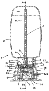
Figs. 1 and 2 show a first embodiment of a dispensing device
according to the invention. The dispensing device is denoted overall
by reference numeral 1. The dispensing device 1 is of the squeeze
foamer type. Such a squeeze foamer generally dispenses a foam
through a dispensing opening as a result of a container being
squeezed. After it has been squeezed, the container will return to
the original state, either by the elasticity of the container itself
or by restoring means which are provided in order to return the
container to its original state.
The foam which can be formed using the dispensing device 1 may be
suitable for various different uses, such as, for example, as soap,
shampoo, shaving foam, washing-up liquid, sun-tan lotion, after-sun
lotion, washing liquid, skincare products and the like.
The dispensing device is shown in the rest position, that is to say
that the container is not being squeezed. Such a squeeze foamer can
be operated by hand. However, it is also possible to push the
container in using a device intended for the purpose.
The illustrated squeeze foamer can be held in a hand during
delivery. It is also possible to install it or a similar dispensing
device into a holder which is to be attached, for example, to the
wall, similar to holder which can, for example, be found in public
toilets.
The dispensing device 1 comprises a manually compressible container
2 containing a liquid and air. The container has an opening 3 in
which a foam-forming assembly is fitted. The container 2 may have
any suitable shape, for example a shape having an elliptical or a
CA 02640063 2008-07-23
WO 2007/086730
PCT/NL2007/000022
6
circular cross section.
The foam-forming assembly is substantially circular-symmetrical
around a center axis of symmetry A-A. The foam-forming assembly
comprises a housing with a first housing part 4 and a second housing
part 5. The second housing part 5 is attached to the container 2 by
means of a threaded connection, the first housing part 4 being
clamped in a sealing manner between the container 2 and the second
housing part 5. Alternatively, the second housing part 5 may be
attached by means of a snap connection, a welded connection, an
airtight seal or another suitable connection on or in the container
2. Furthermore, the foam-forming assembly comprises a substantially
conical valve body 6 which is clamped near clamping section 6a
between the first housing part 4 and the second housing part 5. The
valve body 6 is made from a flexible, preferably elastic material.
Silicone has proved to be a particularly suitable material for the
valve body 6.
Relative to the liquid, the air is situated at the top of the
container 2. This liquid and this air can be turned into a foam by
means of the dispensing device 1, which is dispensed through a
dispensing opening 8 in the sealing cap 7. In order to make mixing
of the liquid and the air possible, a liquid passage is provided
which runs from the liquid in the container via an opening 9 in the
first housing part 4 to an annular mouth 10 (between the circular
edges 4a and 4b) of the liquid passage.
For the air, an air passage is provided which runs from the air at
the top of the container 2 via the tube 11 to an annular mouth 12
(between the circular edges 4a and 4c) of the air passage. In the
rest position shown, both the annular mouth 10 and the annular mouth
12 are sealed by the valve body 6. When the two annular mouths 10,
12 are opened, that is to say not sealed by the valve body 6, the
liquid passage and air passage are in communication with a
dispensing passage. The dispensing passage runs through the central
part of the valve body 6, in which a sieve element 13 with two small
sieves 13a is arranged, through a central opening 14 of the valve
body 6, through the second housing part 5 and the sealing cap 7 to
the dispensing opening 8.
CA 02640063 2013-08-27
7
As a rule, the air passage contains one or more air ducts which
bring the air in the container in fluid communication with a mouth
of the air passage which, in the rest position, is covered by the
valve body. The liquid passage correspondingly contains one or more
liquid ducts which bring the liquid in the container in fluid
communication with the mouth of the liquid passage which, in the
rest position, is covered by the valve body.
The annular mouth 10 of the liquid passage, the annular mouth 12 of
the air passage and the dispensing passage are arranged
substantially concentrically with respect to one another. The
diameter of the annular mouth 10 is in this case larger than the
annular mouth 12. Furthermore, the inner diameter of the central
opening 14 in the valve body 6 is smaller than the diameter of each
of the annular mouths 10 and 12. Now, the valve body 6 will be
discussed in more detail. At the clamping section 6a, the valve body
6 is sealingly clamped between the first housing part 4 and the
second housing part 5. Furthermore, the valve body is retained by
the circular edges 4a and 4c against the conical surface 5a. In
order, in the rest position, to achieve a better sealing along the
circular edges 4a and 4c, the valve body 6 is fitted with some axial
pretension between the first housing part 4 and the second housing
part 5.
23
The valve body 6 has an arcuate section 6c which is located, at
least partly, in the annular mouth 10 of the liquid passage. This
arcuate section 6c has the advantage that, as a result of the liquid
column in the container and the liquid passage which, in the rest
position, presses on the valve body, an improved sealing is obtained
at circular edge 4a. This is due to the fact that the arcuate
section 6c is pushed in, as a result of which the sides of the arch
are pushed sideways. As a result, the outside of the arcuate section
6c is pushed towards the clamp section 6a, and the inside of the
arcuate section 6c is pushed against the circular edge 4a as well as
against the circular edge 4c, which increases the sealing action.
In this case, it is particularly advantageous that the cross section
of the arcuate section 6c which extends inside the annular mouth 10
CA 02640063 2013-08-27
8
is not of a symmetrical design, but that a top of the arcuate
section 6c is situated relatively close to the edge 4a, i.e. that
the top of the arcuate section 6c is closer to the edge 4a than to
the edge 4b. As a result of this shape, the arcuate section 6c will,
under the pressure of the liquid column, in particular press against
the edge 4c, resulting in a good sealing here. As the annular mouth
is sealed on the other side by the clamp at section 6a, the mouth
is efficiently sealed off by the valve body 6 without a great
clamping force being required.
In an alternative embodiment in which the valve body 6 is not
clamped to one of the sides of the mouth, a top can be provided near
both edges of the mouth in order to achieve the advantageous very
strong clamping effect of the arcuate section of the valve body on
both edges. The cross section of the arcuate section of the valve
body then resembles the back of a camel, the two tops of the valve
body representing the humps of the camel.
On the side situated on the outside of the clamping section 6a, the
valve body 6 has a sealing lip 6b which serves as a valve for an air
inlet valve which allows air into the container 2 when a certain
reduced pressure is created in the container 2 as a result of the
liquid in the container 2 being dispensed. The sealing lip 6b
normally seals the passage of the container 2 towards the outside,
but will allow a flow of air from outside into the container 2
through the opening 15 when there is a reduced pressure in the
container 2.
The dispensing device 1 furthermore comprises a sealing cap 7.
Relative to the second housing part 5, this sealing cap 7 can be
moved at least into an open position, as shown in Figs. 1 and 2, and
a closed position (towards the top in the drawing, relative to the
housing). In the closed position, a projecting section 5b of the
second housing part 5 is moved into the dispensing opening 8 so that
no foam can be dispensed through the dispensing opening 8. The air
inlet passage which, via the sealing lip 6b and the opening 15,
leads to the interior of the container 2, is sealed when the sealing
cap is placed in the closed position. The sealing cap 7 still has a
number of upwardly pointing fingers which engage with complementary
CA 02640063 2013-08-27
. .
9
fingers on the second housing part 5. These intermating fingers form
further sealings in the closed position.
Near its outer periphery, the first housing part 4 has a free
projecting lip 29 which extends obliquely in the direction of the
container 2 and inwards (towards the centre line A-A). This lip 29
serves as a sealing element for sealing the connection between the
first housing part 4 and the container 2. Such a sealing is also
known as a crab claw, but has not yet been used in a foam-dispensing
device, in particular not in a squeeze foamer.
When the container 2 is squeezed in the open position of the sealing
cap, the pressure in the container 2 will increase. Initially, the
increasing pressure will ensure that the arcuate section 6c of the
valve body 6 is pressed more strongly against the edge 4a, resulting
in an improved sealing between the valve body 6 and the edge 4a.
When the pressure in the container 2 is increased further by
squeezing the latter, the arcuate section 6c will at some point move
down, as a result of which it will detach from the edge 4a. This
will lead to a stream of liquid flowing through the gap between the
edge 4a and the valve body 6. As a result of the increasing pressure
in the container 2, the valve body 6 will subsequently also become
detached from the edge 4c, making it possible for air and the stream
of liquid to flow between the edge 4c and the valve body 6. Here,
the liquid will thus be mixed with the air. Since both the liquid
and the air will flow through a narrow circular gap, a good mixture
between the air and the liquid will result. This mixture of air and
liquid will then flow through the small sieves 13a, which will
produce an (improved) foam. This foam will flow down through the
dispensing passage towards the dispensing opening, where it will be
dispensed.
The valve body 6 thus as it were successively rolls over the edges
4a and 4c during dispensing as a result of which the liquid and air
can flow via the dispensing passage to the dispensing opening,
creating a foam in the dispensing passage. It has been found that
this rolling effect is advantageous for forming a foam.
A first advantage of the embodiment of the dispensing device 1 is
CA 02640063 2008-07-23
WO 2007/086730
PCT/NL2007/000022
that the annular mouths of the liquid passage and the air passage
distribute the liquid and the air over a relatively large surface
area, resulting in a relatively good mixing. Incidentally, this
advantage is also achieved when one or both of the annular mouths
5 extend over less than 360 degrees or are subdivided into several
openings which together form an interrupted annular opening. Such
embodiments are considered to fall within the scope of protection of
the invention.
10 In an alternative embodiment, it is possible to design the valve
body to be stiff and to press or pull it against the first housing
part 4 using a spring element. When the pressure in the container is
increased, the spring will then be compressed or extended,
respectively, creating a gap between the valve body 6 and the second
housing part 4. As a result, it will be possible to form and to
dispense a foam. However, in such an embodiment the advantageous
rolling effect described above will not occur.
A second advantage of the embodiment of the dispensing device 1 is
that as a result of the central opening 14 which is provided in the
valve body, the stream of liquid and/or the stream of air does not
have to turn corners of 90 degrees or more. By providing this
opening 14, the stream of liquid and the stream of air can maintain
their speed, thus resulting in a better mixture of the liquid and
the air. In this case, it is furthermore advantageous that the valve
body 6 is designed to be substantially conical as a result of which
the speed of the stream of liquid and the stream of air is
maintained even more effectively. In addition, the conical shape has
the advantage that a sieve element assisting the production of foam
can be fitted in the cone. By fitting it in the conical shape, the
total height of the housing is reduced, Generally, the illustrated
embodiment of the dispensing device has the advantage that the
liquid to be dispensed moves in a direction relative to the
direction of the center axis of symmetry while it is being
dispensed. This is made possible by the specific construction of the
dispensing device and aids the production of a foam of the desired
quality.
A third advantage of the embodiment of the dispensing device 1 is
CA 02640063 2013-08-27
11
that the arcuate section 6c of the valve body 6 supports the sealing
between the first housing part 4 and the valve body 6. As a result,
a better sealing is achieved in the rest position, i.e. when the
container 2 is not being squeezed, thus reducing the risk of liquid
leaking from the dispensing device. In addition, the arcuate section
6c creates a pressure threshold value, at which the valve body
becomes detached from the first housing part 4, ensuring an improved
foam of constant quality.
Fig. 3 (i.e. Figs. 3a and 3b) shows a second embodiment of a squeeze
foamer according to the invention. This squeeze foamer is generally
constructed in accordance with the embodiment shown in Figs. 1 and
2. Therefore, identical reference numerals have been used to denote
substantially identical components of this squeeze foamer.
Furthermore, the above-described operation of the squeeze foamer
according to Figs. 1 and 2 generally also applies to the embodiment
from Fig. 3.
The most important difference between the squeeze foamer from Figs.
1 and 2 and the squeeze foamer from Fig. 3 is that the latter
comprises a third housing part which is denoted in Fig. 3 by the
reference numeral 20. As a result of this additional housing part
20, the squeeze foamer from Fig. 3 has a number of added advantages,
as will be described below.
The third housing part 20 is clamped between the clamping section 6a
on the valve body 6 and the first housing part 4. In this
embodiment, the valve body 6 is thus clamped between the second
housing part 5 and the third housing part 20. The first housing part
4 comprises sleeves 4e/4f, in which the openings 9a and 9b,
respectively, are provided. These sleeves 4e/4f are placed in an
opening 24 of the third housing part in a sealing manner.
The liquid which flows through the opening 9a to the annular mouth
10 is thus not able to reach a space 21 which is situated between
the first housing part 4 and the third housing part 20. This space
21 connects the space 22 just above the sealing lip 6b to the
interior of the tube 11. As a result, the air which enters through
the sealing lip 6b during aeration of the container 2 following
CA 02640063 2013-08-27
12
the dispensing of a certain amount of liquid, will successively flow
through the spaces 22 and 21 and through the tube 11 into the top
section of the container 2. Compared to the embodiment of Figs. 1
and 2, the air is prevented from passing through the liquid in the
container 2 prior to the aeration of the container 2. The latter has
the disadvantage that a foam may already be formed in the container
2 as the air required for aerating the bottle flows through the
liquid.
By forming a space 21 using a third housing part 20, the production
of foam in the container 2 during aeration is thus prevented in a
constructionally simple manner. In an alternative embodiment, it is
possible, for example in the embodiment from Figs. 1 and 2, to
provide an air duct through the first housing part 4 or the second
housing part 5, which air duct connects the air inlet valve with the
interior of the riser, so that the container can be aerated without
air having to flow through the liquid in the container.
Another advantage of the embodiment of the squeeze foamer from Fig.
3 is the fact that, by providing the third housing part 20, it is
possible, in a simple manner, to make the squeeze foamer capable of
supplying a foam with two or more air/liquid ratios, as will be
explained in more detail below.
Fig. 4 shows a top view of the first housing part 4. This first
housing part 4 is substantially circular and comprises a central
opening 23 surrounded by six openings, three openings 9a having a
larger diameter than the other three openings 9b. While foam is
being dispensed and also during aeration of the container 2, air
will flow through the central opening 23. Depending on the desired
air/liquid ratio, one or more of the openings 9a and 9b are provided
in order to allow liquid to flow through them while the squeeze
foamer is being operated.
Fig. 5 shows a top view of the third housing part 20. This third
housing part 20 comprises three openings 24 which can be brought in
line with either the large openings 9a or the small openings 9b of
the first housing part 4, depending on the position of rotation in
which the third housing part 20 is placed on the first housing part
CA 02640063 2013-08-27
13
4. The third housing part 20 furthermore comprises three blind holes
25 which, depending on the position of the first housing part 4
relative to the third housing part 20, will either seal the large
openings 9a or the small openings 9b.
Fig. 3 clearly shows, on the left-hand side, that the sleeve 4e of
the first housing part 4, in which the opening 9a is provided, is
positioned in the sleeve, in which the opening 24 is provided, while
the sleeve 4f, shown on the right-hand side in the figure, in which
the opening 9b is provided, is sealed by the blind hole 25. During
operation of the squeeze foamer 1, the liquid will therefore only
flow through the three large openings 9a.
If the first housing part 4 and the third housing part 20 were now
to be rotated 60 degrees with respect to one another, the openings
24 would be lined up with the small openings 9b, while the large
openings 9a would be sealed by the blind holes 25. This would result
in less liquid flowing from the openings 9b during operation of the
squeeze foamer, whereas the amount of air which flows through the
tube 11 as a result of the container 2 being squeezed would remain
virtually the same. Thus, the air/liquid ratio will change depending
on the position of rotation of the first housing part 4 relative to
the third housing part 20.
It will be clear to the person skilled in the art that this
construction offers many possibilities for changing the air/liquid
ratio by varying the number of openings in the first housing part
which are optionally sealed by a blind hole as well as by varying
the size of the respective openings.
A further possibility to influence the air/liquid ratio is through
the adjustment of the smallest diameter of the air passage, for
example by adjusting the inner diameter of the tube 11 or by
adjusting the diameter of the central opening 23 in the first
housing part 4. The options which have been given for adjusting the
air/liquid ratio can also be used to affect the total amount of foam
which is formed when the container 2 is squeezed.
In the present embodiment of Fig. 3, only two positions are
CA 02640063 2013-08-27
,
14
possible: one as shown in Fig. 3, where the liquid is dispensed
through the three large openings 9a, and a position in which the
first housing part 4 is rotated by 60 degrees relative to the third
housing part 20 and in which the liquid is thus dispensed through
the three small openings 9b. When fitting the various components of
the squeeze foamer 1 onto the container 2, a choice will be made
regarding the position in which the first housing part 4 would be
fitted with respect to the third housing part 20, for example
depending on the liquid.
Fig. 5 furthermore shows that the central section and the outer
section of the third housing part 20 are connected to one another by
bridge parts 26. These bridge parts 26 result in the mouth 12 being
formed by three openings, which openings are arranged in a ring
shape. Such an embodiment of the mouth 12 with several openings is
deemed to be a substantially annular mouth as referred to in the
context of the present patent application.
A further difference between the embodiment from Fig. 3 and the
embodiment from Figs. 1 and 2 is that, in the embodiment from Fig.
3, a second sieve element 28 comprising two small sieves 28a is
provided. Depending on the foam to be formed and the liquid which is
used for this purpose, this second sieve element 28 may be used to
further affect the quality of the foam to be dispensed. In general,
the provision of additional sieve elements will result in the foam
becoming more refined and also more homogeneous. Depending on the
application, it is thus possible to choose one of the sieve elements
13, 28 or the combination thereof, it also being possible to modify
the type of small sieve which is used in the respective sieve
elements 13, 28 to suit the application. In an alternative
embodiment, the sieve elements 13, 28 can also be designed as a
single sieve element, half of this single sieve element extending
into the valve body.
In the embodiment of Figures 3a and 3b, one of the small sieves 13a
is replaced by a small plate having one or more relatively small
holes, giving the sieve element also the function of an expansion
space.
CA 02640063 2013-08-27
. .
In the dispensing passage a constriction element is formed which
constricts the cross section surface area of the dispensing opening
at the constriction. The constriction causes an acceleration of the
foam flow or liquid-air mixture flow in the dispensing passage
5 therewith improving the quality of the foam. The constriction
element is designed integrally with the sieve element 13. In another
embodiment the constriction element can be provided by a separate
element or an element integrated in another part of the foam-forming
assembly.
The cross section surface area of the constriction element is
preferably maximally 75%, more preferably maximally 50%, of the
cross section surface area of the dispensing passage upstream of the
constriction.
The constriction is arranged upstream of at least one of the sieves
28a, or generally before the last porous element or sieve element.
By arranging the constriction upstream of at least one of the
sieves, the forming of foam is further positively influenced.
The above-described embodiments of a squeeze foamer have been
described in a position where the cap points downwards. All
references to above and/or below are made relative to this position.
The dispensing device is designed to be used in this position. In
this case, the sealing cap 7 is designed such that the dispensing
device can stand on this sealing cap 7, whereas the container 2, due
to its convex top, is not suitable to stand on this top. However, it
is possible to provide an embodiment in which the dispensing device
can indeed be turned upside down (inverted with respect to the
position shown) in order to dispense foam and/or rest. Such
embodiments are deemed to fall within the scope of protection of
this invention.
It will be clear to the person skilled in the art that all
individual features which have been mentioned with respect to one of
the aspects can also be applied in an embodiment according to one of
the other aspects of the invention. Such embodiments are thus deemed
to fall within the scope of protection of the invention.